Bosch Security Systems, Inc.
130 Perinton Parkway
Fairport, NY 14450
USA
www.boschsecurity.com
Bosch Sicherheitssysteme GmbH
Robert-Bosch-Ring 5
85630 Grasbrunn
Germany
© 2018 Bosch Security Systems, Inc. F.01U.265.450 | 07 | 2018.05
Copyright
This document is the intellectual property of Bosch Security
Systems, Inc. and is protected by copyright. All rights reserved.
Trademarks
All hardware and software product names used in this
document are likely to be registered trademarks and must be
treated accordingly.
Bosch Security Systems, Inc. product manufacturing dates
Use the serial number located on the product label and refer to
the Bosch Security Systems, Inc. website at
http://www.boschsecurity.com/datecodes/.
El-gr: Μεταβείτε στη διεύθυνση https://gr.boschsecurity.com/el/ για την
τεκμηρίωση σε αυτήν τη γλώσσα.
Es-es: Visite https://es.boschsecurity.com/es/ para obtener documentación en
este idioma.
Fr-fr: Accédez à l’adresse https://fr.boschsecurity.com/fr/ pour obtenir la
documentation dans cette langue.
Hu-hu: A honosított dokumentációt lásd a https://hu.boschsecurity.com/hu/
oldalon.
It-it: Andare a https://it.boschsecurity.com/it/ per la documentazione in questa
lingua.
Pl-pl: Dokumentacja w tym języku znajduje się w witrynie https://
pl.boschsecurity.com/pl/
Pt-br: Acesse http://pt.boschsecurity.com/pt/ para obter a documentação neste
idioma.
11 | Specifications
Dimensions 6.2 in x 4.7 in x 1 in (158 mm x
120 mm x 26 mm)
Voltage (input) 12 VDC nominal
Current 35 mA in standby mode
70 mA in alarm mode
Operating temperature 0°C to +50°C (+32°F to +122°F)
Relative humidity 5% to 93% at +32°C (+90°F)
non-condensing
Terminal wire size 12 AWG to 22 AWG (2 mm to 65
mm)
SDI2 wiring Maximum distance - wire size
(unshielded wire only):
1000 ft (305 m) - 22 AWG (0.65
mm)
Compatibility B9512G/B9512G-E
B8512G/B8512G-E
B6512/B5512/B4512/B3512
D9412GV4 version 2.0 and
higher
D7412GV4 version 2.0 and
higher
(Refer to the control panel
installation document for
number of supported devices.)
Region Certification
US UL 365 - Police Station Connected Burglar Alarm
Units and Systems
UL 609 - Local Burglar Alarm Units and Systems
UL 985 - Household Fire Warning System Units
UL 1023 - Household Burglar-Alarm System Units
UL 1076 - Proprietary Burglar Alarm Units and
Systems
UL 1610 - Central Station Burglar Alarm Units
CSFM - California Office of The State Fire Marshal
FCC Part 15 Class B
CA Canada CAN/ULC S303 - Local Burglar Alarm
Units and Systems
CAN/ULC S304 - Signal Receiving Centre and
Premise Alarm Control Units
CAN/ULC S559 - Fire Signal Receiving Centres
and Systems
ULC-ORD C1023 - Household Burglar Alarm
System Units
ULC-ORD C1076 - Proprietary Burglar Alarm
Units and Systems
ICES-003 - Digital Apparatus
9 | Keypad cleaning
Use a soft cloth or a non-abrasive cleaning solution. Spray the cleaner
onto the cloth, not the keypad.
10 | Certifications
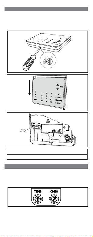
1. To remove power to the keypad, remove it from the base.
2. Return the keypad to the base to restore power.
The keypad shows the
model number, keypad address, and
firmware version for 10 seconds.
8 | Showing the firmware version
NOTICE!
You can also view a keypad’s firmware version in RPS.
The control panel supervises all SDI2 devices. Any device
that fails to respond will be declared missing.
7 | Supervision
6 | Audible tones
The keypad has a built-in speaker that produces several distinct
warning tones.
Tone Description
Fire alarm Emits a pulsed, high-pitched bell tone.
Gas alarm Emits a unique high pitched tone.
User alarm The tone sounds for the programmed
amount of time.
Burglary alarm Emits a steady, high pitched bell tone.
Entry delay Emits an intermittent beep tone during entry
delay periods.
Exit delay Emits an intermittent beep tone during exit
delay.
Invalid button
buzz
Emits a flat buzz tone.
Keypress Emits a muted beep tone.
Trouble Emits a two-tone warble until you enter a pro-
grammed passcode.
Watch point
fault
Emits a single clean tweedle tone.
5 | Status indicators
Status
indicator
Function
Ready to turn on (arm)
Turned on (armed)
System trouble
GAS Gas alarm
AC power present
en Installation Guide
Two-line Alphanumeric Keypad
B920