CIT Superior VAS-4 User manual

VAS-4
VACUUM MONITORING
SYSTEM
INSTALLATION
AND USER’S GUIDE
VAS-4 O&M Manual, Revision 0, 01 July 2020
Chemical Injection Technologies, Inc.
835 Edwards Road, Fort Pierce, FL 34982
Tel: 772-461-0666 Fax: 772-460-1847
Bulletin 4018
Pub. No. 0720-1 Copyright © 2020, Chemical Injection Technologies,Inc. Printed in U.S.A.

Table of Contents
Section 1 Introduction ................................................................. 1
Section 2 Inventory ...................................................................... 1
Section 3 Specifications .............................................................. 2
Section 4 Operation Basics ......................................................... 3
Digital Display .............................................................. 3
LED Indicators ............................................................. 3
Alarm Outputs ............................................................. 4
Section 5 Installation ................................................................... 4
Opening Unit ................................................................ 5
Enclosure Mounting .................................................... 5
Installing Vacuum Hose .............................................. 6
Installing Power/Alarms .............................................. 6
Section 6 Set Up and Calibration ................................................ 6
Delay Timer Adjustment ............................................. 6
Low Level Adjustment ................................................ 7
High Level Adjustment ............................................... 7
Alternate Method for Adjustment .............................. 7
Analog Output ............................................................. 8
Maintenance and Calibration ..................................... 8
Warranty Information .................................................. 9
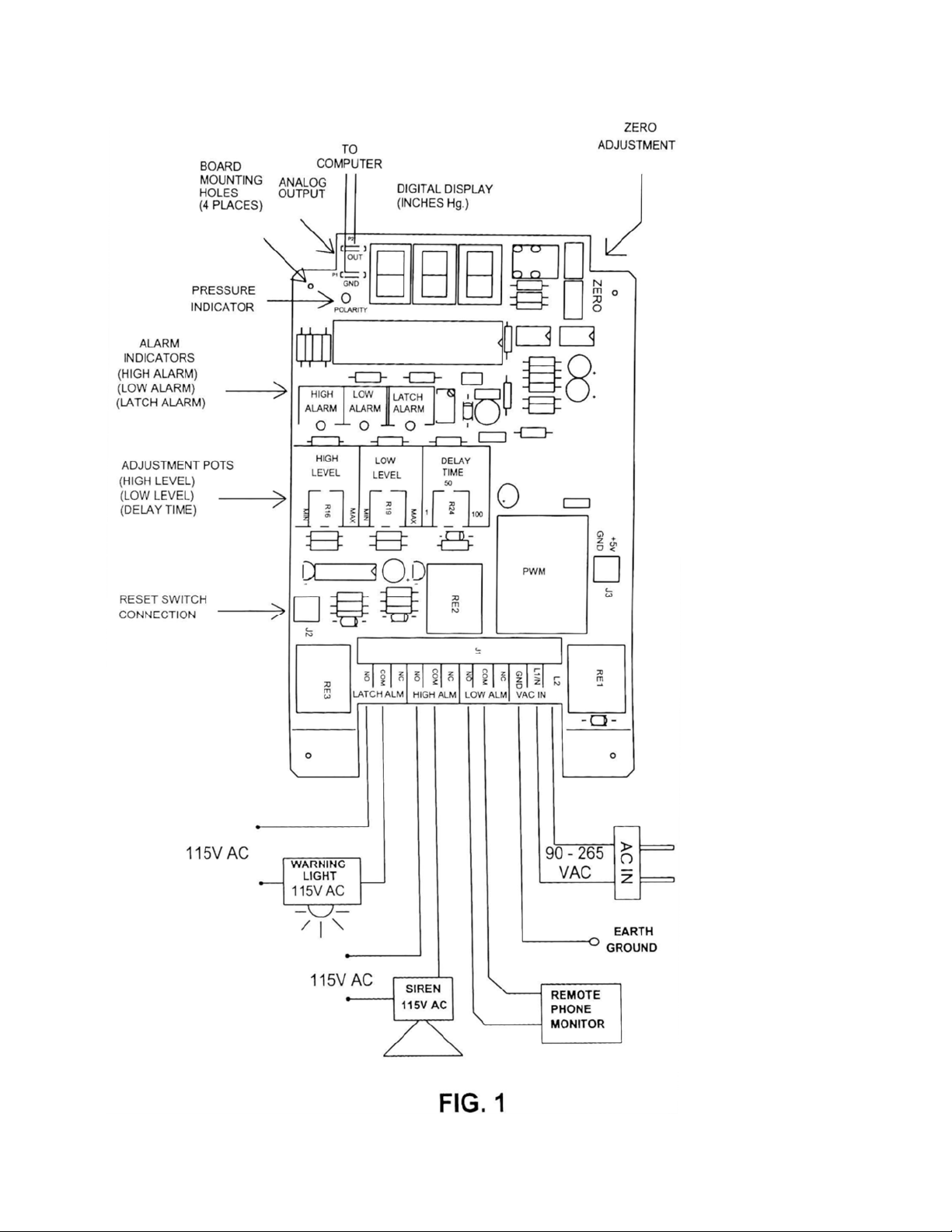
Figure 1 Installation Diagram .................................................. 10
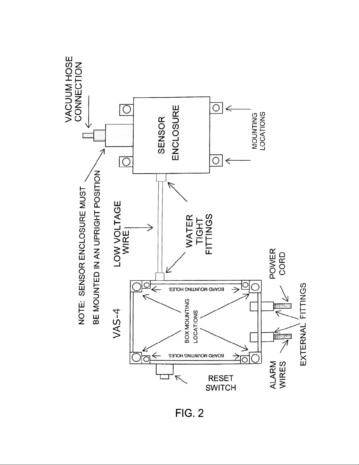
Figure 2 Enclosure Mounting .................................................. 11
VAS-4 O&M Manual, Revision 0, 01 July 2020

1
Section 1 Introduction
The VAS - 4 is a full-featured vacuum monitoring system. The system uses
the latest in integrated circuit technology, which allows a compact design,
accuracy and reliability. The VAS - 4 features both high and low vacuum
detection, separate high, low and latch alarm relays, three digit display of
vacuum in inches of Hg., LED status indicators and an analog output. The
high and low alarm levels are user adjustable along with a variable delay
timer. The enclosure has a NEMA 4X rating; therefore it can be mounted
outside. Applications include loss of chlorinating in water and wastewater
treatment, pool pump monitoring, automotive test equipment and many
others.
Section 2 Inventory
The following items are included with the VAS - 4:
1.
VAS - 4. Contains the electronics housed in a NEMA 4X enclosure.
2.
Sensor enclosure with oil based protection device.
3.
Two watertight fittings used for running the power and alarm
wires from the control box to the alarms.
4.
¼” tube fitting attached to the oil based protection device.
5.
Power cord.
6.
Instruction manual.
7.
Warning label attached to the oil based protection device.

2
Section 3 Specifications
Input Voltage: 90-265 VAC 50/60 Hz
Alarm Relays: NO\NC Type
240V AC @ 5A Resistive Load
115V AC @ 5A General Use
30V DC @ 5A General Use
Gas\Fluid compatibility: System includes a protection device that uses a
chemically inert synthetic oil compatible with chlorine, sulfur dioxide, and
ammonia gas.
Enclosure: .............................................................................NEMA 4X Rated
Vacuum Measurement Range: ................................................ 0 to 30 inHg
Low Alarm Range: ................................................................... 0 to 15 inHg
High Alarm Range: ................................................................ 15 to 30 inHg
Over Pressure: ................................................................................... 50 PSI.
Delay Timer: .............................................................................. 1 to 100 sec.
Analog output:
Voltage: ............................................................................. 0 to 3 VDC.
Current: ......................................................................... 0 to 3 ma DC.
Reset Switch:........................................................................ IP 65 protection
External Connectors: ............................................................ IP 68 protection
Indicators:
Vacuum: ....................................................... 3-Digit Digital LED Display
Alarms: ..................................... 3 LED Indicators/High, Low and Latch
Polarity: .................................................... 1 LED indicator for pressure
Temperature Range (System):
Storage: . . . . . . . . . . . . . . . . . . . . . . . . . . . . . . . . . . . . . -30 C to 70 C
Operating: . . . . . . . . . . . . . . . . . . . . . . . . . . . . . . . . . . . -20 C to 50 C
Vacuum Temperature Range: . . . . . . . . . . . . . . . . . . . . . -40 C to 50C
Humidity ................................................... Relative 0 to 90% Noncondensing
(Specifications are subject to change without notice.)

3
Section 4 Operation Basics
Digital Display
The three-digit display represents the real time vacuum pressure in inches of
mercury (inHg). Minimum vacuum equals 00.0 and the maximum vacuum
reading, depending on altitude, is approximately 30.9 inHg.
LED Indicators
The VAS - 4 has four LED indicators; High, Low, Latch and Polarity. See
Fig. 1 for their locations.
High LED Indicator
This LED indicates that the vacuum pressure exceeds the preset High Alarm
set point.
NOTE: This indicator is real time, i.e., it does not wait for the delay timer to
time out.
Low LED Indicator
This LED indicates that the vacuum pressure is below the preset Low Alarm
set point. This LED indicator is also real time.
Latch LED Indicator
When either the high or low indicators are active, this starts the delay timer.
If the alarm is active longer than the preset delay time, then the latch LED
indicator will become active. This indicator stays active until the manual reset
button (see Fig. 2) is pushed. This indicator implies that either an alarm has
occurred or is still active. If the latch indicator is on and the High/Low
indicators are off, then an alarm condition has occurred, but is not active now.
If either the High or Low indicators are active, then this represents that the
alarm condition is still active.
NOTE: The High or Low alarm relays do not become active until the latch
alarm indicator is on.
Polarity LED Indicator
When this LED is on this indicates that the VAS - 4 is measuring
pressure. The digital display shows this pressure measurement in inches
of mercury (inHg). (1 inHg = 0.49 psi)

4
Alarm Relays
The VAS - 4 has three alarm relay outputs. The alarm relays do not
become active until the delay timer times out, which causes the latch alarm
indicator to become active. The three alarm relays are general purpose
and can be used for exterior alarms, load switching or phone monitoring.
Note: Do not exceed relay specifications.
High Alarm Relay
The High Alarm relay becomes active from a high alarm condition after the
delay timer times out. This relay stays active as long as the alarm condition
exists. Once the alarm condition goes away, this relay becomes inactive.
Low Alarm Relay
The Low Alarm relay becomes active from a low alarm condition after the
delay timer times out. This relay stays active as long as the alarm condition
exists. Once the alarm condition goes away, this relay becomes inactive.
Latch Alarm Relay
When either the High or Low Alarm relays become active and the delay time
is over the latch alarm relay also becomes active. This is indicated by the
Latch Alarm indicator. This relay stays active until the manual reset button is
pushed (see Fig. 2).
NOTE: In some applications, like gas chlorination in water and wastewater
treatment, special attention needs to be given to the electrical hookup. If your
vacuum source under normal operation is cycled on and off, as is the case
when the vacuum is created only when a well pump is operating, then the
AC power to the VAS - 4 should be switched on and off with the well pump.
This will prevent a low alarm condition when the pump is off.
Section 5 Installation
Installation should only be performed by a licensed electrician. Follow any
local, state or other applicable codes that apply when installing this unit.
THIS UNIT SHOULD BE WIRED TO A GROUND FAULT RECEPTACLE.
CAUTION: HIGH VOLTAGE COULD EXIST INSIDE THIS UNIT.
DISCONNECT ALL POWER BEFORE INSTALLATION.

5
Opening Unit
Remove the four plastic screws to open the unit. The printed circuit board
contains static sensitive parts, so the installer should wear a grounding strap
when handling the board.
Enclosure Mounting
IMPORTANT: This unit contains two enclosures. The larger one contains the
electronics (VAS - 4) and the smaller one contains the sensor. The two
enclosures are permanently connected together by a low voltage wire. The
sensor enclosure contains an oil based protection device that is filled with a
special fluid. The protection device has a cap over the ¼" fitting to prevent the
oil from leaking out during shipping and installation. THE SENSOR
ENCLOSURE MUST BE MOUNTED IN AN UPRIGHT POSITION TO
PREVENT THE FLUID FROM LEAKING OUT. Once the unit is securely
mounted in an upright position, the cap over the ¼" fitting can be removed.
The recommended mounting method for the VAS - 4 is to use four mounting
holes located where the 4 plastic screws are that hold down the lid. Use the
box as a template for mounting (see Fig. 2).
NOTE: THE VAS - 4 SHOULD NOT BE MOUNTED WHERE SUNLIGHT
CAN DIRECTLY ENTER THE TRANSPARENT COVER.
The printed circuit board is designed to have power come ln from the bottom
of the box. Remove the knockouts that are needed for power entry. Two
watertight fittings are provided for the power and alarm line. If the board must
be removed to install a watertight fitting, care must be taken in handling the
board.
NOTE: IF YOU RUN CONDUIT INTO THE BOX AND DO NOT USE THE
WATERTIGHT FITTINGS, YOU MUST USE A SEALANT TO SEAL
AROUND THE CONDUIT CONNECTION.
Install the printed circuit board after the connectors have been installed. Use
the four #6 screws provided to mount the board in the box and tighten only to
a snug fit. DO NOT OVER TIGHTEN (see Fig. 2)

6
Vacuum Line and Reset Switch
Connect your ¼” vacuum hose to the ¼" barb fitting attached to the protection
device. The reset switch is prewired to the board reset terminals.
Power and Alarm Wiring
CAUTION: BE SURE POWER IS DISCONNECTED BEFORE HANDLING
ANY WIRES.
WARNING: IMPROPER WIRING TO THIS UNIT CAN DAMAGE UNIT AND
COULD CAUSE SERIOUS BODILY INJURIES. OVER PRESSURE ON THIS
UNIT IS RATED AT 50 PSI. EXCEEDING THIS PRESSURE CAN CAUSE A
RUPTURE OF THE SENSOR. See Fig. 1 for typical electrical wiring. Connect
input AC power to the connector location labeled L2, L1/N and GND.
NOTE: A surge arrestor is recommended on the AC power line to prevent
damage from lightning strikes or other power surges. The alarms can be
hooked up in many ways. Be sure the relay specifications are not exceeded.
The relay outputs are labeled HIGH ALARM, LOW ALARM and LATCH
ALARM. Remember the latch alarm will stay active until the reset button is
pushed.
Note: NO = Normally Open Contact
NC = Normally Closed Contact
COM = Relay Common
Section 6 Set up and Calibration
The VAS - 4 comes preset at the following default levels:
Delay: 50 sec.
Low Alarm: 5 in. Hg.
High Alarm: 25 in. Hg.
The following Is a procedure for changing these values. See Fig. 1 for the
location of the adjustment pots.
CAUTION: HIGH VOLTAGE EXISTS INSIDE THE UNIT.
Delay Adjustments
The delay time is adjustable from approximately 1 second to 100 seconds.
To adjust the delay, insert a small screwdriver into pot R24 rotate until the
desired delay is achieved. The delay value is printed on the board.

7
Low level Alarm
The Low Level alarm is adjustable from approximately 0.0 to 15 inches of Hg.
To adjust the low level, insert a screwdriver into pot R19 and rotate it to the
desired level. MIN = 0 and MAX = 15 inches of Hg.
NOTE: If you want to disable the low alarm, turn the pot counter clockwise
until it stops.
High Level Alarm
The High Level alarm is adjustable from approximately 15 to 30 inches of Hg.
To adjust the high level, insert a screwdriver into pot R16 and rotate it to the
desired level. MIN = 15 inches of Hg. and MAX = 30 inches of Hg.
NOTE: If you want to disable the high alarm, turn the pot clockwise until it
stops.
Alternate Method for Accurate
High/Low Level Adjustment
If a high degree of accuracy is required, then use the procedure in the
following example:
Example: If you desire a high level alarm at 26.3 inches of Hg.
1.
Adjust your vacuum level until the digital readout
reaches 26.3.
2.
Rotate the high level alarm pot full R16 counter-clockwise.
3.
Then, rotate the high level alarm pot R16 clockwise slowly until
the high level LED comes on. This represents
the correct adjustment for 26.3 inches of Hg.
This method can be used for low level adjustment, except the rotation of the
low level alarm pot R19 is reversed.

8
Analog Output
The VAS - 4 has an analog output, which will allow the vacuum to be
remotely monitored. The connection for this is located in the upper left
section of the printed circuit board (see Fig. 1). Two spade lugs are
provided for the connection. They are labeled GND for ground and OUT for
the output. The output is capable of sourcing 0 to 3 VDC or 0 to 3 ma. If a 4
to 20 ma loop is required, a signal conditioner can be used to convert the
output. These are available from many sources.
Maintenance and Calibration
Once the VAS - 4 has been in operation for approximately one week, the
unit should be checked for the correct zero reading. This is the reading
when no vacuum is present. Ideally, the zero reading would be 00.0.
However, due to the ambient temperature, some variation is normal. If the
zero reading is over 00.7 then an adjustment is needed. The zero
adjustment pots are located in the upper right hand comer of the board. One
of the pots, if looked at from, the middle of the board, is rotated all the way
to the right and the other pot is rotated to approximately the 12:00 position.
The pot that is close to the 12:00 position is the pot to adjust. Slowly turn
this pot to get the zero reading as close to 00.0 as you can. This will end
the zero calibration. If the reading still does not read 00.0 then slowly adjust
the other pot until a reading of 00.0 is set.
NOTE: AT LEAST ONE OF THE POTS MUST ALWAYS BE ROTATED ALL
THE WAY TO THE RIGHT.
Once a month the system should be functionally tested. This testing should
include all relays, LED indicators, delay timer and vacuum level accuracy. To
perform this test adjust your vacuum level up and down to cause the high and
low alarms to engage. The delay timer and reset can also be tested in the
same manner. At this time, inspect the board for any corrosion or loose wires.
If corrosion is present check all fittings for a snug fit.
DO NOT ATTEMPT TO CLEAN ANY CORROSION FROM THE BOARD.
HIGH VOLTAGE EXISTS ON THE BOARD.
Corrosion can only be removed by a trained technician. The outside of the
enclosure can be cleaned with warm water and a damp cloth.

9
LIMITED WARRANTY
THE MANUFACTURER. warrants this product to be free from defects in
material and workmanship for a period of one (1) year from the date of the first
consumer purchase.
Except as specified below, this warranty covers all defects in materials or
workmanship in this product. The following are NOT covered by the warranty:
1.
Any product on which the serial number has been defaced, modified or
removed.
2.
Damage, deterioration or malfunction resulting from:
a.
Accident, misuse, abuse, neglect, fire, water, lightning or any o t h e r
acts of Nature.
b.
Any unauthorized product modification or failure to follow
instructions supplied with the product.
c.
Repair or attempted repair by anyone not authorized by THE
MANUFACTURER.
d.
Any shipment of the product.
e.
Any other causes which do not relate to a product defect.
LIMITATION OF IMPLIED WARRANTIES
ALL IMPLIED WARRANTIES, INCLUDING WARRANTIES OF
MERCHANTABILITY AND FITNESS FOR A PARTICULAR PURPOSE, ARE
LIMITED IN DURATION TO THE LENGTH OF THIS WARRANTY.
EXCLUSION OF DAMAGES
THE MANUFACTURER’S LlABiLITY FOR ANY DEFECTIVE PRODUCT IS
LIMITED ONLY TO THE REPAIR OR REPLACEMENT OF THE PRODUCT
AT OUR OPTION. THE MANUFACTURER SHALL NOT BE LIABLE FOR:
1.
DAMAGE TO OTHER PROPERTY CAUSED BY ANY DEFECTS IN
THIS PRODUCT, DAMAGES BASED UPON INCONVENIENCE,
LOSS OF USE OF THE PRODUCT. LOSS OF TIME, OR
2.
ANY OTHER DAMAGES, WHETHER INCIDENTAL,
CONSEQUENTIAL OR OTHERWISE.
10
11

VAS-4
VACUUM MONITORING
SYSTEM
Chemical Injection Technologies, Inc.
835 Edwards Road, Fort Pierce, FL 34982
Tel: 772-461-0666 Fax: 772-460-1847
Table of contents


