Citadel TouchStar TS3000 User manual
TouchStar™
User Manual
TS3000/TS4000

TouchStar™
User Manual
TS3000/TS4000

2
TS3000/TS4000 TouchStar Systems User Manual
Citadel Computer Corporation has made every effort to ensure the accuracy and
completeness of the information contained in this User Manual. Citadel assumes
no liability arising out of the application or use of the information or products
described herein, or for technical or editorial errors or omissions. The informa-
tion contained in this document is subject to change without notice.
FCC Compliance
This equipment complies with the limits for a Class A digital device pursuant to
Part 15 of the FCC Rules. These limits are designed to provide reasonable
protection against harmful interference when the equipment is operated in a
commercial environment. This equipment generates, uses, and can radiate radio
frequency energy and, if not installed, operated, and maintained in accordance
with Citadel Computer Corporation guidelines, may cause harmful interference
to radio communications. Shielded cables must be used to ensure compliance
with the Class AFCC limits. Changes or modifications to this unit not expressly
approved by Citadel Computer Corporation could void the user’s authority to
operate the equipment, and could void the manufacturer’s warranty.
Limited Warranty
Citadel Computer Corporation warrants its TouchStar Information Systems to be
free from defects in material and workmanship under normal use and service for
a period of two years. Citadel Computer Corporation’s sole obligation under this
warranty shall be limited to repair or replace, at its option and at Citadel’s
facilities, all or any portion of any System which within two years after delivery
to the original purchaser, is returned and demonstrated to be defective. No
person, firm or corporation is authorized to assume any liability in connection
with the sale of this product on Citadel Computer Corporation’s behalf. Normal
use and service shall not include abuse, misuse, accident, alteration, neglect,
unauthorized repair or installation, operation or storage outside the environmen-
tal limits specified for this product, in-transit damage, improper maintenance, or
defects resulting from use with third party products not designed for use with
this product.
TouchStar is a trademark of Citadel Computer Corporation. All other trademarks
are the property of their respective owners.
© Copyright 1996-1997; Citadel Computer Corporation
Citadel Computer Corporation
29 Armory Road
Milford, NH 03058
(603) 672-5500
FAX: (603) 672-5590
Revision January 1997

3
TS3000/TS4000 TouchStar Systems User Manual
1 INTRODUCTION ........................................................................ 5
TouchStar Information Systems Overview ........................ 5
TS3000 ................................................................................. 5
TS4000 ................................................................................. 6
Front Panel ......................................................................... 6
Rear Panel ........................................................................... 6
Internal Configuration ..................................................... 7
CPU and Memory ........................................................ 7
System Software ........................................................... 8
Network Interface Card and Software ..................... 8
Accessories ......................................................................... 8
TS3000 ............................................................................ 8
TS4000 ............................................................................ 9
2 INSTALLATION AND MAINTENANCE ................................. 11
Physical Installation....................................................................11
TS3000 – Fixed Installation .................................................. 11
TS4000 – Mobile Installation ................................................ 11
TS4000 Physical Installation .......................................... 12
DC Power Converter Mounting/Installation ............. 12
Electrical Harness Access Cable.................................... 12
Network Connections ............................................................... 13
Hard-wired Network Connections .................................... 13
Token Ring........................................................................ 13
Ethernet............................................................................. 13
Wireless Network Connections .......................................... 13
Connecting External/Optional Equipment ........................... 14
DC Power Connection ......................................................... 14
Enhanced Parallel Port – LPT1 ........................................... 15
Serial Communication Ports ............................................... 16
Keyboard Port ....................................................................... 17
PCMCIA Slots........................................................................ 17
Antenna Connector .............................................................. 18
Maintenance................................................................................ 18
3 BASIC OPERATION ....................................................................19
Power-Up ................................................................................. 19
Booting-Up ................................................................................. 19
Reboot .......................................................................................... 20
Warm Boot ............................................................................. 20
Cold Boot ............................................................................... 20
Operating Modes and Environments ..................................... 21
Client-Server.......................................................................... 21
TABLE OF CONTENTS
TABLE OF CONTENTS

4
TS3000/TS4000 TouchStar Systems User Manual
Installing the DOS Operating System .......................... 21
Loading DOS Applications ............................................ 22
FLASH Disk ................................................................ 22
Floppy Disk................................................................. 22
Downloading from the Network............................. 22
Logging On to the Network .......................................... 22
Terminal Emulation .............................................................. 22
The Touchscreen Subsystem and Touch-based Operation .. 22
Touchscreen Components ................................................... 23
Touch Frame and Protective Bezel ............................... 23
Touch Controller Firmware and Driver Software ...... 23
Programming Touch-based Applications ......................... 23
General Functions and Guidelines ............................... 23
Main Application Program ............................................ 24
Touch Library ................................................................... 25
Graphics Library ............................................................. 25
APPENDIX A – Troubleshooting, Technical Support and
Equipment Returns ............................................................................27
Initial Checklist .......................................................................... 27
Specific Problems ....................................................................... 27
Technical Support ...................................................................... 30
Equipment Returns .................................................................... 30
APPENDIX B – System Reference ....................................................31
CPU .............................................................................................. 31
TouchStar BIOS ........................................................................... 31
System Memory Configuration ............................................... 32
CMOS RAM ................................................................................ 32
Flash Drives ................................................................................ 33
Real-Time Clock ......................................................................... 34
Battery Backup ........................................................................... 34
Interrupt Controller ................................................................... 34
DMA Controller ......................................................................... 35
Programmable Interval Timer .................................................. 36
Counter/Timer Circuit .............................................................. 36
PCMCIA Slots ............................................................................. 37
Audible Indicator ....................................................................... 38
APPENDIX C – Specifications ..........................................................39
TABLE OF CONTENTS

5
TS3000/TS4000 TouchStar Systems User Manual
INTRODUCTION ________________________ 1
TOUCHSTAR INFORMATION SYSTEMS OVERVIEW
Citadel’s TouchStar Information Systems are PC-compatible
computers ruggedized to withstand the physical shock, vibra-
tion and temperature extremes of harsh industrial or commer-
cial environments. All TouchStar systems provide a touchscreen,
full VGA display (either electroluminescent or LCD), multiple
network options and full I/O capability. Each TouchStar system
is fully PC-compatible with the MS-DOS, Versions 3.3 through
6.22, Windows 3.1 and Windows for Workgroups 3.11 operating
systems.
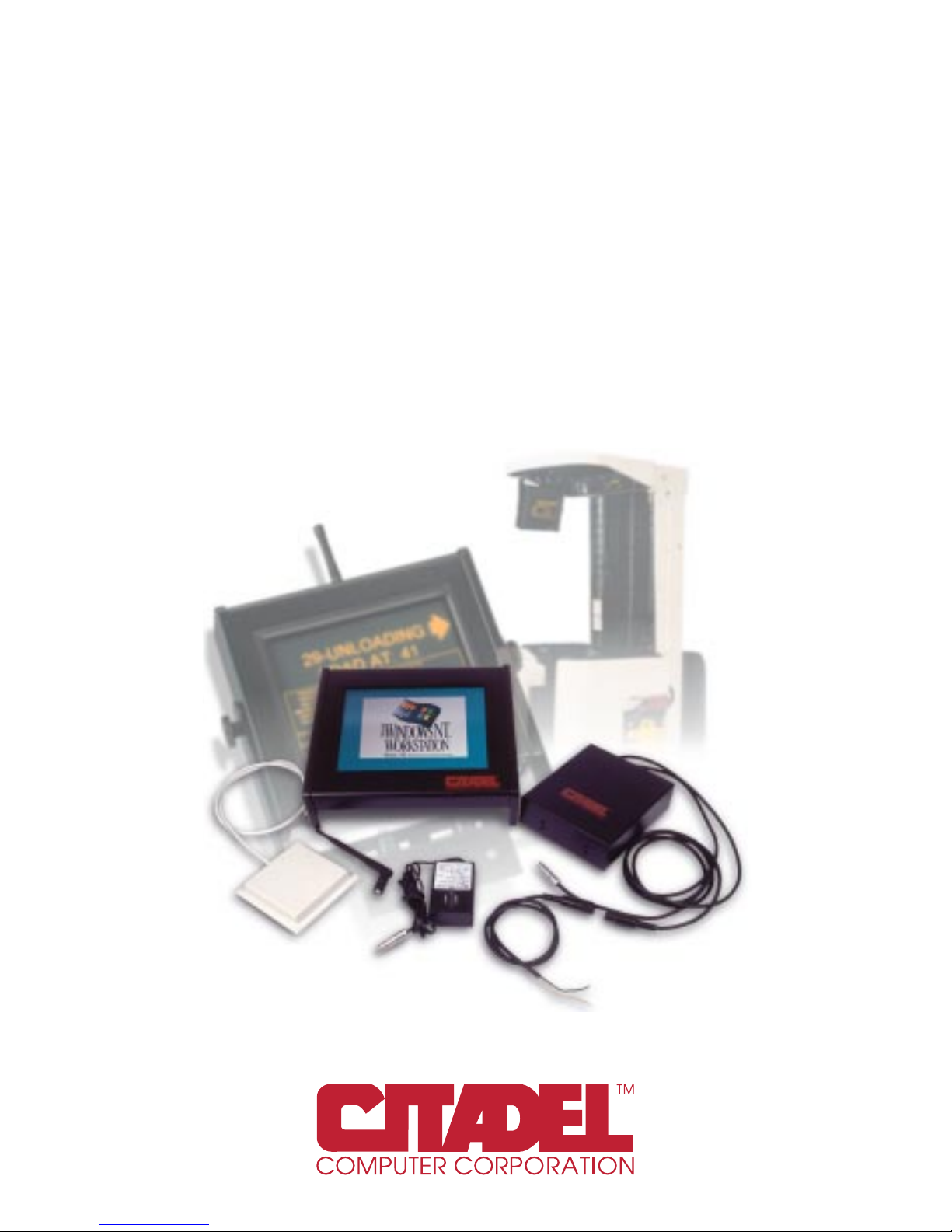
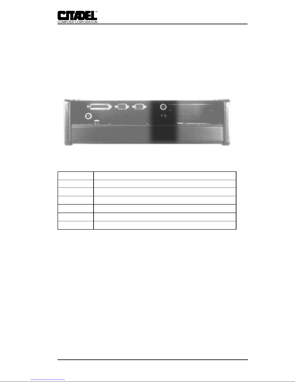
Figure 1. The TouchStar Information System
(Shown with two power supply options; Optional mounting brackets not shown)
TS3000
The TS3000 is designed for fixed-mount applications. It is
powered by a standard 110VAC outlet via a plug-in power
supply. It is hard-wired into the local area network (LAN).
Standard Ethernet or Token Ring hard-wired LAN connections
are supported. The TS3000 can also be equipped with wireless
(RF) network communications and used in fixed-mount applica-
tions where the installation of a hard-wired LAN is not practical
or cost-effective.

6
TS3000/TS4000 TouchStar Systems User Manual
TS4000
The TS4000 is designed for vehicular-mounted applications
such as on forklifts, hostlers and motorized pallets. It is pow-
ered from the vehicle’s electrical system (battery) through a
power converter. It uses a 2.4GHz spread-spectrum radio link to
communicate with (RF) network access points hard-wired into
the LAN. Antenna options include patch and “rubber duck”
types. Antenna connectors are non-standard to prevent antenna
substitution and resultant operation in violation of FCC regula-
tions.
Front Panel
The TouchStar front panel consists of a gasketed infrared
touchscreen mounted over a flat-panel video display. The
TouchStar is operated by touching the screen to activate func-
tions and initiate actions. Programming guidelines for touch-
screen-based applications are provided in separate manuals,
Touchscreen Driver for DOS and Touchscreen Driver for Windows.
The TouchStar is factory-configured with either an electrolumi-
nescent or active-matrix LCD flat-panel display system. All
touchscreen/display combinations operate in a similar manner.
The type of display provided in your particular TouchStar
model is matched to the specific requirements of your applica-
tion including ambient lighting, available viewing angle and
environmental extremes.
Rear Panel
All cabled connections to the TouchStar are made through the
rear panel, with the exception of the RF connection in wireless
communication-equipped systems. Located on the rear panel
are a RESET button, a power connector, a parallel I/O connec-
tor, two serial I/O connectors, and dual PCMCIA slots. Also
located on the rear panel are connectors for an external
keyboard, and network connections
1 - INTRODUCTION
7
TS3000/TS4000 TouchStar Systems User Manual
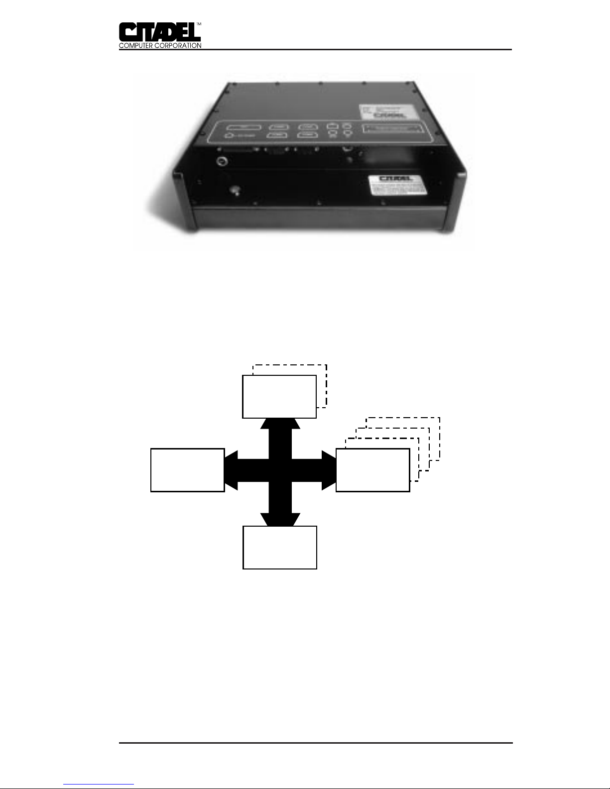
Figure 2. Rear Panel
Internal Configuration
Figure 3 depicts the block diagram of the TouchStar system.
Each of the blocks are described briefly below.
FLASH Memory (Disk Drive)
DRAM System MemoryCPU
BIOS and Setup
2MB
4MB
486SLC2-25/50
256K x 8
FLASH
4MB
8MB
12MB
16MB
Figure 3. TouchStar Block Diagram
• CPU and Memory
The TouchStar is shipped with a 486SLC2-25/50 central
processor unit (CPU). The system is configured with either
2MB or 4MB of non-volatile, solid-state FLASH memory to
emulate standard drive functions. System memory is
INTRODUCTION - 1

8
TS3000/TS4000 TouchStar Systems User Manual
supplied as 4MB, 8MB, 12MB or 16MB of dynamic RAM
(DRAM). The specific memory configuration is determined
at the time the system is ordered.
• System Software
A 256Kx8 flash device contains the System BIOS, the Video
BIOS, and a Setup Utility.
• Network Interface Card and Software
The TouchStar is factory-configured with a Local Area
Network Interface Card (NIC) which is installed in the
system expansion slot. The specific NIC is determined by
the type of network to be used, i.e. hard-wired or wireless.
Each NIC has a unique hardware address and interrupt and
DMA channel assignments, but no logical unit designation.
The NIC allows the TouchStar to be configured for a variety
of network environments.
The TouchStar is factory-configured with network protocol
layers that are specific to the operating system or NIC. For
the TouchStar to communicate with the network it requires
the installation of a network driver (IPX). Both ODI and
NDIS drivers support standard LAN operating systems.
Accessories
• TS3000
Hard-wired configurations of the TS3000 are supplied
with a wall-mounted 110VAC power supply, this manual,
and Touchscreen-based programming references. Wireless
configurations also include an antenna. The mounting
bracket for the TS3000 is optional.
1 - INTRODUCTION

9
TS3000/TS4000 TouchStar Systems User Manual
Figure 4. TS3000 System and Accessories (Mounting brackets not shown)
• TS4000
The TS4000 is supplied with the TouchStar computer itself, a
vehicle mounting bracket, DC power converter, vehicular
electrical system access cord, antenna, this manual, and
Touchscreen-based programming references.
Figure 5. TS4000 System and Accessories (Mounting brackets not shown)
INTRODUCTION - 1

10
TS3000/TS4000 TouchStar Systems User Manual

11
TS3000/TS4000 TouchStar Systems User Manual
INSTALLATION & MAINTENANCE _____________ 2
PHYSICAL INSTALLATION
TS3000 – Fixed Installation
The TS3000 TouchStar can be mounted almost anywhere that is
convenient to the operator. The mounting location must be near
a standard 110VAC electrical outlet, and there must be sufficient
space below the unit for cable access to the rear panel, which
faces downward when the unit is wall-mounted. The optional
mounting bracket should be secured to the wall prior to attach-
ing the TS3000 to the bracket.
All cable connections should be made to the TS3000 before the
system is powered up. Since there is no ON/OFF switch, the
unit will power up as soon as the power supply connections are
completed and the power supply is plugged in to the 110VAC
outlet.
Power line transients, spikes and sags induced by other equip-
ment in the operating environment can stress the TouchStar’s
power supply, and can reduce the voltage at the TouchStar
below its nominal +12VDC operating voltage. To avoid the
possibility of large inrush currents which will open the power
supply’s internal fuses, necessitating the premature replacement
of the power supply, the use of single-outlet surge suppresser/
spike protector is highly recommended.
TS4000 – Wireless, Mobile Installation
The TS4000 mounts to a forklift or other vehicle with a custom
bracket. Operating power is obtained from a DC power con-
verter that attaches to the vehicle’s electrical system via an
access cord. Installation of the TS4000 requires mounting the
custom bracket, installing the DC power converter, and attach-
ing the access cord to the vehicle’s electrical system. Since
vehicle electrical systems vary, the wiring instructions given
here are intended as a guide only. If you require specific instruc-
tions for a particular make and model forklift, hostler, or
motorized pallet, please contact Citadel’s factory.

12
TS3000/TS4000 TouchStar Systems User Manual
• TS4000 Physical Installation
The mounting bracket should be located so that the TS4000
touchscreen is clearly visible, easily accessible and easily
operated. Also, make sure that the intended mounting
location provides adequate access for cables to the rear
panel (bottom) of the TS4000. To provide maximum safety
for both the vehicle operator and the equipment, the TS4000
and its DC power converter should both be mounted
completely within the vehicle’s outer dimensions and
profile.
• DC Power Converter Installation
The DC power converter mounts to a steel surface on the
vehicle via its magnetic feet. It should be located so as not to
interfere with either moving parts on the vehicle or the
operator’s vision. Be certain that the TS4000 DC power
cable from the converter can reach the mating connector on
the TS4000.
• Electrical Harness Access Cable
The electrical harness access cable has WHITE and BLACK
leads at one end which are permanently wired into the
vehicle’s electrical system. The other end has a circular 3-pin
connector with rubber boot that mates with a similar
connector on the DC power converter’s power input cable.
The access cable should be connected either directly to the
vehicle’s battery or into the electrical system, at a filtered
power tap if possible, at a point that provides power at all
times. The BLACK harness wire is connected to the POSI-
TIVE battery terminal. The WHITE harness wire is con-
nected to the NEGATIVE battery terminal. The booted
connector end of the cable should be accessible for conve-
nient attachment to the DC power converter.
Make sure the DC power converter ON/OFF switch is in
the OFF position. Once the access cable is wired to the
electrical system, mate the connectors on the access cable
and the DC power converter power input cable. All cable
connections must be completed before applying power to
the TS4000.
2 - INSTALLATION & MAINTENANCE

13
TS3000/TS4000 TouchStar Systems User Manual
NETWORK CONNECTIONS
The TouchStar is factory-equipped with a network interface
card (NIC) and the appropriate network software for communi-
cating with the network. The physical network connection
requirements for hard-wired and wireless operation are pro-
vided below. The network port on the TouchStar uses different
connectors, depending on the type of network for which the
TouchStar is factory-configured. For Token Ring connections, a
DB9 connector is used. For Ethernet connections, an RJ-45 or
BNC connector is used. For wireless network communications, a
non-standard RF antenna connector (reverse BNC, reverse TNC
or reverse SMA) is provided.
Hard-wired Network Connection
In a hard-wired, fixed-mount application, the TouchStar com-
puter connects to the LAN and server by connecting a cable to
the NET connector on the computer’s rear panel. The TS3000
supports Ethernet and Token Ring connections.
• Token Ring
The TouchStar system can be configured to support a 16
megabyte per second (Mbps) Token Ring connection.
• Ethernet
When specified to use Ethernet connections, the TouchStar
system is supplied with the appropriate Ethernet adapter
which operates with most network adapters that comply
with IEEE 802.3 10Base2 (thin coax), 10Base5 (thick coax) or
10BaseT (twisted pair) standards.
Wireless Network Connections
In wireless applications, the radio link between the TouchStar
and hard-wired network access points provides the network
connection. The TouchStar is equipped with a 2.4GHz spread-
spectrum radio transceiver and antenna which provide the link
to strategically-located network access points which are hard-
wired into the network. These access points provide overlap-
ping RF coverage (cells) within a building or other facility
which enables uninterrupted network communications regard-
less of vehicle location. Line-of-sight configurations are recom-
mended whenever possible. A site survey should be performed
INSTALLATION & MAINTENANCE - 2

14
TS3000/TS4000 TouchStar Systems User Manual
to measure the link quality and received signal strengths prior
to permanently mounting the access points. For detailed infor-
mation regarding the planning of a wireless network, please
contact Citadel directly.
CONNECTING EXTERNAL/OPTIONAL EQUIPMENT
With the exception of the antenna connection for wireless
operation, all connections to the TouchStar system are made via
connectors on the rear panel.
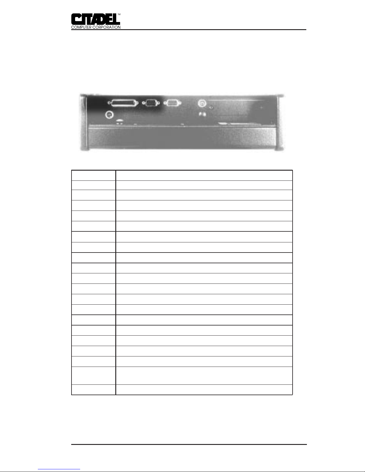
Figure 6. Rear Panel Connectors
DC Power Connector
The DC power connector is a locking 3-pin connector that
accepts +12VDC from either a wall-mounted power supply in
fixed-mount installations, or the DC power converter in mobile,
wireless installations.
32
1
Figure 7. DC Power Connector Pinout
Pin Signal
1 No connection
2 GND (+12V return; NOT chassis ground)
3 +12VDC
Table 1. DC Power Connector Pinout
2 - INSTALLATION & MAINTENANCE
15
TS3000/TS4000 TouchStar Systems User Manual
LPT1 – Enhanced Parallel Port
The LPT1 printer port is an enhanced parallel port with a 25-pin
(DB25) female connector. It provides bi-directional data commu-
nications. Line printers and floppy drives are connected to the
TouchStar via this parallel port.
Figure 8. LPT1 Parallel Port Connector Pinout
Pin Signal
1 PSTB; data strobe
2 PLD0; data 0
3 PLD1; data 1
4 PLD2; data 2
5 PLD3; data 3
6 PLD4; data 4
7 PLD5; data 5
8 PLD6; data 6
9 PLD7; data 7
10 PACK; acknowledge
11 PBUSY; busy
12 PPE; paper end
13 PSLCT; printer selected
14 PAFD; auto feed
15 PERR; printer error
16 PINIT; printer initialized
17 PSLIN; printer select
18-23 Ground
24 Ground; parallel not floppy; connect to +5V to switch
the EPP to the floppy mode
25 Ground
Table 2. LPT1 Parallel Port Connector Pinout
INSTALLATION & MAINTENANCE - 2
16
TS3000/TS4000 TouchStar Systems User Manual
Serial Communication Ports
The TouchStar provides two serial ports, labeled COM1 and
COM2. These ports are used to connect devices such as serial
printers, a mouse, an external modem, or to make a serial
network connection. If factory configured to do so, either serial
communication port can also support a serial bar code scanner.
Each is a 9-pin (DB9), DOS-compatible, RS232C serial port, each
with its own address. Each port occupies two input/output
locations. The maximum supported data rate for serial channel
operation through any of these ports is programmable up to
115.2Kbaud. The serial controller tied to these ports conforms to
the UAR/T industry-standard PC16550 device architecture
(including 16-byte FIFOs) with fully independent baud rate
generation.
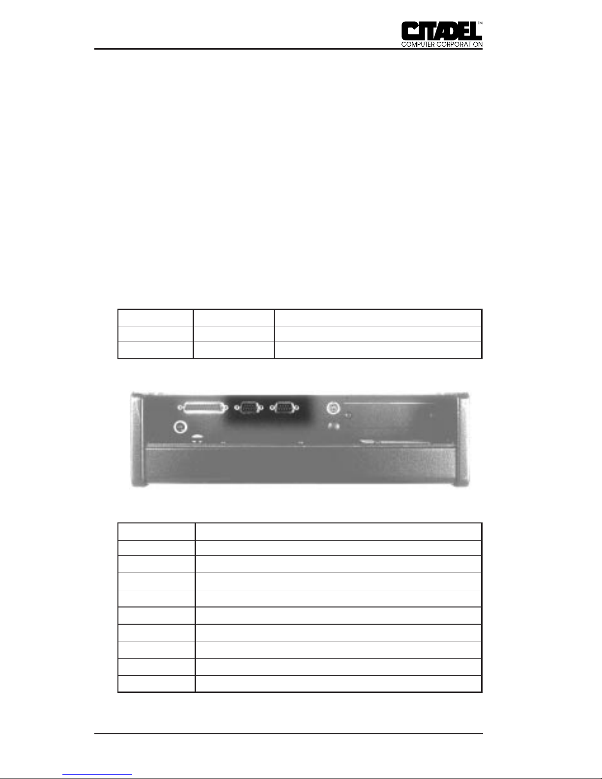
Port Base I/O IRQ
COM1 03F8 4
COM2 02F8 3
Table 3. Serial Port Configuration
Figure 9. Serial Port (DB9) Connector Pinout
Pin Signal
1 DCD; data carrier detect
2 RXD; receive data
3 TXD; transmit data
4 DTR; data terminal ready
5 GND; ground
6 DSR; data set ready
7 RTS; request to send
8 CTS; clear to send
9 RI; ring indicator
Table 4. Serial Port Connector Pinout
2 - INSTALLATION & MAINTENANCE
17
TS3000/TS4000 TouchStar Systems User Manual
Keyboard Port
The keyboard connector is a IBM PS/2 standard, 6-pin mini-
DIN connector. This connector accepts an optional traditional
ASCII keyboard. Wedge-type barcode scanners should be
connected to this port; the (optional) keyboard should then be
plugged into the barcode scanner.
Figure 10. Keyboard DIN Connector Pinout
Pin Signal
1 Keyboard data
2 No connection
3 Ground
4 +5V
5 Keyboard clock
6 No connection
Table 5. Keyboard 6-pin DIN Connector Pinout
PCMCIA Slots
The TouchStar is supplied with dual PCMCIA slots which
provide an interface for portable memory cards, miniature disk
drives, modems, fax/modem cards, and network connections.
The TouchStar system software is provided with the appropriate
PCMCIA drivers which work with all operating systems sup-
ported by the TouchStar. The TouchStar’s two PCMCIA slots
each contain a standard 68-pin PCMCIA connector, and can
accept both Type II (add-on devices such as Flash Cards,
modems and network adapters) and Type III (miniature disk
drive interface) cards. PCMCIA Type I (SRAM) cards are also
supported. Memory and storage cards will typically appear on
the system as drive D:\ or E:\.
INSTALLATION & MAINTENANCE - 2

18
TS3000/TS4000 TouchStar Systems User Manual
PCMCIA cards are inserted into Slot 0 (lower) or Slot 1 (upper)
on the rear panel by holding the card with the connector facing
toward the slot and sliding the card into the slot until firmly
seated. System access of the card can be verified under the
operating system software.
Antenna Connection
TouchStar systems configured with the 2.4GHz spread-spec-
trum transceiver for wireless operation can be supplied with
patch or “rubber duck” type antennas. Antenna connections
may be made to connectors mounted on the case or internally,
depending on the specific system configuration. All antenna
connections use non-standard connectors to prevent antenna
substitution and subsequent violation of FCC regulations.
MAINTENANCE
The TouchStar computer is designed to operate normally in
industrial environments which may contain high levels of
airborne contaminants including dirt and smoke. Periodic
cleaning of the TouchStar is recommended to remove build-up
of foreign substances on the case and touchscreen. Before
cleaning the TouchStar, remove power from the unit. Wipe
accumulated dirt and dust from the aluminum case with a
slightly dampened cloth, paying particular attention to the
angled edge of the bezel. Clean the touchscreen with a commer-
cial brand of computer screen cleaner and a soft, damp cloth, or
compressed air.
2 - INSTALLATION & MAINTENANCE

19
TS3000/TS4000 TouchStar Systems User Manual
BASIC OPERATION ___________________________ 3
POWER-UP
Before powering up the TouchStar for the first time, be sure it is
securely mounted, that all cable connections have been made,
and that the DC power cable is securely attached to the DC
connector on the rear panel.
The TouchStar computers do not have an ON/OFF switch. Both
models will power up immediately when they receive incoming
electrical power. It is important to make all peripheral connec-
tions BEFORE powering up the TouchStar system.
To turn on the TS3000, plug the wall-mounted power supply
into a surge-protected 110VAC outlet. To eliminate potential
damage to the TS3000, be sure the power supply is removed
from the wall outlet before connecting or disconnecting the
power cord to the rear panel.
To turn on the TS4000, turn the DC power converter ON/OFF
switch to ON.
BOOTING-UP
Upon receiving electrical power, the TouchStar will boot up
immediately with no action required. On power up, the
TouchStar conducts a power-on self-test, runs the hardware
initialization program, and then boots DOS. (If your system
does not boot, or does not have a factory-installed version of
DOS, refer to the following section, “Installing the DOS Operat-
ing System”.) The system then processes the config.sys and
autoexec.bat start-up files from the boot drive, which is typi-
cally the Flash Drive (C:\). When the boot process is completed,
the C:\ prompt is displayed on the screen. If Windows is
installed, the system will then load the Windows graphical user
interface.
Memory and storage cards appear as unique drives under the
TouchStar operating system. Their drive designation depends
on the particular card and the PCMCIA slot in which it is
installed.
This manual suits for next models
1
Table of contents


