Citronic Z-2M User manual

™
1
Z-2M & Z-2MR Installation Manual
Includes Zone Remote Installation
Z-2M Dual Zone Mixer Code 953.003
Z-2MR Dual Zone Mixer & Remotes Code 953.009

™
2
The Z-2M & Z-2MR Dual Zone Mixers
The Z-2M & Z2MR are high quality zone mixers that
are easy to operate while extensive enough in their
installer features. With many years of experience in
the manufacturing of zoning systems for leisure
applications at Citronic we know how important it is
to make our devices operator friendly. The Z-2M &
Z2MR are no exception.
The simple user controls belie the
extensive installer options that are either mounted
on the rear panel or hidden below the top cover,
which cannot be accessed while the mixer is
mounted on in a rack. All the equalisation,
sensitivity and priority controls are installer
accessible only. Full details of which are explained
in the body of this manual.
There are 5 inputs in total; Microphone,
three line and a priority. The priority input can be
used as a fourth line input by engaging it on the
front panel while the other inputs are switched off.
All of these inputs have their own gain control
mounted on the rear panel.
Both of the output zones are balanced
stereo low impedance. There is also a mono
selector switch for each of these outputs.
The rear panel is completed by provision
for the connection of expansion modules to
increase the number of zones (up to six), access
for the remote control option and an IEC AC power
connector.
The user controls for each output zone are
simple. There is a rotary selector switch to select
the input, a microphone level control, a music level
control and a button to activate the priority music
input.
The music channels have an Eq auto
loudness control that maintains the equalisation
settings you set across a wide variation in volume
settings. Normally you would need to increase the
bass in a music signal as you decrease the
volume to maintain the apparent listening balance
between high and low frequencies. In this system
it is not necessary. Simply set up the Eq you wish
at the highest volume setting and the system will
re-balance it for lower volumes.

™
3

™
4
WARNING: In order to obtain the best service from the unit we STRONGLY recommend that you read this
manual before you apply any power.
Front Panel Controls Z-2M
1) AC Power Switch
Switches on or off the AC power to the unit and any expander units that may be plugged into it.
2) Power LED
Indicates green when the power switch is on.
3) Zone 1 (or 2) Input Selector Switch
In position off, (as illustrated) all the music inputs are defeated, the possible exception is the priority input, which is
explained below.
In position Line 1, 2 or 3 the zone output will carry the selected source. The inputs can be labelled to indicate the source.
4) Music Priority Inputs
This switch selects the music source connected to the priority input, and the LED will illuminate to indicate this. The priority
input sensitivity and release times must be set up at the time of installation for this function to operate correctly.
When this function is selected and a signal is present on the input, any music playing on input selected by the selector
switch will be overridden and replaced by the priority input signal. If no other inputs are selected, i.e. the selector switch is
in the “off” position the priority input acts as another ordinary line input. See the section in installer set up on sensitivity
control as this must be set up for the system to work properly.
5) Input Zone Labelling
Spaces are provided to label the zone inputs for the users information.
6) Music Level
This control alters the volume of the music in its associated output zone. It is an overall level control for the zone treating
all inputs the same. To cater for different input levels refer to the rear panel level controls detailed in section (12)
7) Microphone Level
This controls the microphone level in the appropriate zone. This control when set at minimum, will defeat the override
depth to the music signal.
Installation Notes:
The Z-2M & Z-2MR are quick and easy to install using conventional connectors. It’s a good idea to double check all
your interconnections as the Z-2M & Z-2MR will only perform to their optimum if the inputs and outputs are properly made.
Always use good quality connectors such as Neutrik® it’s a small investment that can save your time and money.
Connecting Up
8) Microphone Input
The microphone input is balanced. If you wish to use an unbalanced microphone, short pin 3 to pin 1 (ground) and
connect the signal input pin 2. This microphone has first priority in the system and will override the music signals. Full
details of the override control and EQ settings are detailed in the next section (installer Settings).
9) Microphone Gain
This control alters the input gain of the microphone circuit in order to match the output from the microphone. Adjust this
control so that the microphone level control on the front of the Z-2M provides the required volume range. Reduce this
control if distortion occurs.
10) Alarm Detector
This feature allows you to interface this audio system with the alarm system of the venue. All that is required to detect an
alarm condition is that the two terminals are shorted. The associated push button allows you to choose whether the music
signals are reduced by 25dB or 40dB in the alarm condition.
Note: The microphone input is unaffected by this attenuation so that announcements can still be made.
Note: The terminal you can see unplugs from the unit so that the wiring can be completed remotely as access to the back
of the rack is sometimes awkward. These terminals need to be shorted together by an external relay in the alarm system.
11) Zone Expansion Socket
It is possible to add zones to the system by the addition of Citronic’s Z-2X or Z-4X expanders. This socket makes
interconnection simple and is for the ribbon cable supplied with the expanders.
12) Input Gain Control
Because the inputs of various equipment like CD players and tape decks vary so much the Z-2M & Z-2MR are fitted with
input gain control so that you can match the varying inputs to give the same volume level control range from the music
level control on the front panel or Remote.
13) Input Sockets
Two Phono (RCA Phono jack) connectors for your music input device. This device can be virtually any source, e.g. CD
player, tape deck or satellite feed. If your music source is mono connect to the left and the right input using a proprietary
Phono splitter cable or connector.
™
5
14) Priority Input
This is a special input that will override the music playing in any of the other inputs and automatically route whatever is on
the input to the output. This is especially useful for jukeboxes where the background music from another input is required
when the jukebox is not in use. The sensitivity of the auto signal detect circuit can be altered, see the next section:
Installer Options.
15) Priority Gain Control
This works the same as all the other input gain controls. See feature 5 above.
16) Remote Control Option
This is a blanking plate that needs to be removed if you choose to add the remote control option on the Z-2M. It will need
to be removed for the Z-2MR. Installation of the remote controls will be explained later in the manual. For the Z-2M you
can purchase the remotes as an addition using the part code 953.006
17 & 19) Zone 1 Output
The zone outputs are balanced to minimise noise pickup. A bar environment can be electrically noisy and proximity to
beer coolers and automated pumps may be difficult to avoid. These electronically balanced outputs will reject this kind of
electrical noise and keep the sound system clean of pops and crackles. In the unlikely event you have to use a domestic
HI Fi type amplifier that does not have a professional standard input connect its input to pin 2 (+) and 1 (Ground). In this
mode the output level is lower and better suited to domestic amplifiers, which have a much higher input sensitivity. NB do
not use Pin 3, leave it floating but, also note, you may suffer from electrical noise pickup.
18) Zone 1 Mono Button
If the zone is to be powered using a mono amplifier activating this button will mix the left and right channels and provide a
mono output from both connectors.
20 & 22) Zone 2 Outputs
As per Zone 1 output.
21) Zone 2 Mono Button
As per Zone 1 mono button.
23) AC Power Socket
A standard IEC AC power socket for connecting to the main AC supply. Use only the AC mains power lead supplied with
the unit and check that the supply voltage matches the rating uppermost on the fuse mounted on the socket. This unit is
designed to operate at 220 or 230V (Europe & Asia).
Installer Settings
The Z-2M & Z-2MR have features which are set up by the installer at the time of installation and then secured so that
unskilled operators do not inadvertently re-configure the system and prevent it operating as expected. This sections deals
with these options and how to adjust them.
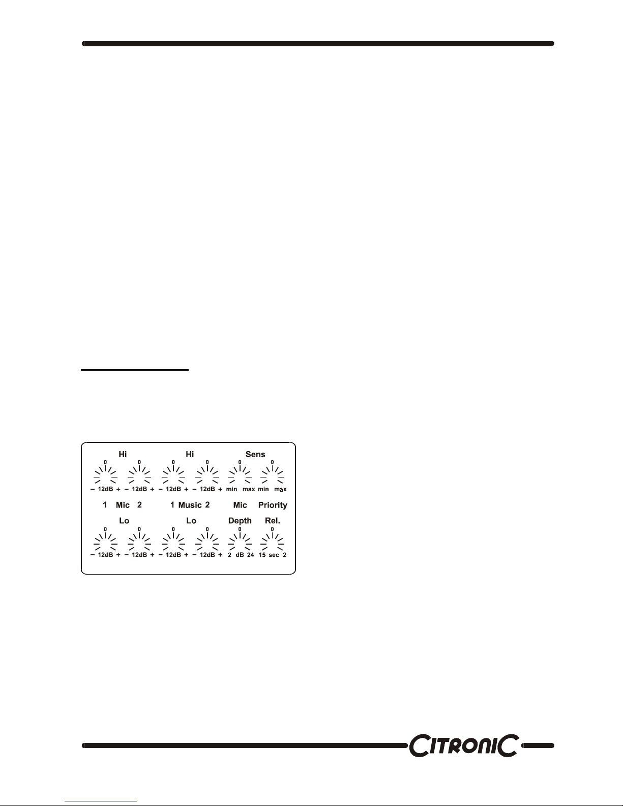
The illustration shows how the installer adjustment options appear on the top cover of the mixer.
Microphone Eq
The microphone Eq is separate for each zone. The reason for this is because the nature of the zones can be quite different
in application as well as in acoustic properties. E.g. Zone one could be a restaurant where the ambient noise is low and the
decor is likely to have soft surfaces that will dampen the acoustic reflections while zone two could be a pool hall where the
ambient noise could be high and the acoustics more reflective. To ensure that speech is intelligible the Eq settings in these
two zones need to be quite different.
The first control is the Eq Hi for zone 1 and the second the Eq Hi for zone 2. Below these controls are the corresponding Lo
band Eq controls. Each of these controls provide ± 12dB of lift and cut.
Music Eq
Next there is a similar set of Eq controls for the music signals. Again these are separate for each zone and there is both Hi
and Lo Eq available at ±12dB.
To gain access to these controls the top panel will
need to be removed, use the diagram also printed
on the top panel as a guide to the controls.
Once the settings have been made, replace the
top panel and mount into a rack, this will prevent
any tampering with the system by the user.
We’ll start to explain the settings from top left and
work through them by function.
This manual suits for next models
1
Table of contents
Other Citronic Music Equipment manuals


