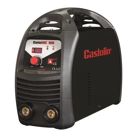
Castolin CastoMatec RCD 400 User manual

GB - USER’S GUIDE
F - GUIDE DE L’UTILISATEUR
RCD
400
RCD
600
RCD
850
Ed.05/2012

2
GB - The machine you have just acquired has taken advantages, in its production, of the wide experience in the manufacturing
of welding machines, along with the latest power electronics technologies. It will give you entire satisfaction for years if you
respect all the operating and maintenance instructions given in this manual. We strongly suggest reading very carefully the
chapters concerning security and individual protection before using this machine.
1. SAFETY INSTRUCTIONS 3
2. DESCRIPTION 6
3. TECHNICAL DATA 7
4. INSTALATION / FUNCTIONNING 8
5. ELECTRIC SCHEMA 10
6. SPARE PARTS LIST 11
7. MAINTENANCE 13
F - La machine que vous venez d’acquérir a bénéficié dans sa réalisation de la grande expérience du fabricant dans la conception et la
fabrication de matériels de soudage, ainsi que des derniers progrès techniques en électronique de puissance.
Cette machine vous donnera entière satisfaction pour nombreuses années si vous respectez les conditions d’emploi et d’entretien décrites
dans ce manuel. Nous vous recommandons également la lecture attente des chapitres consacrés à la sécurité et à la protection individuelle
avant d’utiliser cet’ appareil.
1. INSTRUCTIONS DE SÈCURITÉ 14
2. DESCRIPTION 17
3. CARACTERISTIQUES 18
4. MISE EN MARCHE / FONCTIONNEMENT 19
5. SCHEMA ELECTRIQUE 21
6. NOMENCLATURE 22
7. MAINTENANCE 24

3
GB - USER’S MANUAL
1. SAFETY INSTRUCTIONS
In its conception, specification of parts and production, this machine is in compliance with regulation in force, namely
the European Standards (EN) and internationals (IEC).
There are applicable the European Directives “Electromagnetic compatibility” and “Low voltage”, as well as the standards IEC
60974-1 / EN 60974-1 and IEC 60974-10 / EN 60974-10.
1.1 ELECTROMAGNETIC COMPATIBILITY
The user is responsible for installing and using the arc welding equipment according to the manufacturer’s instructions.
If electromagnetic disturbances are detected, then it shall be the responsibility of the user of the arc welding equipment to
resolve the situation with the technical assistance of the manufacturer. In some cases this action may be as simple as connect to
earth the welding circuit. In other cases it could involve constructing electromagnetic screens enclosing the welding power
source and the work complete with associated input filters. In all cases, electromagnetic disturbances shall be reduced to the
minimum to avoid troubles.
Before installing arc welding equipment the user shall make an assessment of potential electromagnetic problems in
the surrounding area. The following shall be taken into account:
a) Supply cables, control cables, signaling and telephone cables, above, below and adjacent to the arc welding equipment;
b) Radio and television transmitters and receivers;
c) Computer and other control equipment;
d) Safety critical equipment, e.g. guarding of industrial equipment;
e) The health of the people around, e.g. the use of pacemakers and hearing aids;
f) Equipment used for calibration or measurement;
g) The immunity of other equipment in the environment. The user shall ensure that other equipment being used in the
environment is compatible. This may require additional protection measures;
h) The hour of day when welding or other activities are to be carried out.
1.1.1 Methods of reducing emissions
Connection to mains
Arc welding equipment should be connected to the input supply system according to the manufacturer’s
recommendations. If interference occurs, it may be necessary to take additional precautions such as filtering of the supply
system. Consideration should be given to shielding the supply cable of permanently installed arc welding equipment, in
metallic conduit or equivalent. Shielding should be electrically continuous throughout its length. The shielding should be
connected to the welding power source so that good electrical contact is maintained between the conduit and the welding
power source enclosure.
Welding cables
The welding cables should be kept as short as possible and should be positioned close together, running at or close to
the floor level.
Equipotent bonding
Bonding of all metallic components in the welding installation and adjacent to it should be considered. However,
metallic components bonded to the work piece will increase the risk that the operator could receive an electric shock by
touching these metallic components and the electrode at the same time. The operator should be insulated from all such bonded
metallic components.
Work piece earth connection
When the work piece is not bonded to earth for electrical safety, nor connected to earth because of its size and
position, e.g. ships hull or building steelwork, a connection bonding the work piece to earth may reduce emissions in some, but
not all instances. Care should be taken to prevent the earthling of the work piece increasing the risk of injury to users,
or
damage
to other electrical equipment. Where necessary, the connection of the work piece to earth should be made by a direct
connection to the work piece, but in some countries where direct connection is not permitted, the bonding should be
achieved by
suitable capacitance, selected according to national regulations.

4
Screening and shielding
Selective screening and shielding of other cables and equipment in the surrounding area may alleviate problems of
interference. Screening of the entire welding installation may be considered for special applications.
1.2 ELECTRICAL SECURITY
1.2.1 Connection to the network
Before connecting your equipment, you must check that:
- The meter, the safety device against over-currents, and the electrical installation are compatible with the maximum power and
the supply voltage of the welding power source (refer to the instructions plates).
- The connection, either single-phase, or three-phase with earth can be effected on a socket compatible with the welding power
source cable plug.
- If the cable is connected to a fixed post, the safety device against electric shocks will never cut the earth.
- The ON/OFF switch located on the welding power source is turned off.
1.2.1 Working area
The use of arc welding implies a strict respect of safety conditions with regard to electric currents. It is necessary to
check that no metal piece accessible by the operators and to their assistants can come into direct contact with a phase conductor
and the neutral of the network. In case of uncertainty, this metal part will be connected to the earth with a conductor of at least
equivalent section to the largest phase conductor.
Make sure that all metal pieces that the operator could touch with a non insulated part of his body (head,
hands
without
gloves on, naked arms, etc) is properly grounded with a conductor of at least equivalent section to the biggest supply
cable of the ground clamp or welding torch. If more than one metal ground is concerned, they need to be all interlinked in one,
which must be grounded in the same conditions.
Unless very special care have been taken, do not proceed to any arc welding or cutting in conductive enclosures,
whether it is a confined space or the welding machine has to be left outside. Be even more prudent when welding in humid or
not ventilated areas, and if the power source is placed inside (Decree dated 14.12.1988, Art. 4).
1.2.3 Risks of fire and explosion
Welding can originate risks of fire or explosion. You have to pay attention to fire safety regulation
- Remove flammable or explosive materials from welding area;
- Always have sufficient fire fighting equipment;
- Fire can break out from sparks even several hours after the welding work has been finished.
1.3 INDIVIDUAL PROTECTION
1.3.1 Risks of external injuries
Arc rays produce very bright ultra violet and infrared beams. They will damage eyes and burn skin if the operator is
not properly protected.
-The welder must be dressed and protected according to the constraints of his works impose to him.
-Operator must insulate himself from the work-pieces and the ground. Make sure that no metal piece, especially those
connected to the network, comes in electrical contact to the operator.
-The welder must always wear an individual insulating protection.
Protective equipments: gloves, aprons, safety shoes that offer the additional advantage to protect the operator against
burns caused by hot pieces, spatters, etc. Check the good state of this equipment and replace them before you are not protected
any more.
- It is absolutely necessary to protect eyes against arc rays.
- Protect hair and face against sparks. The welding shield, with or without headset, must be always equipped with a proper
filter according to the arc welding current. In order to protect shaded filter from impacts and sparks, it is recommended to add a
glass in front of the shield.

5
The helmet supplied with the equipment is provided with a protective filter. When you want to replace it, you must
precise the reference and number of opacity degree of the filter. Use the shade of lens as recommended in the following table
(opacity graduation).
Protect others in the work area from arc rays by using protective booths, UV protective goggles, and if necessary, a
welding shield with appropriate protective filter on (NF S 77-104 – by A 1.5).
Current
Amps
0,5
2,5
10
20
40
80
125
175
225
275
350
450
Welding process
1
5
15 30 60 100150200250300400500
Coated electrodes
9
10
11
12
13
14
MIG on heavy metals
10
11
12
13
14
MIG on light alloys
10
11
12
13
14
15
TIG on all metals
9
10
11
12
13
14
MAG
10
11
12
13
14
15
Air/Arc gouging
10
11
12
13
14
15
Plasma cutting
9
10
11
12
13
Depending on the conditions of use, the next highest or lowest category number may be used.
The expression “heavy metals” covers steels, alloyed steels, copper and its alloys.
The shaded areas represent applications where the welding processes are not normally used at present. .
NOTE: Use a higher degree of filters if welding is performed in locations which are not well lighted.
1. 3.2 Risk of internal injuries
Gases and fumes
- Gases and fumes produced during the welding process can be dangerous and hazardous to your health. Arc welding
works must be carried out in suitable ventilated areas.
- Ventilation must be adequate to remove gases and fumes during operation. All fumes produced during welding have
to be efficiently removed during its production, and as close as possible from the place they are produced.
- Vapors of chlorinated solvents can form toxic gas phosgene when exposed to ultraviolet radiation from an electric
arc.
Safety in the use of gases (welding with TIG or MIG inert gases)
Compressed gas cylinders
Compressed gas cylinders are potentially dangerous. Refer to suppliers for proper handling procedures:
- No impact: secure the cylinders and keep them away from impacts.
- No excess heat (over 50°C)
Pressure relief valve
- Check that the pressure relief screw is slackened off before connecting to the cylinder.
- Check that the union is tight before opening the valve of the cylinder. Open it slowly a fraction of a turn.
- If there is a leak, NEVER tighten a union under pressure, but first close the valve on the cylinder.
- Always check that hoses are in good condition.

6
Fig. 2
2Machine under voltage indicator
6
Ammeter
3
MMA/TIG (Mod. 400) or MMA/TIG/ARC
(Mod. 600 and 850) selector
-AIR
Voltmeter
4LOCAL/REMOTE adjustment selector
8
ARC FORCE adjustment button
2. DESCRIPTION
400, 600 and 850 models are MMA (coated electrode) and TIG (with torch with valve) welding rectifiers. 600 and
850 models allow ARC-AIR gouging and cutting. Current adjustment is tiristorized and effectuated locally or remotely at
distance.
They allow welding of all kinds of electrodes (400 model until 6 mm diameter and 600 and 850 models until 8 mm
diameter) and TIG (for mild steels, stainless steels, copper and brass).
All models are equipped with a 230V 2200V
single-phased socket, located on the rear
panel, for electric tools, econoTIG and high
frequency generator for TIG welding
connection.
Attention: do not plug or use any electric
tool during welding procedure.
Fig. 1
FRONT PANEL
1 Thermal protection indicator 5
Welding current adjustment button (400 model) or
welding current and ARC AIR cutting (600 and
850 models)
7

7
Technical data
Un.
Electrode diameter
Ø mm
6.0
Current plug
V / VA
230 VAC 2200 VA
Weight
Kg
190
Dimensions
cm
78 x 67 x 98 *
Technical data
Un.
Electrode diameter
Ø mm
8.0
Current plug
V / VA
230 VAC 2200 VA
Weight
Kg
230
Dimensions
cm
78 x 67 x 98 *
Technical data
Un.
Electrode diameter
Ø mm
8.0
Current plug
V / VA
230 VAC 2200 VA
Weight
Kg
270
Dimensions
cm
78 x 67 x 98 *
3. TECHNICAL DATA
Mod. 400
Mod. 600
Mod. 850
* Dimensions without pole

8
4. INSTALATION
4.1 CONNECTION TO THE MAIN SUPPLY
This unit must be connected to a three-phase 230V or 400V - 50 Hz/60 Hz + ground.
Main supply must be protected by fuses or circuit breaker according to the value I1eff written on the specifications of
the power source.
It is strongly suggested to use a differential protection for the operator’s safety.
4.2 CONNECTION TO EARTH
Norms).
For the operator's protection, the power source must be correctly grounded (according to the International Protections
It is absolutely necessary to set a good earth connection with the green/yellow wire of the power cable. This will avoid
discharges caused by accidental contacts with grounded pieces. If no earth connection has been set, a high risk of electric
shock through the chassis of the unit remains possible.
4.3 MMA WELDING
- Make the necessary connections to mains and earth as described in “Installation”. Connect the earth and electrode
holder to welding plugs + (positive) and – (negative) according to electrode polarity and with electrodes manufacturer
instructions.
- Switch on the welding set.
At the beginning, the orange led indicator lights on and immediately turns off if there is no default.
The red indicator lights on, indicating that the welding set is under voltage.
1 – Select MMA in MMA\TIG 2T \TIG 4T selector ( indicator lights on).
2 – Select the desired position in Local/Remote selection button: Adjust current in the current adjustment potentiometer
or in the remote control or foot pedal to the desired current value.
Note: When using remote control or pedal, current variation is effectuated between the minimum value of the machine
and the value set on the machine.
Adjust welding current according to the following table:
Electrode diameter (mm)
2,0
2,5
3,2
4,0
5,0
6,0
8,0
Welding current (Amp)
50 - 70
60 - 100
80 - 150
130 - 200
150 - 260
200 - 360
360 - 600
3 – Adjust ARC FORCE (initial pick current to facilitate arc ignition).
4 – If necessary, during welding operation, adjust the current value.
4.4 TIG WELDING
- Make the necessary connections to mains and earth as described in “Installation”. Connect the earth cable to welding
plug + (positive) and torch TIG to welding plug – (negative) .
- Switch on the welding set.
At the beginning, the orange led indicator lights on and immediately turns off if there is no default.
The red indicator lights on, indicating that the welding set is under voltage.
1 – Select TIG in MMA / ARC-AIR (Mod. 600 and 850) / TIG selector ( indicator lights on).
2 – Adjust Local/Remote selector (TIG): Adjust current in the current adjustment potentiometer or in the remote
control or foot pedal to the desired current value.

9
Note: When using remote control or pedal, current variation is effectuated between the minimum value of the machine
and the value set on the machine.
3 - Adjust welding current according to the following table:
4 – If necessary, during welding operation, adjust the current value.
4.5 ARC-AIR CUTTING (Mod. 600 and 850)
- Make the necessary connections to mains and earth as described in “Installation”. Connect the earth cable to welding
plug – (negative) and ARC-AIR electrode holder to welding plug + (positive).
- Switch on the welding set.
At the beginning, the orange led indicator lights on and immediately turns off if there is no default.
The red indicator lights on, indicating that the welding set is under voltage.
1 – Select ARC-AIR in MMA\ARC-AIR (Mod. 600 and 850) \TIG selector ( indicator lights on).
2 – Adjust Local/Remote selector (TIG): Adjust current in the current adjustment potentiometer or in the remote
control or foot pedal to the desired current value.
Note: When using remote control or pedal, current variation is effectuated between the minimum value of the machine
and the value set on the machine.
3 - Adjust ARC-AIR current according to the following table:
Electrode
diameter
(Ø
mm)
DC current adjustment, ARC-AIR electrode positive
Minimum current (AMP)Maximum current (AMP)
3.2
60
90
4.0
90
150
4.8
200
250
6.4
300
400
7.9
350
450
9.5
450
600
4 – If necessary, during welding operation, adjust the current value.

>
("")
>
Q
Q
r
3 3
o
-
g
!
T
1111•
1
LIR
LIT
l
11111111114-f
1
1
I
I
t
!
Î
t"'l
t'"'
t"'l
("")
+Qj
T1
......
t'"'
1
1
-n< T2
el
PT
1
1
1
1
·-
1
a=
1
V
out
CS T S'
R'
Cl
Print circuit (components side
view)
J1 J3 J2
.,. ,
,.
,.,
-nen'< enzco
co
wmwmww
::J
0..,..,
(f) (f) (f) (f) (f) (/)
::J
Q
CDCDroCDCD CDO
0..,
;o ;o
en en
--1
--1
rï rï
l
lllllill
A1 - Main
switch
Cl - Print
circuit
F - Socket remote
control
ln -
Inductance
M
-Fan
PT - Tiristors
bridge
::J (/)
-·
z z
-
3
""Tl ""Tl
F
12
Remote
s
- lndicator
+5VDC
SH
-Shunt
10K
GND
1
1
1
1
1
-=-
......
T
-Transformer
ArcForce Remote
0
T1/T2 - Welding
terminais
TM
-
Monof.
plug
+5VDC
R - Resistance 10K
L.
H
GND
GND

11
6. SPARE PARTS LIST
Caster-wheel model:

12
Nr.
Description
1 Lifting support
2 Current adjustment button
3 ARC FORCE adjustment button
4
Tubular pole (tubular poles
model)
5 Handle (tubular poles model)
6 Remote control plug
7 Resistance coil
8 Control circuit
9 Inductance coil
10 Rectifier bridge
11 Ammeter/Voltmeter
12 Plastic panel
13 Quick plug
14 Fan
15 Current plug
16 Transformer
17 230/400V switch
18 Input cable
19 Cable holder
20 Wheel (tubular poles model)
21 Chassis (tubular poles model) Front
panel
Rear panel Right
panel Left panel
Cover
22
Caster wheel (caster wheels
model)
23 Wheel (caster-wheels model)
24 Chassis (caster-wheels model) Front
panel
Rear panel Right
panel Left panel
Cover

13
7. MAINTENANCE
This arc welding equipment should be routinely maintained according to the manufacturers’ recommendations. All
access and service doors and covers should be closed and properly fastened when the arc welding equipment is in operation.
The arc welding equipment should not be modified in any way, except for those changes and adjustments covered in the
manufacturer’s instructions. In particular, the spark gaps of arc striking and stabilizing devices should be adjusted and
maintained according to the manufacturer’s recommendations.
Before carrying out any internal checking or repair work, check that the power source has been disconnected from the
electrical installation by locking and guard devices. Ensure and avoid accidental connection of the plug to a socket.
Voltages
are
high and dangerous inside the machine.
In spite of their robustness, ours power sources require some regular maintenance. Each 6 months (more often in
dusty surroundings):
- The machine must be blown through with dry, oil free compressed air.
- Check for continuity all electrical connections.
- Check the connection of cables and flat top.
Check the good state, insulation and connection of all the equipment and electrical accessories: plugs and flexible
supply cables, conduits, connectors, extension cables, sockets on the power source, ground clamp and electrode holder. These
connections and mobile accessories are marked according to standards, if consistent with the safety rules. They can either be
controlled by you or by accredited firms.
-Repair or replace all defective accessories
-Check periodically that the electrical connections are tightened and do not heat.
Maintenance works of electrical equipment must be entrusted by qualified people (Section VI, Art. 46).
7.1 DAMMAGE REPAIR
POSSIBLE CAUSES
CHECK
YELLOW AND RED INDICATORS ARE OFF = NO SUPPLY
ON/OFF main switch is OFF
Switch it ON
Power supply cable is cut
Check cable and connections
No main supply
Check circuit breaker and fuses
Defective ON/OFF main switch
Replace the switch
YELLOW AND RED INDICATORS ON = INPUT VOLTAGE OVER RATED LIMIT
Incorrect input voltage
Check supply voltage
Power source connected to 1 phase
Connect the machine to proper voltage (3x400V)
YELLOW INDICATOR ON = WARMING UP
Duty cycle over rated (if ambient > 25°C)
Let the machine cool, it will automatically start again
Insufficient cooling air
Clean the air inlets
Very dusty machine
Open the generator and blow it through
Fan doesn’t start
Replace the fan
IMPROPER WELDING
Wrong electrode polarity
Use the right polarity according to the indications of
electrode’s manufacturer
Dirtiness in the weld parts
Clean and eventually degrease the weld parts

14
FR - GUIDE DE L’UTILISATEUR
1. INSTRUCTIONS DE SECURITE
Dans sa conception, spécification des composants et fabrication, cette machine est en accord avec la réglementation
en vigueur, nommément les normes européennes (EN) et internationaux (IEC).
Sont applicables les Directives Européennes «Compatibilité Electromagnétique» et «Baisse Tension», aussi comme
les normes IEC 60974-1 / EN 60974-1 et IEC 60974-10 / En 60974-10.
1.1 COMPATIBILITE ELECTROMAGNETIQUE
Si des perturbations électromagnétiques apparaissent, c’est de la responsabilité de l’utilisateur de résoudre le
problème avec l’assistance technique du constructeur. Dans certains cas, l’action corrective peut se réduire à la simple
connexion à la terre du circuit de soudage. Dans le cas contraire, il peut être nécessaire de construire un écran
électromagnétique autour de la source et de joindre à cette mesure des filtres d’entrée. Dans tous les cas, les perturbations
électromagnétiques devront être réduites jusqu’à ce qu’elles ne soient plus gênantes.
Avant l’installation, l’utilisateur doit estimer les éventuels problèmes électromagnétiques dans la zone environnante.
Les points suivants doivent être pris en compte :
a) Autres câbles d’alimentation, câbles de commande, câbles de signalisation et de téléphone, au-dessus, au-dessous et à
côté de l’équipement de soudage;
b) Emetteurs et récepteurs de radio et télévision;
c) Ordinateurs et autres équipements de contrôle;
d) Sécurité des équipements critiques, notamment la surveillance d’équipements industriels;
e) Santé des personnes alentour, notamment les porteurs de stimulateurs cardiaques et de prothèses auditives;
f) Equipements utilisés pour le calibrage et l’étalonnage;
g) Immunité des autres équipements environnants. L’utilisateur doit s’assurer que ces matériels sont compatibles. Cela peut
exiger des mesures de protection supplémentaires.
h) Heure à laquelle les matériels de soudage et autres équipements fonctionnent.
1.1.1 Méthodes de réduction des émissions
Alimentation
L’équipement de soudage doit être connecté au réseau selon les indications du constructeur. Si des interférences
apparaissent, il peut être nécessaire de prendre des précautions supplémentaires telles que le filtrage de l’alimentation. Il faut
prendre en considération le blindage des câbles d’alimentation des équipements de soudage installés de façon
permanente
dans
des conduits métalliques ou équivalents. Le blindage doit être réalisé en respectant une continuité électrique de bout en
bout. Il doit être connecté à la source de soudage de façon à ce qu’un bon contact électrique soit maintenu entre le conduit
et
la
source de soudage.
Câbles de soudage
du sol.
Les câbles de soudage doivent être aussi courts que possible et placés proches l’un de l’autre, à même le sol ou près
Connexion équipotentielle
On doit prendre en compte les liens entre tous les composants métalliques de l’installation de soudage et adjacents à
cette installation. Cependant, les composants métalliques reliés à la pièce sur laquelle on travaille augmentent le risque de
choc électrique si l’utilisateur touche les composants métalliques et l’électrode en même temps. L’utilisateur doit être isolé de
tous les composants métalliques reliés.
Connexion à la terre
Quand la pièce à souder n’est pas reliée à la terre, soit pour des raisons de sécurité électrique, soit en raison de sa
taille ou de sa position (ex: coque de bateau, aciérie), une connexion reliant la pièce à la terre peut réduire les émissions dans
certains cas. Il faut cependant faire attention à ce que la mise à la terre de la pièce n’augmente pas les risques de blessures
pour l’utilisateur ou n’endommage pas d’autres équipements électriques. Quand c’est nécessaire, la mise à la terre de la pièce
doit s’effectuer par une liaison directe à la pièce mais dans quelques pays où ceci n’est pas autorisé, la liaison doit s’effectuer
par une résistance de capacité et en fonction de la réglementation nationale.

15
Blindage et protection
Le blindage et la protection sélectifs d’autres câbles et matériels dans la zone environnante peuvent limiter les
problèmes d’interférences. Le blindage de toute l’installation de soudage peut être envisagé pour des applications spéciales.
1.2 SECURITE ELECTRIQUE
1.2.1 Raccordement au réseau
Avant de raccorder votre appareil, vérifiez bien que:
- Le compteur, le dispositif de protection contre les surintensités et l'installation électrique sont compatibles avec la
puissance maximale et la tension d'alimentation de votre source de courant de soudage (indiqués sur la plaque signalétique de
l'appareil).
- Le branchement monophasé, ou triphasé avec terre, est réalisable sur un socle compatible avec la fiche du câble de
la source de courant de soudage.
- Si le câble est branché à poste fixe, la terre, si elle est prévue, ne sera jamais coupée par le dispositif de protection
contre les chocs électriques.
- L'interrupteur de la source de courant de soudage, s'il existe, est sur la position "ARRET".
1.2.2 Poste de travail
La mise en ouvre du soudage à l'arc implique le strict respect des conditions de sécurité vis-à-vis des courants
électriques. Il faut s'assurer qu'aucune pièce métallique accessible aux soudeurs et à leurs aides ne peut entrer en contact
direct ou indirect avec un conducteur du réseau d'alimentation. Dans un doute sur ce risque grave, cette pièce métallique sera
reliée à la terre par un conducteur de section électrique au moins équivalente à celle du plus gros conducteur de phase.
Il faut également s'assurer que toute pièce métallique que le soudeur pourrait toucher par une partie non isolée du
corps (tête, main sans gant, bras nu...) est reliée à la terre par un conducteur d'une section électrique au moins équivalente au
plus gros câble d'alimentation de la pince de masse ou torche de soudage. Si plusieurs masses métalliques sont susceptibles
d'être concernées, elles seront reliées en un point, lui-même mis à la terre dans les mêmes conditions.
Vous interdirez, sauf à prendre des mesures très spéciales que vous appliquerez avec une grande sévérité de soudage
et de coupage à l'arc dans des enceintes conductrices, qu'elles soient étroites ou que vous deviez laisser les appareils de
soudage à l'extérieur. A fortiori, vous vous obligerez à prendre des mesures de sécurité très sérieuses pour souder dans les
enceintes peu ventilées ou humides, et si la source de courant de soudage est placée à l'intérieur.
1.2.3 Risques d´incendie et d’explosion
Souder peut entraîner des risques d’incendies ou d’explosion. Il faut observer certaines précautions :
- Enlever tous les produits explosifs ou inflammables de la zone de soudage;
- Vérifier qu’il existe à proximité de cette zone un nombre suffisant d’extincteurs;
- Vérifier que les étincelles projetées ne pourront pas déclencher un incendie, en gardant en mémoire que ces
étincelles peuvent couver plusieurs heures après arrêt du soudage
1.3 PROTECTION INDIVIDUELLE
1.3.1 Risques d’atteintes externes
Les arcs électriques produisent une lumière infra rouge et des rayons ultra violets très vifs. Ces rayons
endommageront vos yeux et brûleront votre peau si vous n’êtes pas correctement protégé.
- Le soudeur à l'arc doit être habillé et protégé en fonction des contraintes de son travail.
- Faîtes en sorte qu'aucune partie du corps des opérateurs et de leurs aides ne puisse entrer en contact avec des
pièces et parties métalliques du circuit de soudage, et à fortiori celles qui pourraient se trouver à la tension du réseau
d'alimentation.
- Le soudeur doit toujours porter une protection isolante individuelle.
Les équipements de protection portés par l'opérateur et ses aides : gants, tabliers, chaussures de sécurité, offrent
l'avantage supplémentaire de les protéger contre les brûlures des pièces chaudes, des projections et des scories.
Assurez-vous également du bon état de ces équipements et renouvelez-les avant de ne plus être protégé.
- Il est indispensable de protéger les yeux contre les coups d'arc (éblouissement de l'arc en lumière visible et les
rayonnements infrarouge et ultraviolet).

16
- Les cheveux et le visage contre les projections. Le masque de soudage, sans ou avec casque, est toujours muni d'un
filtre protecteur spécifié par rapport à l'intensité du courant de l'arc de soudage.
Le filtre coloré peut être protégé des chocs et des projections par un verre transparent situé sur la face avant du
masque.
Le masque prévu avec votre appareil est équipé d'un filtre protecteur. Vous devez le renouveler par les mêmes
références (numéro de l'échelon d'opacité). Voir le tableau ci dessous donnant le numéro d’échelon recommandé suivant le
procédé de soudage.
Les personnes dans le voisinage du soudeur et à fortiori ses aides doivent être protégés par l'interposition d'écrans
adaptés, de lunettes de protection anti-UV et si besoin, par un masque de soudeur muni du filtre protecteur adapté.
Procédé de soudage
Intensité du courant en Ampères
0,5
2,5
10
20
40
80
125
175
225
275
350
450
Techniques associées
1
5
15 30 60 100150200250300400500
Electrodes enrobées
9
10
11
12
13
14
MIG sur métaux lourds
10
11
12
13
14
MIG sur métaux légers
10
11
12
13
14
15
TIG sur tous métaux
9
10
11
12
13
14
MAG
10
11
12
13
14
15
Gougeage air/arc
10
11
12
13
14
15
Coupage Plasma
9
10
11
12
13
Selon les conditions d’utilisation, le numéro d’échelon immédiatement supérieur ou inférieur peut être utilisé.
L’expression “métaux lourds” couvre les aciers, les aciers alliés, le cuivre et ses alliages.
Les zones noircies ci dessus correspondent aux domaines où les procédés de soudages ne sont pas habituellement utilisés
dans las pratiques actuelle de la soudure. .
NOTE : Il faut utiliser un échelon plus élevé si le soudage est effectué avec un éclairement ambiant faible.
1.3.2 Risques d’atteintes internes
Sécurité contre les fumes et les vapeurs, gaz nocifs et toxiques
aérés.
- Les opérations de soudage à l'arc avec électrodes doivent être exécutées sur des emplacements convenablement
- Les fumées de soudage émises dans les ateliers doivent être captées au fur et à mesure de leur production, au plus
près possible de leur émission et le mieux possible, et évacuées directement à l'extérieur. Si vous êtes dans un tel cas, vous
devez vous équiper en conséquence. (Art. R 232-1-7, décret 84-1093 du 7.12.1984).
- Les solvants chlorés et leurs vapeurs, même éloignés, s'ils sont concernés par les rayonnements de l'arc, se
transforment en gaz toxiques.
Sécurité dans l’emploi des gaz (Soudage sous gaz inerte TIG ou MIG)
Stockage sous forme comprimée en bouteille
Conformez-vous aux consignes de sécurité données par le fournisseur de gaz et en particulier :
- pas de choc : arrimez les bouteilles, épargnez leur les coups.
- pas de chaleur excessive (supérieure à 50 °C).
Détendeur
- Assurez-vous que la vis de détente est desserrée avant le branchement sur la bouteille.
- Vérifiez bien le serrage du raccord de liaison avant d'ouvrir le robinet de bouteille. N'ouvrez ce dernier que
lentement et d'une fraction de tour.
- En cas de fuite, ne desserrez jamais un raccord sous pression ; fermez d'abord le robinet de la bouteille.
- Utiliser toujours des tuyauteries souples en bon état.

17
Fig. 2
2. DESCRIPTION
400, 600 et 850 ce sont des redresseurs pour soudage MMA (électrodes enrobés) et TIG (avec torche TIG à valve). Les
modèles 600 et 850 permettent le coupage/gougeage ARC-AIR. Le réglage du courant est effectué par thyristors et est fait
localement ou à distance (optionnellement).
Ils permettent le soudage de tous les types d’électrodes (modèle 400 jusqu’à 6 mm de diamètre et modèles 600 et 850 jusqu’à 8
mm diamètre) et TIG (pour l’acier doux, l'acier inoxydable, le cuivre et le laiton).
Sur le panneau arrière tous les modèles sont
équipés d'une prise monophasée de 230 V
2200 VA pour l'alimentation d'outillage
portatif électrique, l'économiseur de gaz ou
le générateur de haute fréquence pour
soudage TIG.
Il faut faire attention et ne pas utiliser les
outillages électriques pendant le soudage.
Fig. 1
PANNEAU AVANT
1 Indicateur protection thermique 5
Botton de réglage du courant AMP (Mod. 400) ou
de réglage du courant de soudage AMP et coupe
ARC-AIR (Mod. 600 et 850)
2Indicateur machine sur tension
6
Ampèremètre
3
Sélecteur MMA/TIG (Mod. 400) ou
MMA/TIG/ARC-AIR (Mod. 600 et 850)
7
Voltmètre
4Sélecteur pour réglage LOCAL/REMOTE
8
Botton de réglage d’ARC FORCE

18
Caracteristiques
Un.
Diametre d’electrode
Ø mm
6.0
Prise du courant
V / VA
230 VAC 2200 VA
Poids
Kg
172
Dimensions
cm
74 x 67 x 98 *
Caracteristiques
Un.
Diametre d’electrode
Ø mm
8.0
Prise du courant
V / VA
230 VAC 2200 VA
Poids
Kg
230
Dimensions
cm
78 x 67 x 98 *
Caracteristiques
Un.
Diametre d’electrode
Ø mm
8.0
Prise du courant
V / VA
230 VAC 2200 VA
Poids
Kg
270
Dimensions
cm
78 x 67 x 98 *
3. CARACTERÍSTIQUES
Mod. 400
Mod. 600
Mod. 850
* Dimensions sans brancard
* Dimensions sand brancard

19
4. MISE EN MARCHE
4.1 INSTALATION
Le générateur doit être alimenté par une source de tension 230V ou 400V - 50 Hz / 60 Hz triphasée + terre.
L’alimentation doit être protégée par un dispositif de protection (fusible ou disjoncteur) correspondant à la valeur
I1eff donnée sur la plaque de firme de
l’appareil.
Un dispositif de protection différentiel n’est pas obligatoire mais est recommandé pour la sécurité des utilisateurs.
4.2 CONEXION A LA TERRE
Pour la protection des utilisateurs, la source de soudage doit être correctement connectée à l'installation de terre
(REGLEMENTATIONS INTERNATIONALES DE SECURITE).
C’est indispensable de mettre en place une bonne mise à le terre au moyen du conducteur vert/jaune du câble
d'alimentation, afin d'éviter des décharges dues à des contacts accidentels avec des objets se trouvant à la terre. Si la
connexion de terre n'est pas réalisée, un risque de choc électrique par le châssis de l'appareil subsiste.
4.3 SOUDAGE MODE MMA
- Effectuer les connexions au réseau et à la terre (voir chapitre "Installation"). Connecter le câble de masse et porte-
électrodes aux prises rapides + (positive) et – (négative) selon la polarité de l’électrode à utiliser et d’accord les indications
du fabricant.
- Mettre en marche le poste, l’interrupteur ON/OFF sur la position ON.
Le voyant orange s’allume et s’éteinte tout de suite, s’il ne détecte pas aucun défaut.
Le voyant rouge s’allume pour indiquer l’alimentation du poste.
1 – Sélection mode de soudage MMA :
Enfoncer la touche de sélection MMA / ARC-AIR (mod. 600 et 850 ) / TIG pour MMA (voyant s’allume).
2 – Enfoncer la touche de sélection commande Local/Distance (TIG) : Régler le courant de soudage par le
potentiomètre de réglage du courant principal ou par la commande ou pédale a distance pour la valeur désiré.
Note : En utilisant l’option commande à distance manuel pour faire le réglage du courant, la variation est faite entre
le minimum de la machine et la valeur réglée dans la machine.
Régler le courant de soudage en accord la table suivante :
Diamètre d’électrode (mm)
2,0
2,5
3,2
4,0
5,0
8,0
6,0
Courant de soudage (Amp)
50 - 70
60 - 100
80 - 150
130 - 200
150 - 260
360 - 600
200 - 400
3 – Régler l’ARC FORCE (courant de pic initial pour faciliter l’amorçage de l’arc).
3 – Si nécessaire, pendant le soudage, ajuster la valeur du courant.
4.4 SOUDAGE MODE TIG
- Effectuer les connexions au réseau et à la terre (voir chapitre "Installation"). Connecter le câble de masse a prise
rapide + (positive) et le torche TIG au prise rapide – (négative).
- Mettre en marche le poste, l’interrupteur ON/OFF sur la position ON.
Le voyant orange s’allume et s’éteinte tout de suite, s’il ne détecte pas aucun défaut.
Le voyant rouge s’allume pour indiquer l’alimentation du poste.
1 - Enfoncer la touche de sélection MMA / ARC-AIR (mod. 600 et 850) / TIG pour TIG (voyant s’allume).
2 – Enfoncer la touche de sélection commande Local/Distance (TIG): Régler le courant de soudage par le
potentiomètre de réglage du courant principal ou par la commande ou pédale a distance pour la valeur désiré.

20
Note : – En utilisant l’option commande à distance manuel pour faire le réglage du courant, la variation est faite
entre le minimum de la machine et la valeur réglée dans la machine.
Régler le courant de soudage en accord la table suivante :
4 – Si nécessaire, pendant le soudage, ajuster la valeur du courant.
4.5 COUPAGE ARC-AIR (Mod. 600 et 850)
- Effectuer les connexions au réseau et à la terre (voir chapitre "Installation"). Connecter le câble de masse a prise
rapide - (négative) et le porte-électrodes ARC-AIR au prise rapide + (positive).
- Mettre en marche le poste, l’interrupteur ON/OFF sur la position ON.
Le voyant orange s’allume et s’éteinte tout de suite, s’il ne détecte pas aucun défaut.
Le voyant rouge s’allume pour indiquer l’alimentation du poste.
1 - Enfoncer la touche de sélection MMA / ARC-AIR (mod. 600 et 850 ) / TIG pour ARC-AIR (voyant
s’allume).
2 – Enfoncer la touche de sélection commande Local/Distance (TIG) : Régler le courant de soudage par le
potentiomètre de réglage du courant principal ou par la commande ou pédale a distance pour la valeur désiré.
Note : – En utilisant l’option commande à distance manuel pour faire le réglage du courant, la variation est faite
entre le minimum de la machine et la valeur réglée dans la machine.
Régler le courant de ARC-AIR en accord la table suivante :
Diamètre
d’électrode
(Ø
mm)
Réglage de courant DC, électrode ARC-AIR positive
Courant minimum (AMP)Courant maximum (AMP)
3.2
60
90
4.0
90
150
4.8
200
250
6.4
300
400
7.9
350
450
9.5
450
600
4 – Si nécessaire, pendant le soudage, ajuster la valeur du courant.
This manual suits for next models
2
Table of contents
Languages:
Other Castolin Welding System manuals
Popular Welding System manuals by other brands

Lampert
Lampert PUK S450 operating manual

Harbor Freight Tools
Harbor Freight Tools Vulcan Migmax 215 Owner's manual & safety instructions

LOKERMANN
LOKERMANN GRAND TIG 200 DC PFC MV user manual

Furukawa electric
Furukawa electric Fitel S175 user manual

Jackle
Jackle conMIG 300 operating manual

CELETTE
CELETTE EASY DENT 3000 Original manual