CLA-VAL e-Power IP User manual

CLA-VAL e-Power IP
Turbine
Power: 14 W / Voltage: 12 V and 24 V
CLA-VAL Europe www.cla-val.ch [email protected] 1-LIN036UE - 10/13
© Copyright CLA-VAL Europe - Specifications subject to change without notice - no contractual illustrations.
User Manual

CLA-VAL e-Power IP
Turbine
Power: 14 W / Voltage: 12 V and 24 V
CLA-VAL Europe www.cla-val.ch [email protected] 2-LIN036UE - 10/13
© Copyright CLA-VAL Europe - Specifications subject to change without notice - no contractual illustrations.
Table of Contents
1
Information .....................................................................................................................3
1.1Precautions Before Starting.....................................................................................................3
1.2Safety Work on Electrical Box..................................................................................................3
1.3Diagnostic for the LED.............................................................................................................3
1.4General Disclaimer...................................................................................................................3
1.5Environmental Protection.........................................................................................................3
1.6Typography..............................................................................................................................3
1.7Basic Calculation Rules ...........................................................................................................4
2
e-Power Ip properties.....................................................................................................5
2.1Performance ............................................................................................................................5
2.2Description...............................................................................................................................6
2.3Technical Data.........................................................................................................................8
2.4PCB..........................................................................................................................................9
2.5Battery Properties ..................................................................................................................10
2.6Battery Alarm .........................................................................................................................10
3
Commissioning.............................................................................................................10
3.1Mounting Instructions.............................................................................................................10
3.2Quick Start Instruction - LIN036ST (see annex Chapter 7)....................................................10
4
Software and firmware .................................................................................................11
4.1Installation OF driver USB......................................................................................................11
4.2Software / Firmware Update ..................................................................................................11
4.3Firmware Update (Internal Software).....................................................................................12
4.4Software.................................................................................................................................12
4.5Software Description..............................................................................................................12
4.6Changing the Battery Capacity ..............................................................................................14
4.7Forced Charge Modification...................................................................................................14
4.1Manual Turbine Operation .....................................................................................................14
5
Assistance.....................................................................................................................15
6
Maintenance..................................................................................................................16
6.1Battery Replacement..............................................................................................................16
6.1Repair Kit Use........................................................................................................................17
7
Annex.............................................................................................................................17
7.1Quick Start Instruction LIN036ST...........................................................................................17
CLA-VAL e-Power IP
Turbine
Power: 14 W / Voltage: 12 V and 24 V
CLA-VAL Europe www.cla-val.ch [email protected] 3-LIN036UE - 10/13
© Copyright CLA-VAL Europe - Specifications subject to change without notice - no contractual illustrations.
1 GENERAL INFORMATION
1.1 PRECAUTIONS BEFORE STARTING
Before beginning work on site, please take the following material with you:
One screwdriver No. 1.
One battery 9V 6LR61.
Adjustable wrench (Spanner).
Connection to our internet address to update your e-Power IP with the latest version of the Software and Firmware
(chapter 0).
1.2 SAFETY WORK ON ELECTRICAL BOX
Before making any wiring connections in the electrical box, ensure that the isolating valve on the bypass is closed so
that the turbine cannot be engaged. Confirm that the battery is disconnected. Confirm that the LED on the PCB is not
blinking.
Never open the isolating valve on the valve bypass before connecting the battery to the PCB.
1.3 DIAGNOSTIC FOR THE LED
The LED is located on the PCB in the electrical box.
1.4 GENERAL DISCLAIMER
In accordance with our policy of continuous development and improvement, CLA-VAL Europe reserves the right to modify or
improve these products at any time without prior notice. CLA-VAL Europe assumes no liability or responsibility for any errors
or omissions in the content of this document.
1.5 ENVIRONMENTAL PROTECTION
Help to preserve and protect the environment. Recycle used batteries and accessories.
1.6 TYPOGRAPHY
Through this manual, the following typographical conventions and symbols have been adopted to help readability:
a. "Bold": Menu, command, tab and button.
b. BOLD ITALIC: Important information.
c. (1): Number of the reference marks on image.
d. www.cla-val.ch: Internet address.
e. : Some tips.
f. : Warning!
Green blinking: Battery is discharging, Turbine OFF, Solenoid state = 0
Red blinking: Battery is discharging, Turbine ON, Solenoid state = 1
Red solid: PCB error, default, contact CLA-VAL
CLA-VAL e-Power IP
Turbine
Power: 14 W / Voltage: 12 V and 24 V
CLA-VAL Europe www.cla-val.ch [email protected] 4-LIN036UE - 10/13
© Copyright CLA-VAL Europe - Specifications subject to change without notice - no contractual illustrations.
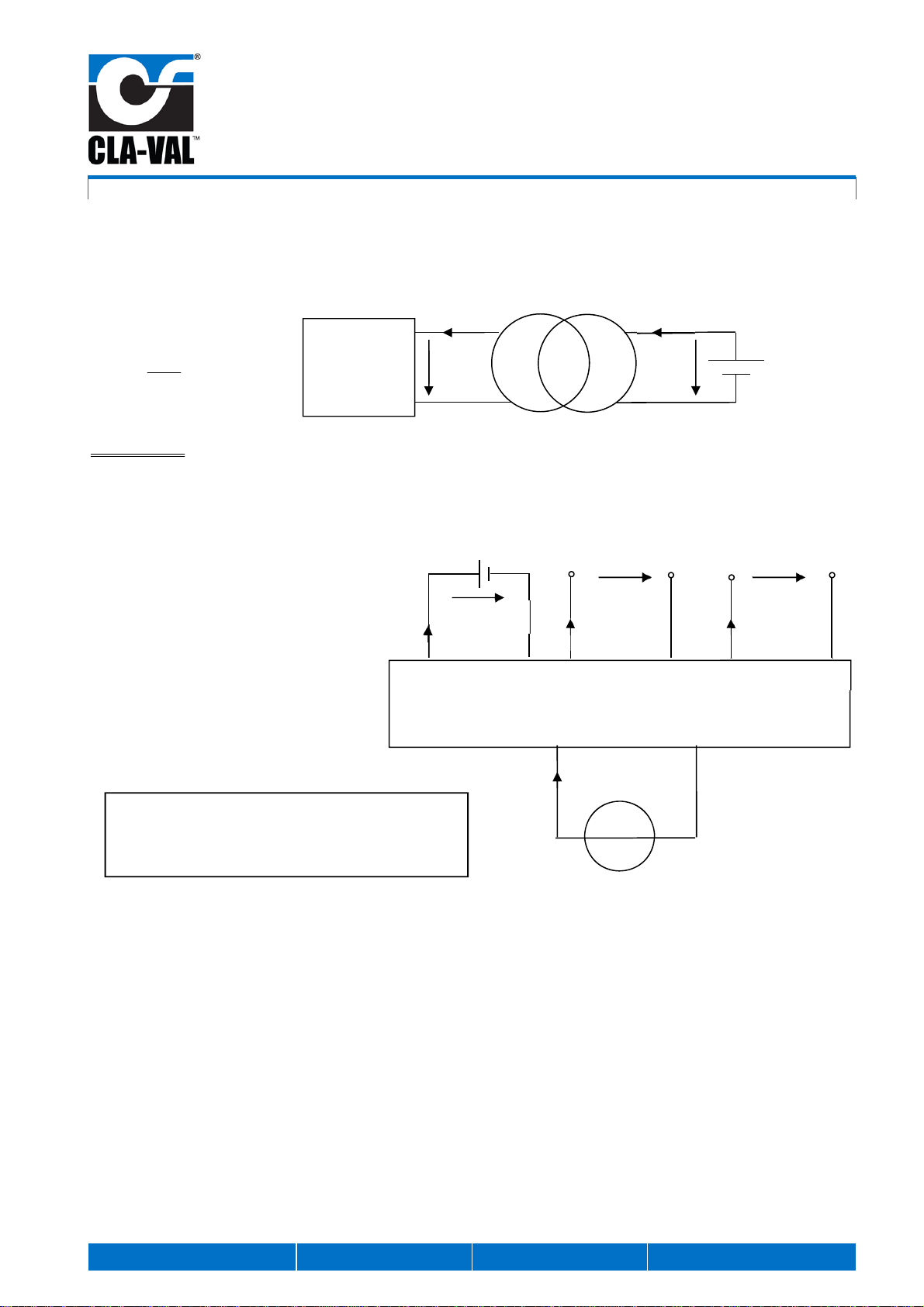
1.7 BASIC CALCULATION RULES
Conversion of the power depending on the voltage:
2
12
2
2
24
24
2412
1212
2412
2412
2424
VV
VV
VV
VV
VV
II
IVP
I
V
P
PP
IVP
The electric current on the load is 2x higher at at 12V than at 24 V, for the same power.
Power balance:- Power balance = Power generated - Power supplied
pliedplied
echbatterygenerated
PP
IUP
supsup
arg
2
2424sup
1212sup
VbatteryVplied
VbatteryVplied
IUP
IUP
I24V
24V 12V
I12V
Load
Battery
Voltage transformer
Sortie 12 VDC
Turbine
IP PCB
Ubattery
Icharge
24 VDC Output
I12V I24V
24V12V
12 VDC Output
Input battery
ech
ech
tAutonomybalancePower
tAutonomybalancePower
arg
arg
:
:
Accumulateur

CLA-VAL e-Power IP
Turbine
Power: 14 W / Voltage: 12 V and 24 V
CLA-VAL Europe www.cla-val.ch [email protected] 5-LIN036UE - 10/13
© Copyright CLA-VAL Europe - Specifications subject to change without notice - no contractual illustrations.
2 E-POWER IP PROPERTIES
Thank you for purchasing a CLA-VAL turbine. With appropriate care, this CLA-VAL e-Power IP will provide power for your
valve for many years. The CLA-VAL e-Power IP is built with the latest technology together with very high quality
components.
The CLA-VAL e-Power IP is an electrical generator using available hydraulic energy directly from the water distribution
network. The e-Power IP is typically installed into the bypass of the CLA-VAL valve.
The e-Power IP powers various devices located within close proximity of the valve or on the valve itself, e.g. motorized
pilots, sensors, telemetry, PLC or HMI interfaces.
2.1 PERFORMANCE
At the optimum operating point of the turbine, (differential Pressure (DP) = 6 mhd and Flow (Q) = 50 l/min).The
rechargeable battery delivers the following output voltage, current and power:
Output
voltages
Amps
continous
(60 min/h)
Amps
peak
(1 min/h)
12 V 1.16 A
14 W 5 A
60 W
24 V
(step-up) 0.58 A
14 W 2.0 A
48 W
The electrical power produced by the e-Power IP charges the battery. The power (W) to charge the battery is the
multiplication of the current (A) and voltage (V). The efficiency between the power supplied by the battery and the power
generated by the turbine is 88%.
Note: The power supplied in the graph above is achieved by optimizing the power supplied by the turbine for each differential pressure.
Mounting Bypass size Head loss
Factory mounting FM
Retrofit mounting RM 1" 3 mhd
3/4" 6 mhd
Wall mounting WM
(for 2x 2 m pipes) 1" 4 mhd
3/4" 9 mhd
Note: Example: For an FM mounting with a body tapping 1" and a bypass pipe 1": 3 m + 6 mhd = total of 9 mhd differential pressure (inlet - outlet of the
valve) to generate 16 W of power by the turbine.
Differential pressure across the turbine [mhd]
Flow
[
l/min
]
50 l/min
6 m
6m
0.0
0.2
0.5
0.7
1.0
1.2
1.5
1.7
0
3
6
9
12
15
18
21
12345678910
133A
Differential pressure across the turbine [mhd]
Current
[
A
]
Power
[
W
]
16 Watts
(generated by the
turbine)
14 Watts
(supplied by the
battery)
CLA-VAL e-Power IP
Turbine
Power: 14 W / Voltage: 12 V and 24 V
CLA-VAL Europe www.cla-val.ch [email protected] 6-LIN036UE - 10/13
© Copyright CLA-VAL Europe - Specifications subject to change without notice - no contractual illustrations.
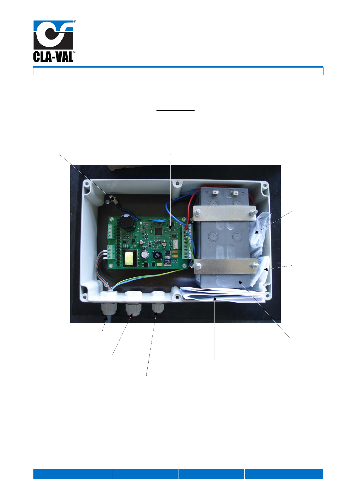
2.2 DESCRIPTION
Electrical box
(factory supplied)
Silicat gel
crystal sachet
Wall mounting
kit
Quick Start Instructions
No LIN036ST
Connection for PC cable e-Power IP PCB
Battery alarm
(dry contact)
Output voltage
12 V and 24 V
Lead acid battery 12 V
(provided not connected)
Turbine
connection

CLA-VAL e-Power IP
Turbine
Power: 14 W / Voltage: 12 V and 24 V
CLA-VAL Europe www.cla-val.ch [email protected] 7-LIN036UE - 10/13
© Copyright CLA-VAL Europe - Specifications subject to change without notice - no contractual illustrations.
e-Power IP
Bistable solenoid, shuts off the
turbine (do not attempt to open
the product as this will
invalidate the warranty)
Hydraulic input
Generator
Filter for solenoid
Terminal for the solenoid and the cable to the
electrical box (do not attempt to open the
product as this will invalidate the warranty)
Hydraulic output
Differential pressure
control protecting cap (do
not attempt to open the
product as this will
invalidate the warranty)
Inside the terminal
(Do not attempt to open the product as this will
invalidate the warranty)
Connection to the
bistable solenoid on the
turbine
Connection to the
electrical box
Factory option:
Connection for a
second bistable
solenoid
USB connection cable
PC connection
Adaptor

CLA-VAL e-Power IP
Turbine
Power: 14 W / Voltage: 12 V and 24 V
CLA-VAL Europe www.cla-val.ch [email protected] 8-LIN036UE - 10/13
© Copyright CLA-VAL Europe - Specifications subject to change without notice - no contractual illustrations.
2.3 TECHNICAL DATA
Electrical Specification
Battery: 12 V
Capacity 3.5 Ah (option 7.0 Ah)
Gelled lead acid waterproof battery VRLA, maintenance free
Battery fully recyclable
Maximum operating temperature 55°C
Power protection:
Reverse polarity & short circuit
80°C stop high temperature
Output 12 VDC:
A continuous 60 min/h 1.16 A (14 W)
A peak 1 min/h 5 A (60 W)
Output 24 VDC: (step-up)
A continuous 60 min/h 0.58 A (14 W)
A high peak 1 min/h 2.5 A (60 W)
Battery alarm output:
Dry contact switch
Operating display:
Charging: LED flashes red
Discharging: LED flashes green
Electrical connection: Moulded 3 meters cable
Temperature range: - 10°C to + 80°C (PCB only)
Other Specifications
Maximum Operating pressure: PFA 10 bar
Valve size and model (mm):
(Piping 3/4" : P- 3/4" )
(Piping 1" : P- 1" )
NGE DN 100 bosses tapped Rp ½" - P ¾"
NGE DN 125-200 bosses tapped Rp ¾" - P ¾"
NGE DN 250-600 bosses tapped Rp 1" - P-1"
GE/AE DN 65-80 bosses tapped Rp ½" - P ¾"
GE/AE DN 100-150 bosses tapped Rp ¾" - P ¾"
GE/AE DN 200-400 bosses tapped Rp1" - P 1"
Software interface: Plug & play / NT / 2000 / XP / Vista / Windows 7 (32 & 64 bit)
Protection: IP 68 (excluding solenoid)
Strainer: For solenoid, Screen 0.2 mm
CLA-VAL e-Power IP
Turbine
Power: 14 W / Voltage: 12 V and 24 V
CLA-VAL Europe www.cla-val.ch [email protected] 9-LIN036UE - 10/13
© Copyright CLA-VAL Europe - Specifications subject to change without notice - no contractual illustrations.
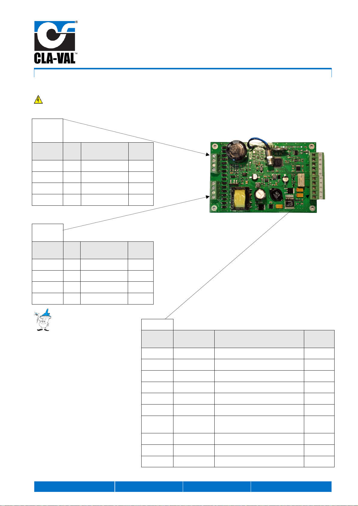
2.4 PCB
THE GENERATOR VOLTAGE REACHES 200 VAC. BE CAREFUL TO SHUT OFF THE ISOLATING VALVE ON THE BYPASS
BEFORE OPENING THE ELECTRICAL BOX.
The connection order of the phases
has no effect on the turbine use
Wiring diagram, please refer to the:
Quick Start Instruction LIN036ST in the
Annex
Terminal
Turbine 2
(option)
.Terminal
No Code Function Color
1 L1
Phase 1 Black
2 L2
Phase 2 Brown
3 L3
Phase 3 Grey
4
No connection
Terminal
Turbine 1
.Terminal
No Code Function Color
1 L1
Phase 1 Black
2 L2
Phase 2 Brown
3 L3
Phase 3 Grey
4
No connection
Terminal 1
.Terminal
No Code Function Colour
1 + 12 VDC Output voltage 12 VDC *
2 - 0 VDC 0 V for 12 VDC output voltage *
3 +24 VDC
Output voltage 24 VDC *
4 - 0 VDC 0 V for 24 VDC output voltage *
5 Alarm
Dry contact battery alarm *
6 Alarm
Dry contact battery alarm *
7 EV+ Output solenoid + Yellow /
Green
8 EV -
Output solenoid - Blue
9 Batt +
Input battery 12 V + Red
10 Batt -
Input battery 12 V - Blue
*Customer wiring
CLA-VAL e-Power IP
Turbine
Power: 14 W / Voltage: 12 V and 24 V
CLA-VAL Europe www.cla-val.ch [email protected] 10 -LIN036UE - 10/13
© Copyright CLA-VAL Europe - Specifications subject to change without notice - no contractual illustrations.
2.5 BATTERY PROPERTIES
The lead acid waterproof battery VRLA (Valve Regulated Lead Acid) is build according to IEC 60896-2 standard for
trouble-free transportation including rail, road, sea and air transportation in accordance with IATA, DGR clause A67.
Lifetime (20°C) is between 5 and 7 years according to the type of use (after 2000 cycles remaining capacity is 80%).
Shipped from factory fully charge. The discharge rate is approximately 2% per month for a period of 24 months (20°C)
allowing prolonged storage prior use. Battery is completely recyclable.
At the time of order, the battery capacity must be specified as either::
12 V / 3.5 Ah (standard)
12 V / 7.0 Ah (option)
2.6 BATTERY ALARM
The dry contact battery alarm on connections 5 and 6 of terminal 3 allows transmission via a SCADA system. The dry
contact is closed when the battery voltage reaches the level « Alarm Battery Level (V) »,preset by the factory at 11.0 V.
If the battery voltage remains below the minimum level « Alarm Battery Level (V) » for 5 minutes, the 12 V and 24 V voltage
outputs are disconnected.
To reconnect the 12 V and 24 V voltage outputs, the battery voltage must reach the factory set value of 13.0 V « Start
Tempo @ High Battery level (V) ».
3 COMMISSIONING
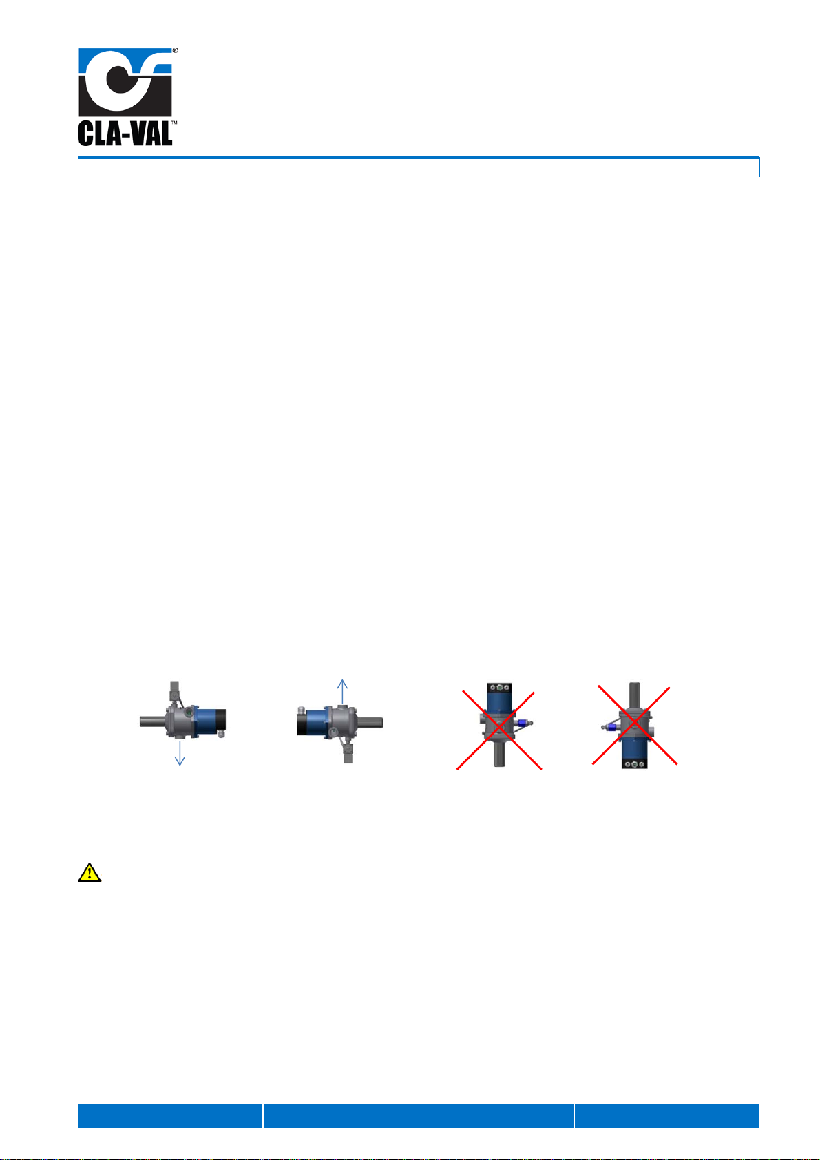
3.1 MOUNTING INSTRUCTIONS
1- The e-Power IP mounting must be horizontal
2- Installation, adjustment and maintenance should be carried out by a competent electrician
3- The electrical connections should be made as described in the user’s manual
4- Before performing any maintenance operation, the main power should be turned off.
: Do not attempt to open the product as this will invalid the warranty!
3.2 QUICK START INSTRUCTION - LIN036ST (SEE ANNEX CHAPTER 7)
Outlet
Sortie
Outlet
Sortie
CLA-VAL e-Power IP
Turbine
Power: 14 W / Voltage: 12 V and 24 V
CLA-VAL Europe www.cla-val.ch [email protected] 11 -LIN036UE - 10/13
© Copyright CLA-VAL Europe - Specifications subject to change without notice - no contractual illustrations.
4 SOFTWARE AND FIRMWARE
4.1 INSTALLATION OF DRIVER USB
Refer to the driver USB installation manual (LIN006UE).
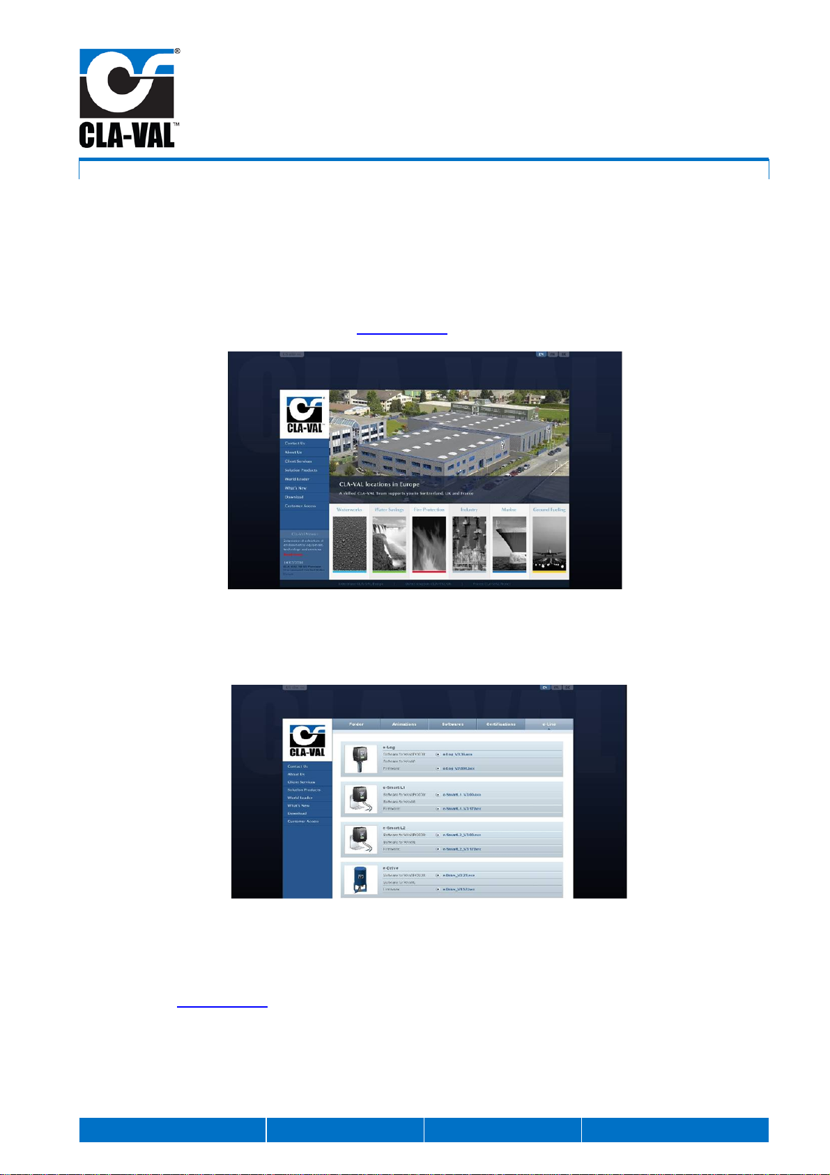
4.2 SOFTWARE / FIRMWARE UPDATE
For Software updates please refer to our web site www.cla-val.ch.
a. Select "Download".
b. Select "e-Line". You will find all the latest Software (PC) & Firmware (Internal Software) updates. Just click on the link
"e-Power IP" to download automatically.
Visit our web site www.cla-val.ch frequently to download the latest updates and news free of charge.

CLA-VAL e-Power IP
Turbine
Power: 14 W / Voltage: 12 V and 24 V
CLA-VAL Europe www.cla-val.ch [email protected] 12 -LIN036UE - 10/13
© Copyright CLA-VAL Europe - Specifications subject to change without notice - no contractual illustrations.
4.3 FIRMWARE UPDATE (INTERNAL SOFTWARE)
1. Connect the e-Power IP battery, wait 1 minute for the cycle « Turbine Check Cycle » to finish.
2. Connect the e-Power IP to the computer with the USB cable.
3. Double click on the e-Power IP icon to start the program.
4. If the connection with the e-Power IP is successful, the e-Power IP appears in the window. Click on the text.
5. Select "Firmware update" in "Parameters", the following window appears :
6. Click "Yes". Open the corresponding file « .hex ».
7. Select "Read Parameters" to check that the Firmware is updated.
4.4 SOFTWARE
All values rated «Default value» are initialized by clicking "Factory Values" and then "Read Parameters".
It is strongly recommended not to change the values « Factory Values » according the table below. Otherwise, the proper
use of the e-Power IP cannot be guaranteed.
When the computer connection cable to the PCB is disconnected, the e-Power IP will initialize. The system reads the
battery voltage. The system goes in charging mode (turbine ON) if the voltage is below 12 V, or in discharging mode (turbine
OFF) if the voltage is greater than 12 V.
Each time you connect the computer to the PCB, please wait until the « Turbine Check Cycle » is complete. Only after
the cycle is complete can you make the connection with the e-Power IP.
4.5 SOFTWARE DESCRIPTION
The description is according to the software picture below.
DESCRIPTION FUNCTION FACTORY VALUE TYPE OF VALUE
Temperature (°C) Electrical box temperature Depends on the environment Automatic
Battery Voltage (V) Battery voltage Depends on the charging state Automatic
Battery Charging Current (mA) Battery charging current Depends on the battery charging
state and the power consumption
on the output voltage 12 V and
24 V (0 mA if the turbine don’t
charge the battery)
Automatic

CLA-VAL e-Power IP
Turbine
Power: 14 W / Voltage: 12 V and 24 V
CLA-VAL Europe www.cla-val.ch [email protected] 13 -LIN036UE - 10/13
© Copyright CLA-VAL Europe - Specifications subject to change without notice - no contractual illustrations.
DESCRIPTION FUNCTION FACTORY VALUE TYPE OF VALUE
Battery Discharging Current (mA) Battery discharging current Depend on the power consumption
on the output voltage 12 V and
24 V (0 mA if the turbine is
charging the battery)
Automatic
Input Power > Output Power (W) Live power consumption of
the battery If green: Battery charging
(power)
If red: Battery discharging
(current )
Automatic
Start turbine @ Low Battery
Level (V) Low level battery
Used to restart the turbine 12.0 V Default value
Start Temporisation @ High
Battery level (V) High battery level is used to
start the temporization. At
the end of the
temporization, the turbine
shuts off automatically
13.0 V Default value
Alarm Battery Level (V) Alarm battery level dry
contact (terminal 3
connections 5 and 6) = 1 if
alarm battery level
11.0 V Default value
Solenoid Pulse
Milliseconds (ms) Pulse duration to switch the
solenoid 99 ms Default value
Forced charge 1 Hour (h) Forced charge (available if
the system is not charging) 05:00 h Default value
Forced charge 2 Hour (h) Forced charge (available if
the system is not charging) 17:00 h Default value
See column « Description » in the
table above
CLA-VAL e-Power IP
Turbine
Power: 14 W / Voltage: 12 V and 24 V
CLA-VAL Europe www.cla-val.ch [email protected] 14 -LIN036UE - 10/13
© Copyright CLA-VAL Europe - Specifications subject to change without notice - no contractual illustrations.
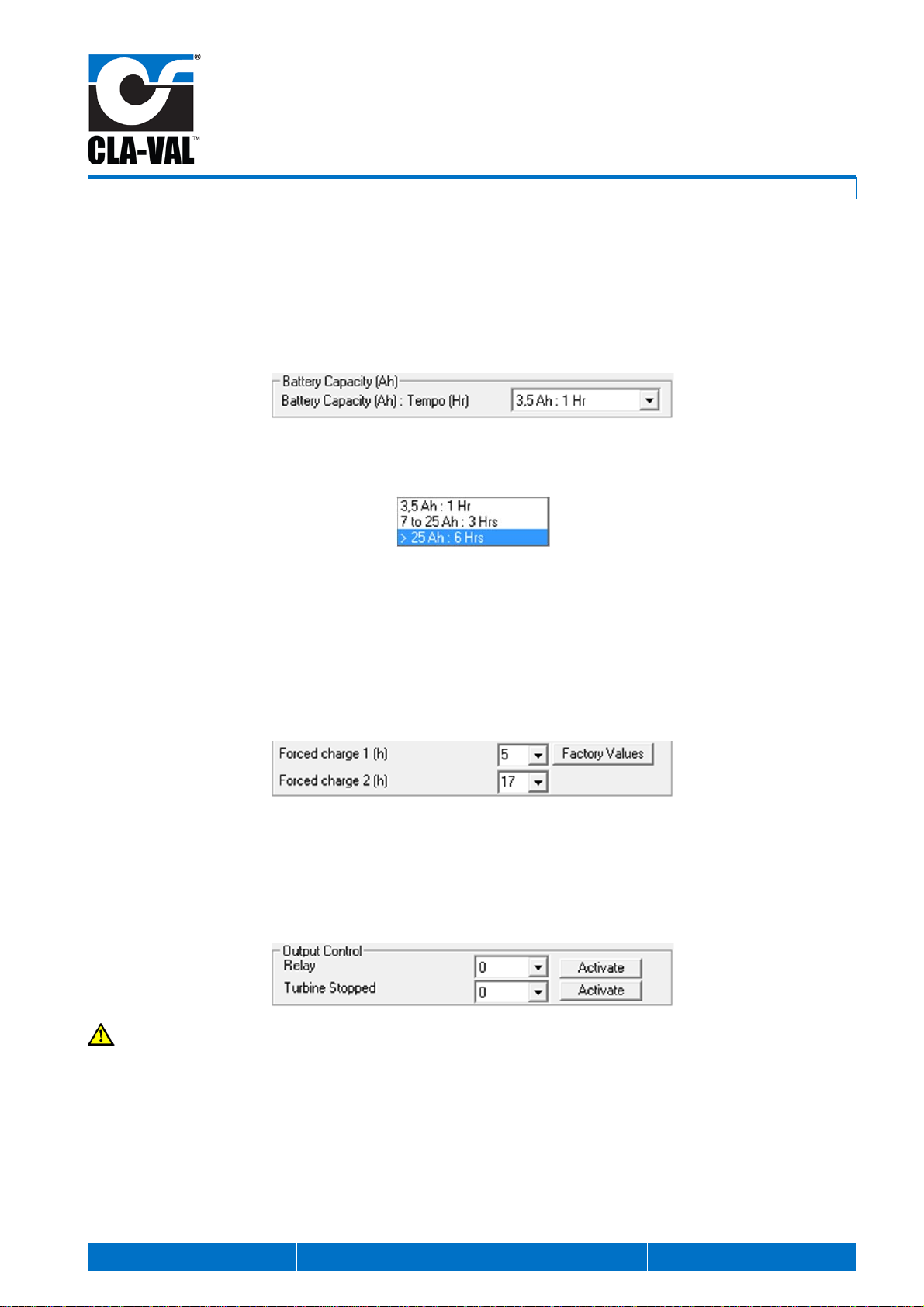
4.6 CHANGING THE BATTERY CAPACITY
To install a new battery for your e-Power IP system, please follow the procedure to change the battery capacity with the help
of the software.
The charging time changes according to the battery capacity.
1. Click on the dropdown menu "Battery Capacity (Ah)".
2. In the dropdown menu, choose according to the battery capacity.
3. Click "Write parameters".
4. The battery capacity change is completed.
4.7 FORCED CHARGE MODIFICATION
The forced charge period can be modified to allow for periods where there is no water or poor differential pressure.
Factory default settings are at 5 AM and 5 PM.
4.8 MANUAL TURBINE OPERATION
Two dropdown window s allow either a ‘0’ or ’1’ command to allow manual switching of the solenoid to start/stop the turbine
and also the « Alarm Battery Level (V) » dry contact.
The dropdown menu « Relay » enables a switch to the dry contact position« Alarm Battery Level (V) ».
The dropdown menu "Turbine Stopped" enables the solenoid to start the turbine (= 1 to activate the turbine).
Do not click "Dynamic reading" while using the manual operations.
CLA-VAL e-Power IP
Turbine
Power: 14 W / Voltage: 12 V and 24 V
CLA-VAL Europe www.cla-val.ch [email protected] 15 -LIN036UE - 10/13
© Copyright CLA-VAL Europe - Specifications subject to change without notice - no contractual illustrations.
5 ASSISTANCE
If you have trouble charging the battery, the battery alarm is active and your electronic device connected to the e-Power IP is
not powered because the battery voltage is too low. Please follow the procedure below:
1. Please follow the procedure « Turbine Check Cycle » (see chapter « How do you check if the e-Power IP runs
properly? » Annex: Quick Start Instruction LIN036ST).
a. If the turbine does not provide enough AC voltage, please follow the point 2 below.
b. If the solenoid does not activate, please contact CLA-VAL.
2. Please follow the procedure of chapter « What is the differential pressure across the turbine » annex: Quick Start
Instruction LIN036ST).
a. If you do not reach 6 meters differential pressure across the turbine (185 VAC), please read on the graph (chapter
« What is the differential pressure across the turbine » Annex: Quick Start Instruction LIN036ST) the real power
provided by the turbine and finally check that your power balance is positive.
b. If the turbine provides no AC voltage, please follow the point 3 below.
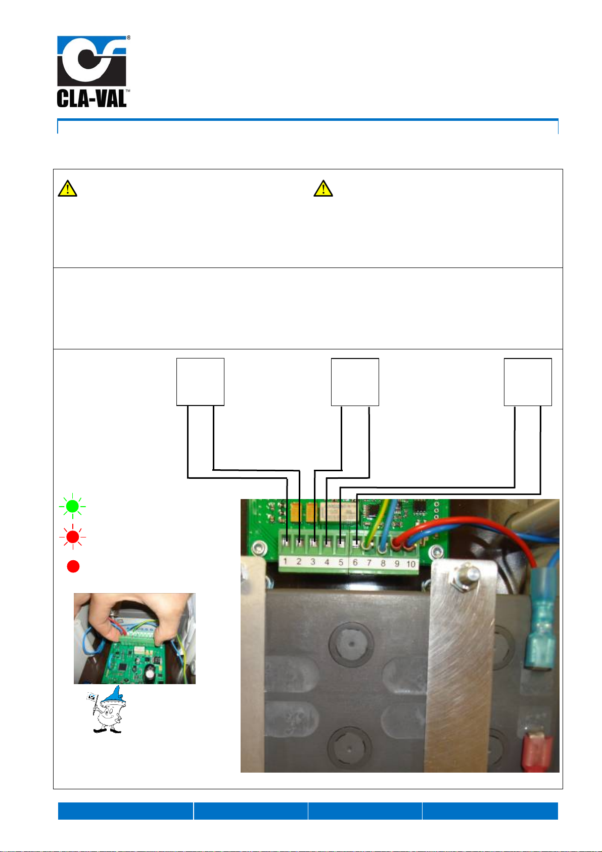
3. Close the bypass ball valve, disconnect the 2 removable terminals at the same time by pulling with 2 fingers (see page
1 of Annex: Quick Start Instruction LIN036ST), With the help of the ohmmeter, measure the resistance of the 3 phases
of 210 ± 10 ohm on the terminal of the PCB (see chapter 2.4 PCB). 3 measurements must be taken: between the cable
pairs: Brown and Black / Brown and Grey / Black and Grey.
a. If you don’t measure 210 ± 10 ohm, the connection between the generator and the PCB is wrong. Contact CLA-
VAL
b. If you measure the good value, proceed to point 4.
4. If during point 1 and 2, the turbine does not provide any voltage, you measure 3 times 210 ohm and you are sure that
the inlet/ outlet ball valves are open, isolate the e-Power IP, purge through the Serto connection of the solenoid on the
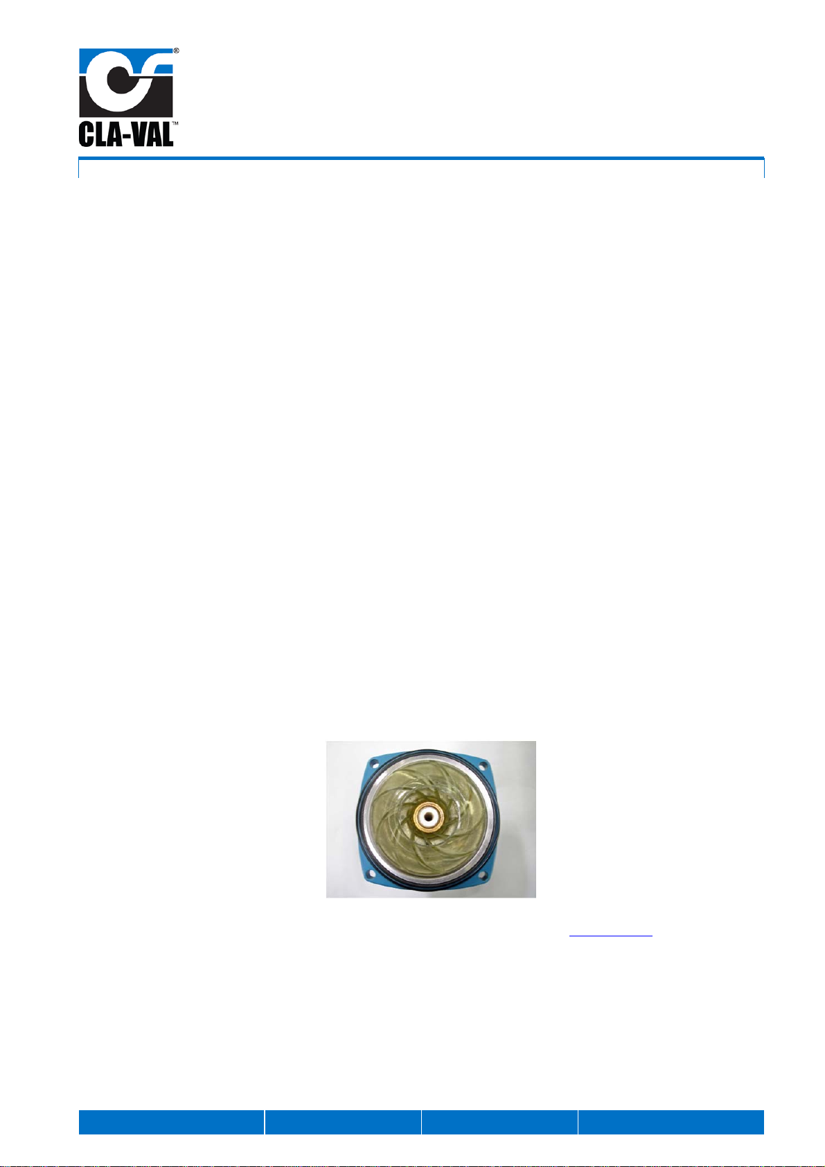
e-Power IP. Unscrew the 4 screws 5 of the generator to the body of the turbine.
When the generator is separated from the body, you have the opportunity to check the turbine wheel as shown on the
picture below. It is possible that the wheel does not rotate, due to the dirt etc. Clean the wheel to be sure that the water
can flow properly through the turbine.
If other troubles occur, please contact the technical support through the internet website: www.cla-val.ch

CLA-VAL e-Power IP
Turbine
Power: 14 W / Voltage: 12 V and 24 V
CLA-VAL Europe www.cla-val.ch [email protected] 16 -LIN036UE - 10/13
© Copyright CLA-VAL Europe - Specifications subject to change without notice - no contractual illustrations.
6 MAINTENANCE
6.1 BATTERY REPLACEMENT
If you use your own lead acid battery 12 V:
Please mount externally if there is not enough space inside the electrical box then use the correct procedure for
connecting the battery to the PCB (see chapter 2.4)
The maximum capacity of the battery is 50 Ah.
1- Ensure that the isolating valve on the bypass is closed.
2- Open the electrical box.
3- Shut down the system by disconnecting the wires connected to the battery.
4- Unscrew the 4 nuts for the fixing of the battery.
5- Replace the battery.
6- Screw the 4 nuts to fix the new battery. ( Don’t screw the battery too tightly; screwing with your hand is enough).
7- Connect the wires from the PCB to the battery. Red wire to the "+"terminal. Blue wire to the "–"terminal. The LED will
start to blink.
8- Wait 1 minute to finish the « Turbine Check Cycle ».
9- If the battery capacity was changed, use the software (see chapter 4.6)..Click "Write Parameters"and wait for 1
minute.
10- Disconnect the battery and reconnect it to check the proper operation of the « Turbine Check Cycle » (see chapter
« How do you check if the e-Power IP runs properly? » Annex: Quick Start Instruction LIN036ST).
e-Power IP commissioned with the
output voltages 12 and 24 V connected

CLA-VAL e-Power IP
Turbine
Power: 14 W / Voltage: 12 V and 24 V
CLA-VAL Europe www.cla-val.ch [email protected] 17 -LIN036UE - 10/13
© Copyright CLA-VAL Europe - Specifications subject to change without notice - no contractual illustrations.
6.1 REPAIR KIT USE
Every 5 years, it is advisable to maintain the e-Power IP with the help of the repair kit *CKEIP-STD-01.
When changing the diaphragm, please pay attention to its orientation during the assembly. The diaphragm is drilled to allow
the water to pass through. Please align the hole drilled in the body, the hole drilled in the cover and the hole in the
diaphragm.
Once the maintenance is complete, please proceed to the « Turbine Check Cycle » (see chapter « How do you
check if the e-Power IP runs properly? » Annex: Quick Start Instruction LIN036ST).
7 ANNEX
7.1 QUICK START INSTRUCTION LIN036ST
29* Filtre
Filter
Filter
21* Joint
Seal
Dichtung
11* Membrane
Diaphragm
Membrane
9* Joint
Seal
Dichtung
30* Joint
Seal
Dichtung
20* Joint
Seal
Dichtung
* CLAKIT = *CKEIP-STD-01
CLA-VAL e-Power IP
Quick Start Instruction / Instruction de montage
CLA-VAL Europe www.cla-val.ch [email protected] 1 -LIN036ST D 07/13
© Copyright CLA-VAL Europe - Specifications subject to change without notice - no contractual illustrations.
Mounting Instructions / Instruction de montage
IMPORTANT SAFETY PRECAUTION!
Before making any wiring connections in the electrical box,
ensure that the isolating valve on the bypass is closed so
that the turbine cannot be engaged. Confirm that the battery
is disconnected. Confirm that the LED on the PCB is not
blinking.
CONSIGNES DE SECURITE IMPORTANTES !
Avant tout raccordement dans le coffret électrique, assurez-
vous que le robinet du by-pass soit fermé pour arrêter la
turbine. L’accumulateur doit être déconnecté. La LED sur
la carte électronique ne doit pas clignoter.
Output voltage 12 VDC: Terminal 1 + 12 VDC and
terminal 2 - 0 V
Output voltage 24 VDC: Terminal 3 + 24 VDC and
terminal 4 - 0 V
Alarm battery (dry contact): Terminal 5 and terminal 6
Sortie de tension 12 VDC: Borne 1 + 12 VDC et borne
2 - 0 V
Sortie de tension 24 VDC: Borne 3 + 24 VDC et borne
4 - 0 V
Alarme batterie (contact sec) : Borne 5 et 6
Tips / Astuces
- Easy connection with the
removable terminal.
-Câblage simplifié à l’aide
du bornier débrochable.
U2U1
12 VDC
Max. 5.0 A
+ 24 VDC
+ 12 VDC
Contact
relais/
Relay
alarm
24 VDC
Max. 2.5 A Max. 250 VAC
Max. 1.0 A
- 0 VDC
- 0 VDC
Green blinking: Turbine OFF
Clignotement vert : Turbine arrêtée
Red blinking: Turbine ON
Clignotement rouge : Turbine en rotation
Red: Default
Rouge : Défaut
Once the electrical connection is complete, connect the
battery:
oRed cable to the terminal +
oBlue cable to the terminal -
Open the isolating valve on the bypass directly after
connecting the battery. The turbine will start to run and
the differential pressure controller will start to regulate.
Check that the LED flashes either red or green. The first
minute is the Turbine Check Cycle where the solenoid
discharges to atmosphere two times (see here below).
Check that the e-Power IP is powering the desired
electronic devices.
Close the electrical box with the 6 screws provides.
The e-Power IP is commissioned and ready to be used.
Une fois le raccord électrique terminé, connectez
l’accumulateur :
oFil rouge à la borne +
oFil bleu à la borne -
Ouvrir le robinet du by-pass directement après avoir
connecté l’accumulateur. La turbine va se mettre à
tourner et le contrôle de différentielle de pression se met
à réguler.
Vérifiez que la LED clignote soit rouge soit vert. La
première minute est le Turbine Check Cycle,
l’électrovanne va donc décharger à l’atmosphère 2 fois
dans le cycle (voir ci-dessous).
Vérifiez que votre équipement électrique soit alimenté.
Fermez le coffret électrique à l’aide des 6 vis.
La e-Power IP est mise en service et prête à l’emploi.
How do you check if the e-Power IP run properly ?
Comment vérifier le bon fonctionnement de la e-Power IP ?
IMPORTANT SAFETY PRECAUTION!
Always connect the battery before opening the isolating
valve on the bypass.
CONSIGNES DE SECURITE IMPORTANTES!
Veuillez toujours connecter l’accumulateur avant d’ouvrir le
robinet du by-pass.
Connect the battery.
Open the isolating valve on the bypass.
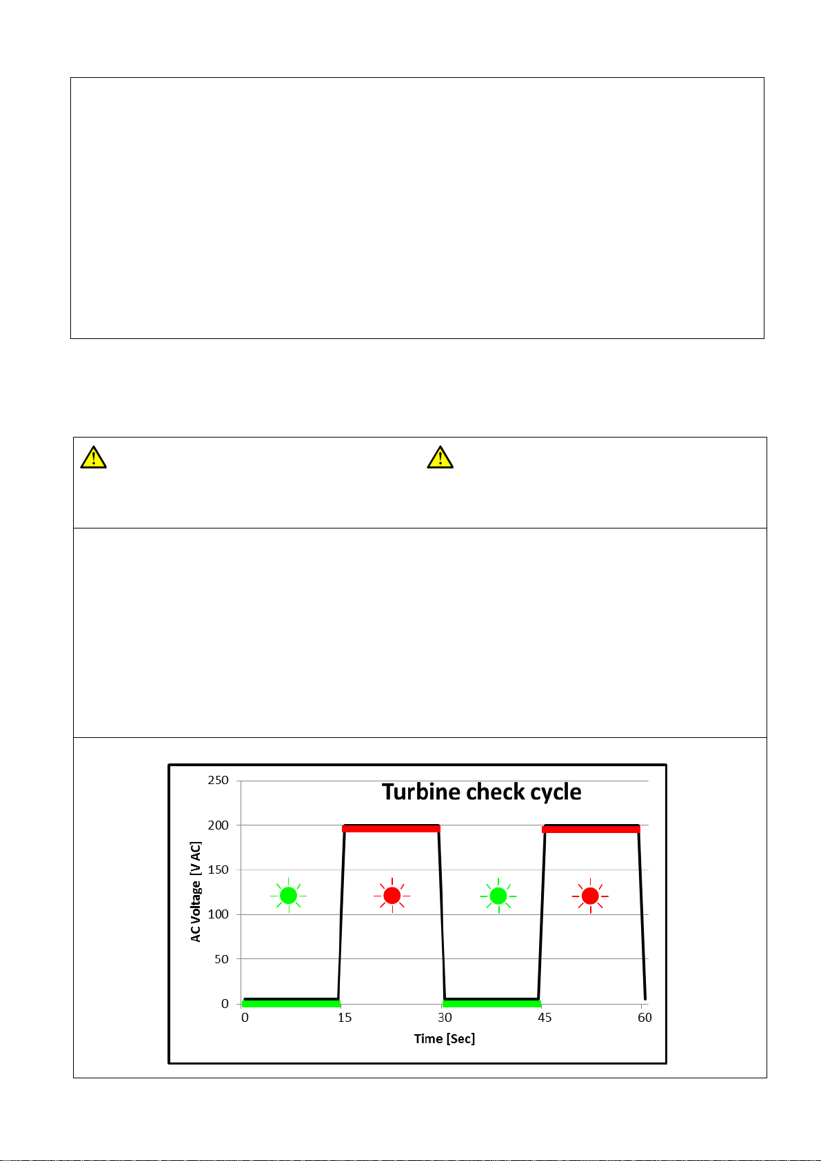
Measure the AC voltage during the Turbine Check Cycle
as illustrated on the next page. The AC voltage depend
on the battery charge level.
At the end of the cycle, the turbine starts or not
depending the battery voltage. Threshold at 12 V.
To reset and restart the Turbine Check Cycle, reconnect
the battery.
Connectez l’accumulateur.
Ouvrez le robinet du by-pass.
Mesurez la tension alternative de la turbine pendant le
Turbine Check Cycle comme illustré à la page suivante.
Suivant la consommation électrique, la tension
alternative peut varier.
Une fois le cycle terminé, suivant la tension de
l’accumulateur, la turbine va démarrer ou non. Transition
à 12 V.
Pour initialiser et redémarrer le Turbine Check Cycle,
reconnectez l’accumulateur.
Turbine OFF
Turbine arrêtée Turbine OFF
Turbine arrêtée
Turbine ON
Turbine en rotation Turbine ON
Turbine en rotation

What is the differential pressure across the turbine / Quelle
est la différentielle de pression à travers la turbine
Close the isolating valve in the bypass to stop the
turbine.
Remove the removable terminal block (Terminal 1 to 10),
referring to diagram at the bottom left side of page 1.
Fermez le robinet du by-pass pour arrêter la turbine.
Débranchez les 2 borniers enfichables (Borne 1 à 10),
voir Astuces page 1.
Remove the solenoid connector using a screwdriver.
Enlevez le connecteur de l’électrovanne à l’aide d’un
tournevis à croix.
Switch the solenoid with a 9 V 6LR61 battery like the
picture to engage the turbine.
Commutez l’électrovanne en présentant la pile 9 V
6LR61 comme ci-dessous pour enclencher la turbine.
Open the isolating valve on the by-pass to engage the
turbine. Ouvrir le robinet du by-pass pour enclencher la turbine.
Measure the AC voltage of the turbine as illustrated on
the next page. Mesurez la tension alternative de la turbine comme
illustré à la page suivante.
Pôle -
Pôle +
WARNING! High AC Voltage
ATTENTION! Tension alternative élevée
Table of contents


