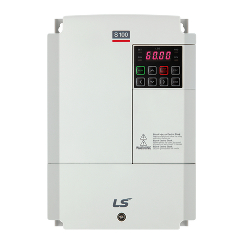
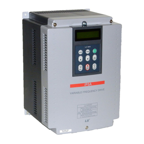
LSIS LSRP-T100LT User manual

LSPV Solar Inverter
User Manual
LSRP-T100LT/T160LT

1
Table of Contents
1 Safety Notes for LSPV Inverter .............................................................................................. 3
1.1 Introduction................................................................................................................. 3
1.2 Explanations ............................................................................................................... 3
1.3 Risks Involved in Improper Use.................................................................................. 4
1.4 General....................................................................................................................... 5
1.5 Protection Against Touching Electrical Parts ............................................................. 6
1.6 Protection against Magnetic or Electromagnetic Fields during Operation and
Assembly .................................................................................................................................... 6
1.7 Protection against Touching Hot Parts....................................................................... 7
1.8 Setting the Country Code ........................................................................................... 7
1.9 Protection when Handling and Assembling................................................................ 8
1.10 Disposal...................................................................................................................... 8
2 General ..................................................................................................................................... 9
2.1 Transport .................................................................................................................... 9
2.2 Storage ....................................................................................................................... 9
2.3 Conditions for Installing ............................................................................................ 10
2.3.1 Environment ............................................................................................................. 10
2.3.2 Ventilation / Cooling.................................................................................................. 10
2.3.3 Tilting the Control Cabinet Roof ............................................................................... 13
2.3.4 Removing the Transport Eyelets .............................................................................. 13
2.3.5 Loosening the Bracket Bolts..................................................................................... 14
2.3.6 Tilting the Roof ......................................................................................................... 14
2.3.7 Tightening the Bracket Bolts .................................................................................... 15
2.4 PV Generator Requirements .................................................................................... 16
2.4.1 DC Connection to the Solar Inverter ........................................................................ 16
2.4.2 Reverse Current Due to Module Defects ................................................................. 16
3 Description of the Unit.......................................................................................................... 17
3.1 Control Terminal Strip Functions.............................................................................. 17
3.2 Monitoring Involving Interruption of Mains Feed-In .................................................. 17
3.3 Block Diagram .......................................................................................................... 18
4 Electricel Connection............................................................................................................ 19
4.1 Warning and Notices ................................................................................................ 19
4.2 Overview of the OPEN Control Cabinet ................................................................... 20
4.3 Line Cross-Sections ................................................................................................. 21
4.4 Power connection ..................................................................................................... 22
4.5 PE Connection.......................................................................................................... 22
4.6 Auxiliary Power Supply............................................................................................. 22
4.7 PV generator ............................................................................................................ 23
4.8 DC-Grounding .......................................................................................................... 23

2
4.9 Control and Communication..................................................................................... 25
4.10 Operator’s Terminal Strip X54.................................................................................. 29
4.11 Operating pad........................................................................................................... 30
4.12 Internal Data Logger................................................................................................. 30
5 Putting into Operation........................................................................................................... 31
5.1 Preconditions............................................................................................................ 31
5.2 Switching On ............................................................................................................ 31
5.3 Setting the Country Code and the Menu Language................................................. 31
5.4 Activating the Device ................................................................................................ 34
5.5 Navigation via the Operating Pad............................................................................. 35
5.6 Menu Structure ......................................................................................................... 38
5.7 ENS Test .................................................................................................................. 46
5.8 Password Entry ........................................................................................................ 47
6 Troubleshooting .................................................................................................................... 48
6.1 Self-test error messages .......................................................................................... 48
6.2 Warnings .................................................................................................................. 48
6.3 Faults........................................................................................................................ 48
6.4 Fault Acknowledgement ........................................................................................... 49
6.5 List of Fault Messages.............................................................................................. 50
7 Maintenance........................................................................................................................... 52
7.1 Maintenance Instructions.......................................................................................... 52
7.2 Maintenance Schedule............................................................................................. 52
8 Technical data........................................................................................................................ 54
9 Contact.................................................................................................................................... 56
10 Certificates ............................................................................................................................. 57

3
1 Safety Notes for LSPV Inverter
1.1 Introduction
To prevent personal injury and/or damages, read the following notes before first putting the system
into operation. The safety notes must be observed at all times.
Before first operation of this unit, we strongly recommend you carefully read through all supplied
documents. This also applies to the safety instructions and all other user instructions before
performing any work on this unit. Should you have no user information regarding the unit, refer to
LSIS. Ask for the documents to be sent immediately to those responsible for safe operation of the
unit.
When selling, letting, or otherwise passing on the device to third parties, always enclose these
safety notes!
WARNING
Any misuse of this equipment, failure to observe these safety notes or
unqualified interference with the safety equipment or unit could result
in damage, bodily injury, electric shock, or even death.
1.2 Explanations
These safety notes use the following ANSI notation to describe the various levels of danger:
Warning
symbol with
signal word
Danger level according to ANSI
The danger level identifies the danger involved in failure to observe the
safety notes:
DANGER
Death or severe bodily injury will occur.
WARNING
Death or severe bodily injury could occur.
CAUTION
Bodily injury or damage could occur.

4
1.3 Risks Involved in Improper Use
DANGER
High electric voltage and high working current! Risk of death or severe
bodily injury by electric shock!
WARNING
High electric voltage because of incorrect connection! Risk of death or
bodily injury by electric shock!
WARNING
Large leakage current!
Make sure to connect to grounding before connecting to the power
supply circuit!
WARNING
Health risk for persons with cardiac pacemakers, metallic implants, or
hearing aids in the immediate vicinity of electrical equipment!
CAUTION
Surfaces of the housing can be hot! Risk of injury! Risk of burns!
CAUTION
Risk of injury by improper handling! Bodily injury by crushing,
shearing, cutting, or striking.

5
1.4 General
•LSIS does not assume any liability for damages caused by failure to observe the warnings
given in these operating instructions.
•Before first operation, thoroughly read through the operation and maintenance instructions and
the safety notes.
•Proper and qualified transport, storage, assembly and installation, as well as conscientious
operation and maintenance are preconditions for faultless and safe operation of this unit.
•Assign trained and qualified personnel to work with electrical systems.
Only suitably trained and qualified personnel should work on this unit. To be qualified,
personnel must be sufficiently familiar with assembly, installation, and operation of the product,
as well as with all warnings and precautions mentioned in these operating instructions.
Furthermore, these qualified personnel must be trained, instructed, or authorized to switch on
and off, and to ground electric circuits and devices according to the safety regulations, and to
mark them appropriately according to the work instructions. Qualified personnel must be in
possession of sufficient safety equipment, and have first aid training.
•Use only accessories and spare parts approved by the manufacturer.
•The safety laws and regulations of the country in which the unit will be used must be observed.
•The ambient conditions specified in the product documentation must be met.
•It is not permitted to put the system into operation until the system in which the products are
installed has been found to conform to the national regulations and the safety regulations for its
application.
•Operation is only admissible if the national EMC regulations for the respective application are
observed.
•The manufacturer of the system or machine is responsible for compliance with the limits
specified by national regulations.
European countries: EC Directive 2004/108/EC (EMC Directive).
•The technical data and conditions for connection and installation are given in the product
documentation, and must be strictly complied with.

6
1.5 Protection Against Touching Electrical Parts
Note: This section only concerns units and unit components that are under
voltages greater than 50 Volts.
It is dangerous to touch parts that are under voltages greater than 50 Volts, since this could result
in electric shock. When electrical equipment is in operation, it cannot be avoided that certain parts
of this equipment will be under dangerous voltage.
WARNING
High voltage! Risk of death or severe bodily injury by electric shock!
⇒LSPV inverter may only be installed by qualified specialists.
Furthermore, the installer must be licensed by responsible power
suppliers.
⇒This unit may only be operated, maintained, and/or repaired by
personnel trained or qualified for working on or with electrical
equipment.
⇒Observe the general construction and safety regulations for working
with heavy-current installations.
⇒Before switching on, it must be checked that the power plug is firmly
(locked) in place.
⇒The PV generator may only be connected when it is completely de-
energized.
⇒The operator must observe all of the above regulations at all times.
WARNING
Photovoltaic systems have certain special characteristics that present
additional dangers!
⇒A live power source is connected. The inverter could therefore be under
high voltage from the PV generator, depending on operating status.
⇒Live strings can be under lethal DC voltages.
⇒When disconnecting systems, these high voltages can lead to electric
arcs if there is a fault or if fuses are used improperly.
⇒An TN-C/TN-S network system (isolated star point) is required for
connecting the central inverter.
1.6 Protection against Magnetic or Electromagnetic Fields
during Operation and Assembly

7
Magnetic and electromagnetic fields exist in the immediate vicinity of power-carrying conductors
and can be a serious danger to people with cardiac pacemakers, metallic implants, or hearing aids.
WARNING
Health risk for persons with cardiac pacemakers, metallic implants, or
hearing aids in the immediate vicinity of electrical equipment!
⇒People with cardiac pacemakers and metallic implants are forbidden to
access the following areas:
Areas in which electrical equipment and parts are assembled,
operated, or set up.
⇒If a cardiac pacemaker patient must access these areas, a physician
must be consulted beforehand. The interference immunity of present or
future implanted cardiac pacemakers differs greatly, so that no general
rules can be given.
⇒People with metal implants or metal fragments, or persons wearing
hearing aids must consult their physicians before accessing such areas,
as a risk to their health must be assumed.
1.7 Protection against Touching Hot Parts
CAUTION
Surfaces of the housing can be hot! Risk of injury! Risk of burns!
⇒Do not touch parts of the housing that are close to heat sources! Risk of
burns!
⇒Before accessing a unit, leave it to cool for 15 minutes after switching off.
1.8 Setting the Country Code
CAUTION
The selected country code can only be changed by Service personnel!
After having set and confirmed the country code, you cannot change it yourself
any longer.
This is also applicable to devices which are or were in operation. According to
a new rule, the country code can now only be changed by Service personnel.
CAUTION
Cancellation of the operating license!
If the LSPV inverter is operated with a wrong country code, the electric supply
company may cancel the operating license.

8
Note: We do not assume any liability for an incorrectly set country code!
The pertinent regulations of the responsible power supplier must be
observed!
1.9 Protection when Handling and Assembling
In unfavorable conditions, handling and assembling certain parts and components in an improper
way can cause injuries.
CAUTION
Risk of injury by improper handling! Bodily injury by crushing, shearing,
cutting, striking or lifting!
⇒Observe the general construction and safety regulations on handling and
assembly.
⇒The weight of the LSPV inverter is 860 kg!
⇒Use suitable assembly and transport equipment.
⇒Take appropriate measures to prevent jamming and crushing.
⇒Only ever use suitable tools. Use special tools if specified.
⇒Use lifting equipment and tools in the correct manner.
⇒If necessary, use suitable protective equipment (for example safety
goggles, safety shoes, safety gloves).
⇒Do not stand under suspended loads.
⇒Immediately clean up any spilled liquids to avert the danger of skidding.
1.10 Disposal
Note: RoHS-compliant components are used wherever possible in the LSPV
inverter. It is recommended to dispose of the unit through a specialized
waste management facility.

9
2 General
You have made a good choice in purchasing a LSPV inverter. In order to guarantee reliable
operation, all connections must be made correctly. The information you will need for this is given in
the following chapters and in the safety notes.
Figure 1: View of the LSPV inverter control cabinet
2.1 Transport
The LSPV inverter consists of a control cabinet in which all components required for its operation
are housed. The control cabinet has 4 transport eyelets attached to the roof. Given the
considerable weight of the LSPV inverter ®, it is recommended to use a crane to load and unload it
when transporting.
2.2 Storage
Store in a dry place protected against moisture ingress.

10
2.3 Conditions for Installing
Note: Failure to observe the below conditions might render the warranty invalid.
2.3.1 Environment
oThe floor beneath the cabinet must be strong enough to bear the great weight. For weights,
see technical data.
oAdherence to the minimum passage widths when installing in electrical operation rooms.
See DIN VDE 0100 Parts 729 and 731.
oEMC and noise level (take necessary measures as needed).
2.3.2 Ventilation / Cooling
The LSPV inverter is cooled by four fans: two in each cabinet door. To ensure sufficient cooling,
the below conditions must be met:
oWhen delivered in IP21, the cabinet roof of the LSPV inverter must be tilted before
commissioning. This is essential since otherwise no sufficient cooling of the components in
the control cabinet can be guaranteed.
oAdherence to permitted ambient temperatures by suitable ventilation. For cooling, the unit
requires an air flow rate of 2500m³ air / hour (maximum capacity at the output).
oThe supplied air must not contain any aggressive or electrically conductive gases or gases
that jeopardize system function.
oThe doors must be closed during operation.
oThe supplied air must be dust-free! In order to protect the interior space of the inverter
against contamination, filter mats are installed in front of the door fans, which must be
replaced more or less frequently depending on the cleanliness of the supplied air. Unless
the filter mats are replaced periodically, they will clog, which might cause overtemperature
shutdowns and thus interruptions in operation.
oIt is recommended to draw in the air from the north (coldest air), but not at any case from
the south or west.
oIn accordance with the environmental classification 3K3, moisture condensation or icing
must not occur. The relative humidity must range from 5% to 85%.
If the above conditions do not need to be met, please observe the below installation advice:

11
IP24 Housing
Filter mat
1500
min. 1000 max.
200
Air duct
Filter mat
Filter mat

12
Abutting Installation
REFUSOL REFUSOL
Air duct
Spaced Installation
REFUSOL REFUSOL
Air duct Air duct

13
2.3.3 Tilting the Control Cabinet Roof
In order to guarantee sufficient cooling of the control cabinet components, the roof of the cabinet
must be tilted before the system is put into operation. To do this, proceed as follows:
2.3.4 Removing the Transport Eyelets
First remove the four transport eyelets on the control cabinet roof.
Figure 2: Transport eyelets, left
Figure 3: Transport eyelets, right

14
2.3.5 Loosening the Bracket Bolts
Open the control cabinet doors and loosen the fastening bolts on the roof brackets at the top of the
cabinet frame.
Figure 4: Right bracket bolts, roof folded down
Figure 5: Left bracket bolts, roof folded down
2.3.6 Tilting the Roof
After having loosened the roof bracket fastening bolts, tilt the roof (see figure 6)!
Figure 6: Tilted roof

15
2.3.7 Tightening the Bracket Bolts
Now tighten the bracket bolts firmly
Figure 7: Right bracket bolts, roof tilted up
Figure 8: Left bracket bolts, roof tilted up
CAUTION
Risk of injury!
Secure the roof against falling down again!

16
2.4 PV Generator Requirements
2.4.1 DC Connection to the Solar Inverter
The PV generator must not exceed the following operational characteristics under any
circumstances!
Max. DC voltage 850 V
Max. DC current 240 A
2.4.2 Reverse Current Due to Module Defects
Reverse currents are fault currents that only occur in PV systems comprising strings in parallel.
Given short circuits of individual modules or cells in a module, or a double ground fault, the open
circuit voltage of the string in question can drop (e.g. due to defect modules or parts of modules) so
far that the intact strings connected in parallel will drive a reverse current through the defect string.
In the worst case, this can destroy the string.
The reverse current can also cause secondary damage.
In order to prevent such damage to PV systems, appropriate measures should be taken. There are
two different cases:
1. The PV system is designed in a way that the reverse current flowing in an event of fault,
which in the worst case consists of the sum of the short-circuit currents of all intact
strings, does not lead either to the destruction of the damaged string or to any secondary
damage. This depends on the current-carrying capacity of the system components
(connectors, lines) and the reverse current resistance of the modules. These can be
seen from the manufacturer’s data sheet! In this case, no further measures are
necessary.
2. The PV system is designed in a way that the reverse current occurring in an event of
fault exceeds the destruction limit. In this case, each string must individually be
protected by a serially connected string fuse. In the event of fault, the string will then be
isolated from the intact strings, thus preventing their destruction.

17
3 Description of the Unit
The LSPV inverter consists of a control cabinet in which all components required for function and
safety are installed. That means the only work required for installation is to connect the mains
feeder, the auxiliary power and the PV generator.
The following section describes the components of the AC inverter and DC part contained in the
cabinet.
The AC part contains a 4-pin circuit breaker that trips upon thermal overcurrent or short-circuit. This
circuit breaker can be manually tripped by an operator from outside the closed cabinet. Remote
disconnection is possible through an external floating contact. The AC part also houses the mains-
side surge protector, the EMC filter, mains disconnection contactor, and galvanic isolation in the
form of a 3-phase AC isolation transformer.
The inverter consists of a modular power circuit and a control unit.
The DC part contains the precharge circuit and two motor-driven DC isolating switches for the DC
positive and DC negative lines. This is triggered upon thermal overcurrent or short-circuit. Two
indicator lamps in the cabinet door indicate when the PV generator is connected and the inverter is
feeding into the mains. The DC positive and negative line are internally connected to PE over an
isolation measuring unit, which triggers a fault in the case of a DC-side ground connection.
The graphic display built into the cabinet door, with an 8-key control pad, lets you display various
data such as feed-in curves, giving you outstanding ease of operation and navigation.
3.1 Control Terminal Strip Functions
The following control terminal strip functions are provided for the operator's use. The control
terminal strip assignment is shown in the connection diagram.
oRemote stop circuit breaker / mains disconnection
oFeedback contact for mains circuit breaker
oOperator enabling of solar generator connection
oOperator enabling of mains feed-in
o"Fault" feedback
oFault acknowledgement
3.2 Monitoring Involving Interruption of Mains Feed-In
If any of the following faults occur, then the fault must be acknowledged as described in Chapter
6.3.1
oSystem voltage not OK
oUnder/overvoltage
oUnder/overfrequency
oIsland formation
oDC voltage too high
oCooler temperature too high
oFault in power circuit inverter
oGround fault in PV generator

18
3.3 Block Diagram
Figure 9: Block diagram of LSPV inverter ®
1) Circuit-breaker (-Q10)
2) Lightning protection (-F10)
3) EMV – mains filter (-V10)
4) Supply disconnection contactor (-Q11)
5) Three-phase transformer (-T10)
6) Inverter (-T20)
7) Contactor (-Q22)
8) Contactor (-Q23)
9) Overload protection (-F20)
10) EMV – DC-Filter (-V20)
11) Circuit-breaker with motordrive (-Q20)
12) Inverter controller (-T20)
13) DC – Voltage metering
14) Insulation measuring (-A21)
15) Auxiliary supply
16) Overvoltage protection (-F15)

19
4 Electricel Connection
4.1 Warning and Notices
DANGER
Fatal electric shock from live parts under more than 50 V!
⇒LSPV inverter units operate at high voltages. They may only be worked on
when completely de-energized!
⇒They may only be worked on by qualified personnel!
⇒Failure to observe this safety warning can lead to death, severe bodily injury
or considerable damages.
⇒The DC bus capacitors remain under dangerously high voltage even when
the power has been disconnected.
They take more than 5 minutes to discharge!
Accordingly, it is only permitted to work on the unit or DC bus terminals after
the appropriate waiting period, and only when it has been verified that the
system is completely de-energized.
⇒When working on the open unit, keep in mind that some parts are still live.
⇒The operator is responsible for all units to be installed and connected in
accordance with the recognized technical regulations of the country it is
installed in, and other regional regulations. Cable dimensions, fuses,
grounding, shutdown, isolation and overload protection must be given
special attention.
CAUTION
Damage to units because of incorrect connection!
Strictly observe the type plate and the mains power rating specified in the
technical data when connecting.
CAUTION
Damage to the unit due to excessive DC current!
The DC current must never exceed 240 A under any circumstances,
otherwise the unit could be severely damaged.
This manual suits for next models
1
Table of contents
Other LSIS Inverter manuals

LSIS
LSIS H100 Programming manual

LSIS
LSIS iG5H Series User manual

LSIS
LSIS SV-iS7 series User manual

LSIS
LSIS LSPV Series User manual

LSIS
LSIS LSLV-S100 Series User manual

LSIS
LSIS SV110IP5A-4NE User manual

LSIS
LSIS LSLV0055H100-4COFN User manual

LSIS
LSIS iS7 PROFInet User manual

LSIS
LSIS SV-iS7 series User manual

LSIS
LSIS SV-iV5 Series User manual
Popular Inverter manuals by other brands

SycoTec
SycoTec easyDrive TV 4504 Short instructions for use

GE
GE HOME NERATOR SYSTEM 18000 WATT Installation and start-up manual

Kisae
Kisae IC1220100 Owners manual/install guide

Denver
Denver BSS-10610 user guide

Lust
Lust CDA3000-PLC System manual

Solectria Renewables
Solectria Renewables PVI 13KW Installation and operation manual