Claas Mercedes-Benz OM906LA Operating instructions

Service & Parts
Mercedes-Benz OM906LA
Mercedes-Benz OM926LA
Repair manual

1044-004

Table of contents
Introduction
General Information................................................................................................................................. 4
General repair instructions..................................................................................................................... 8
Torque settings........................................................................................................................................ 20
CCN explanation
CCN (CLAAS Component Number)........................................................................................................ 32
CCN (CLAAS Component Number)
Safety
General Information................................................................................................................................. 36
01 Engine
0102 Complete component..................................................................................................................... 48
0105 Engine suspension......................................................................................................................... 59
0110 Engine housing............................................................................................................................... 61
0115 Engine unit...................................................................................................................................... 81
0120 Cylinder head / Valves / Idler gear................................................................................................ 117
0125 Injection - / Fuel system................................................................................................................. 152
0130 Lubricating oil system.................................................................................................................... 176
0135 Cooling system............................................................................................................................... 196
0140 Exhaust system.............................................................................................................................. 212
0145 Air intake......................................................................................................................................... 231
0150 Engine attachment parts................................................................................................................ 234
0155 Engine control................................................................................................................................. 255
0165 Exhaust gas treatment................................................................................................................... 257
Index.................................................................................................................................... 284
1044-004
00 0296 433 2 - RHB Dieselmotor OM906/926LA - 10/2014 3

Introduction
General Information
162113-001
Validity of manual
This manual applies to the Mercedes-Benz diesel
engines below:
Engine Type design Engine no.
OM 906 LA 906.991 906.991-00-xxxxxx
OM 926 LA 926.929 926.929-00-xxxxxx
OM 926 LA 926.959 926.959-00-xxxxxx
OM 926 LA 926.970 926.970-xx-xxxxxx
123139-005
Handling the manual
This repair manual should help you to maintain
ongoing operational capacity. The high value of the
harvesting machine is ensured through careful
maintenance and technical monitoring by customer
service.
This repair manual is a compilation of our service
technicians' and shop-floor experience.
The picture sequence demonstrates the steps in a
repair procedure. The text provides you with the
information required for making adjustments, using
special tools and further similar information.
Essential repairs are listed in such a way that even
individual and small repairs can be easily found and
followed.
Supplements are added to reflect the ongoing
technical development of the machines and the
manual is thereby continuously being updated as a
reference book.
As a precaution, always compare the setting values
and fill quantities with the most recent operator's
manual and the technical systems documents for the
respective machine.
Texts and figures
Pictures and graphics apply to all models covered by
this manual. Differences are highlighted by captions
below the figures.
In general, texts are short and apply to all models
covered by this manual. Differences are highlighted by
intermediate headings.
Different text categories can be easily identified by the
formatting. The following different formattings are
distinguished:
Introduction
General Information
1044-004
4 00 0296 433 2 - RHB Dieselmotor OM906/926LA - 10/2014

Formatting Meaning Description
Description Descriptive text Further information on the subject.
–Procedure
instructions
Process Operations which must be carried out one after the
other.
Result Result Result of the processes carried out.
References can be easily identified by corresponding
symbols. The following symbols are distinguished:
Symbol Meaning Description
See index The symbol indicates that further information on
this subject is available in other sections of this
manual.
See the index of the
Operator's Manual in
question
The symbol indicates that further information on
this subject is available in the Operator's Manual of
the machine or of the implement in question.
Document structure based on the assembly
structure
The chapters of the present manual are subdivided
into assemblies as far as contents permit. The
structure of these assemblies is the same in all
chapters.
Different product groups have different assembly
structures. CLAAS makes every effort to keep this
assembly structures identical in any document.
Search and find
Due to the constantly recurring assembly structure,
the subject in question can be quickly found using the
table of contents or the header of this manual.
In addition, the index provided in this manual is a
useful tool for locating a subject. The index can be
found on the last pages of this manual.
Directions
Front, rear, right and left refer to the direction of
forward travel. If necessary, a direction arrow is used
for indicating the direction of travel in figures.
Introduction
General Information
1044-004
00 0296 433 2 - RHB Dieselmotor OM906/926LA - 10/2014 5

Abbreviations
Abbreviation Description
bar bar (unit for pressure)
approx. approximately
cm Centimetre
DIN German Standardization Institute
EC European Community
EN European Standard
GPS Satellite navigation system
h Hours
Ident no. Identification number of machine
ISO International Standardization Organisation
kg Kilogram
kPa Kilopascal
km Kilometre
km/h Kilometres per hour
m Metre
mm Millimetre
Nm Newtonmetre
psi pound per square inch
StVZO German Regulations Authorizing the Use of Vehicles for Road Traffic
e.g. for instance
% percent
°C degrees Celsius (unit for temperature)
Introduction
General Information
1044-004
6 00 0296 433 2 - RHB Dieselmotor OM906/926LA - 10/2014

Technical terms
Technical term Description
recycle Re-use of used, defective or no longer required products
Season Recurring periods of a year
Ignition TDC Ignition top dead centre (diesel engine piston position)
Overlap TDC Valve overlap top dead centre (diesel engine piston position)
BDC Bottom dead centre (diesel engine piston position)
Your CLAAS Service Department
Introduction
General Information
1044-004
00 0296 433 2 - RHB Dieselmotor OM906/926LA - 10/2014 7

General repair instructions
123153-002
Technical specifications
Technical specifications, dimensions and weights are
non-binding. Technical specifications are subject to
modification in the course of technical development,
and all errors and omissions are excepted.
123192-003
Information on proper repairs
►Mark rotating machine components before
removing or dismounting them in order to ensure
well-balanced component seating on the correct
side after refitting.
►The slots of expansion pins must always point to
the loaded side.
When they are installed with a 90° twist, they
come loose, fall out or shear off.
►Replace cotter pins, locking wires, sheet retention
devices, lock washers and spring washers in the
repair process.
►Align sprockets and V-belt pulleys with one
another.
►Observe the information in the hydraulic system
chapter when working on the hydraulic system.
►Do not mix different oil grades.
123164-004
Self-locking bolts
Self-locking bolts must not come in contact with
sealing compound.
►Tighten self-locking bolt speedily up to the
specified torque.
► The full hardening time can be reduced by
heating-up, e.g. to 15 minutes at + 70 °C.
► The full load capacity is achieved after
24 hours at + 20 °C.
►When unscrewing self-locking bolts, unscrew
them quickly.
120820-003
Liquid locking compound
►Use liquid locking compound (glue) only at the
spots described in the Repair Manual.
►The surfaces to be joined must be absolutely
clean and free of grease.
► A suitable cleaner and an activator possibly
delivered along with the glue can be used for
cleaning.
►No cleaner residues may remain on the surfaces
to be joined.
This applies in particular to tapped holes with a
bottom.
► Let the surfaces dry well before applying the
glue.
1
151599-001
Introduction
General repair instructions
1044-004
8 00 0296 433 2 - RHB Dieselmotor OM906/926LA - 10/2014

►Apply the glue only in the areas shown in the
figure if possible.
When applying the glue at an unfavourable spot
or when applying too much glue, the joint may
tear off when loosening.
►Observe the glue producer's instructions for use
and application!
A joint secured by liquid locking compound can be
loosened by heating up to approx. 200 °C.
120771-004
Steel roller chains
Tensioning
Checking the tension of steel roller chains:
►Apply a small load to the tight span.
►Push down the slack span in the middle between
the sprockets with your thumb.
You should be able to push down the slack span
around 2 % of the spacing between the axles.
Example:
Axle spacing (A) = 500 mm
Pushing distance (x) of slack span = approx. 10 mm
Chain connector
►The closed side of chain connector (1) must point
in running direction (L)!
A
x
2
13827-006
1
3
123668-001
Introduction
General repair instructions
1044-004
00 0296 433 2 - RHB Dieselmotor OM906/926LA - 10/2014 9
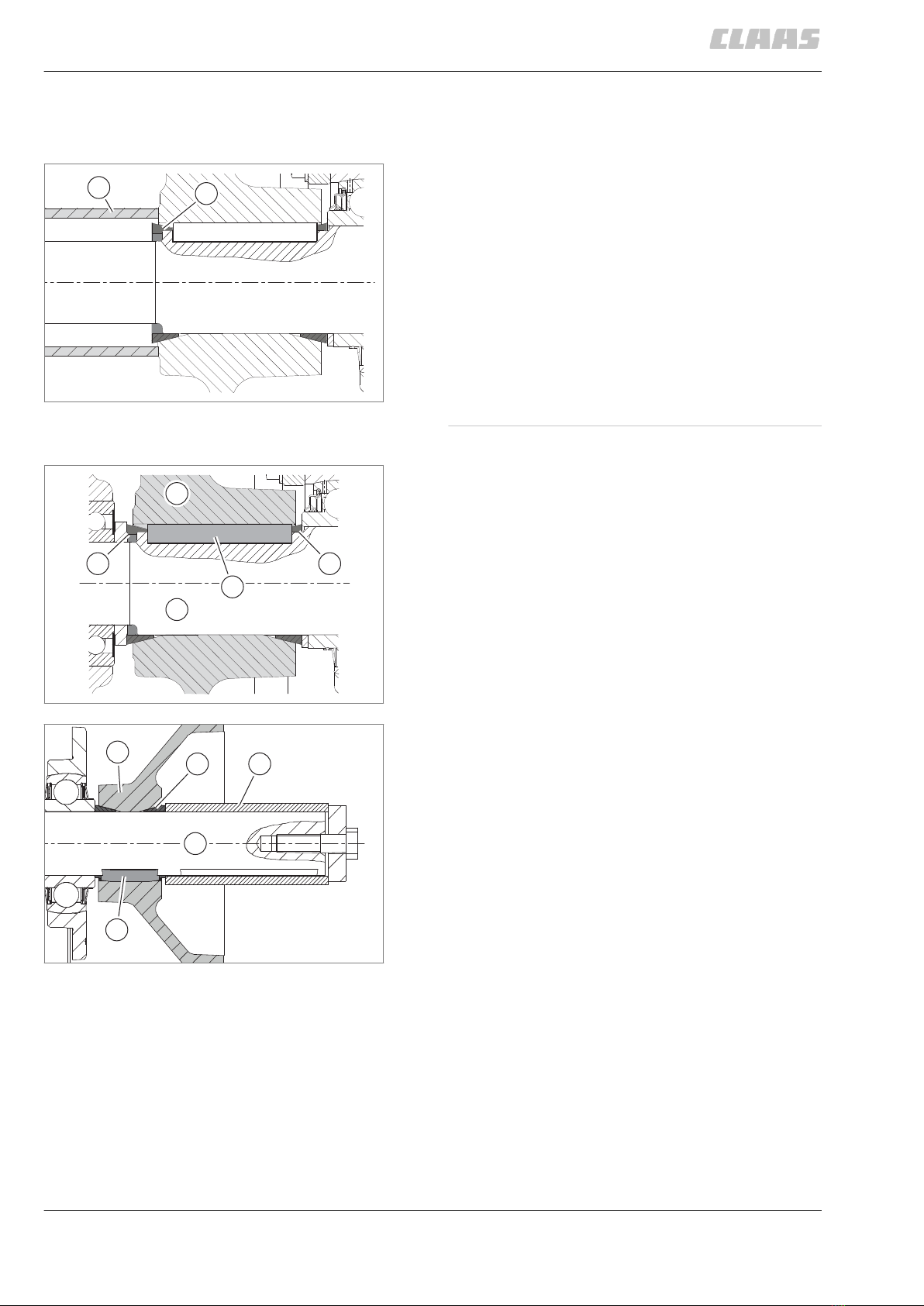
120801-005
Taper ring fasteners
Dismounting
►Slacken off tapered ring (1) with a blow.
► Use an auxiliary tool (2) if required.
Installation
13975-003
NOTICE! Sticking together at the taper ring fasteners.
The joint cannot be loosened or comes off only with
difficulty.
► Do not install parts with tough grease.
►Clean shaft (1), hub (2), parallel key (3) and
tapered rings (4) thoroughly and apply some
CLAAS AGRIGREASE LC 00 / 000.
►Tighten to the specified torque.
► In case of several taper ring fasteners fitted
behind one another, tighten those
separately.
► Use an auxiliary tool (5) if required.
1
2
4
154769-001
4
3
2
1
4
5
154486-001
5
4
3
2
1
6
154768-001
Introduction
General repair instructions
1044-004
10 00 0296 433 2 - RHB Dieselmotor OM906/926LA - 10/2014

123163-004
Gib head key joints
Dismounting
►Slacken off gib head key (1) with a blow if
possible.
► Use an auxiliary tool (2) if required.
►Drive out the gib head key (2) with a key
drawer (1).
► Ensure that the key drawer is used as shown
in the figure.
Installation
The gib head key (1) comes in raw condition as a
spare part and must be machined to suit the
application by milling or grinding.
2
1
7
154811-001
2
1
8
154813-001
2
1
9
154812-001
Introduction
General repair instructions
1044-004
00 0296 433 2 - RHB Dieselmotor OM906/926LA - 10/2014 11
►Grind the gib head key (1) to suit the application
at surface (2).
► Surface (3) must not be machined.
►Clean shaft, hub and keyway to be free of grease,
paint and rust prior to assembly.
85675-003
NOTICE! Excessive force employed when installing
the gib head key. Damage to the gib head key joint.
The gib head key cannot be removed any more.
► Drive in the gib head key carefully with a suitable
and not too heavy hammer.
►Ensure that the gib head key is driven in only so
far that it can still be removed without problems,
using a key extractor.
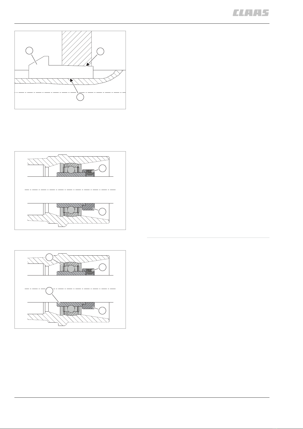
123167-002
Lock collar bearing
Dismounting
►Slacken off set screw (1).
►Drive off eccentric ring (2) against the shaft's
sense of rotation.
►Remove bearing.
Installation
►Tighten lock collar bearing (1) on the shaft by
twisting eccentric ring (2) over the inner bearing
race (3).
► Arrest the eccentric ring with moderate force
in the sense of rotation of the shaft.
► To make dismounting easier, the inner race
and the shaft can be coated with
CLAAS AGRIGREASE LC 00 / 000.
►Tighten set screw (4).
2
13
10
154492-001
1
2
11
154814-001
4
3
2
1
12
154500-001
Introduction
General repair instructions
1044-004
12 00 0296 433 2 - RHB Dieselmotor OM906/926LA - 10/2014
120831-003
Adapter sleeve bearings
Dismounting
►Loosen the tab of sleeve nut (3).
►Slacken off sleeve nut by some turns only.
► Ensure that the thread is still completely
engaged.
►Slacken off expansion pin (2) with a firm blow.
►Pull off adapter sleeve bearing (1) completely.
Installation
►Clean expansion pin (2) and shaft and check easy
movement of the sleeve nut (3).
►Install adapter sleeve bearing (1) according to the
conical inside ring (2).
►Tighten the sleeve nut with the suitable special
tool and to the prescribed torque.
►Continue tightening the sleeve nut to the specified
degrees.
►Tighten sleeve nut until the nearest tab can be
applied.
►Secure sleeve nut with the tab.
144598-002
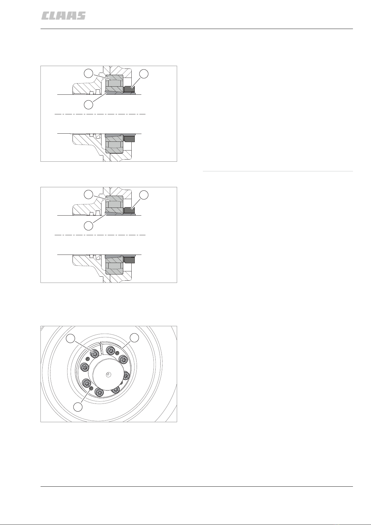
Chuck bushing
Dismounting
►Unscrew bolts (1).
►Screw in bolts (1), or longer bolts if required at (2).
► Screw in bolts until the chuck bushing (3)
comes loose.
► Apply a little oil to bushing if necessary.
►Remove the chuck bushing if required.
3
2
1
13
154510-001
3
2
1
14
154510-001
3
1
2
15
Version 1 154820-002
Introduction
General repair instructions
1044-004
00 0296 433 2 - RHB Dieselmotor OM906/926LA - 10/2014 13

Installation
►Clean chuck bushing (1) and shaft thoroughly.
►Insert chuck bushing.
► Ensure that slots (3) and (4) are mounted
with the maximum possible angle offset.
►Tighten bolts (2) evenly crosswise in three steps.
► Observe the specified torques of the
respective steps.
3
1
1
16
Version 2 154836-002
1
2
3
4
max. 180°
17
Version 1 185680-001
1
2
18
Version 2 154844-002
Introduction
General repair instructions
1044-004
14 00 0296 433 2 - RHB Dieselmotor OM906/926LA - 10/2014

144716-004
Circlips
144718-002
NOTICE
Overspreading the circlip.
Plastic material deformation.
No safe fixing of component.
► Spread circlip only as far as needed for
installation and dismounting.
► Do not use any circlip already overspread before.
►Insert circlips as shown in the figures.
► Ensure that chamfer (1) does not make
contact with the component to be secured.
► If required, make circlip engage with a slight
blow.
1
19
Circlip DIN 471 155144-001
1
20
Circlip DIN 472 155145-001
Introduction
General repair instructions
1044-004
00 0296 433 2 - RHB Dieselmotor OM906/926LA - 10/2014 15

120840-004
Ferrule fittings
Screwing in
►Cut off the corresponding tube at right angles.
► Do not use a pipe cutter.
In case of pipe bends, the straight pipe end up to
where the bending radius starts must be at least
twice the height of the union nut.
►Slightly deburr the pipe end on the inside and
outside.
► Do not chamfer the pipe end.
►Clean the pipe end.
►Push the union nut (1) and the ferrule (2) on the
pipe.
►Push the pipe against the stop in the connector
(3) and tighten the union nut until the ferrule
seizes the pipe.
This pressure point can be felt because increased
power is needed from here.
The pipe must be fixed securely during assembly
and must not rotate.
►Tighten the union nut by half a rotation beyond
the first pressure point.
►Check the incision at the cutting edge.
A visible collar must fill the space ahead of the
ferrule face end.
The ferrule may rotate, but axial displacement
must not be possible.
►Insert the pre-assembled pipe into the well-oiled
threaded joint.
►Screw on the union nut until the power needed to
do this clearly increases.
►After that, continue to screw the union nut on for
half a turn beyond that point.
► Observe the tightening torques. Page
23
Non-tight ferrule connection
►If a connection leaks, loosen the union nut until
some oil escapes.
►Then tighten according to instructions.
►Replace the seal (4) if required.
3
2
1
21
Ferrule without seal 154515-001
43
2
1
22
Ferrule with seal 154516-001
Introduction
General repair instructions
1044-004
16 00 0296 433 2 - RHB Dieselmotor OM906/926LA - 10/2014

123189-002
Sealing cone fittings
►Apply seal (1) on the sealing cone (2).
►Tighten the union nut (3) a third of a turn beyond
the point where resistance is felt.
► Observe the tightening torques! Page
24
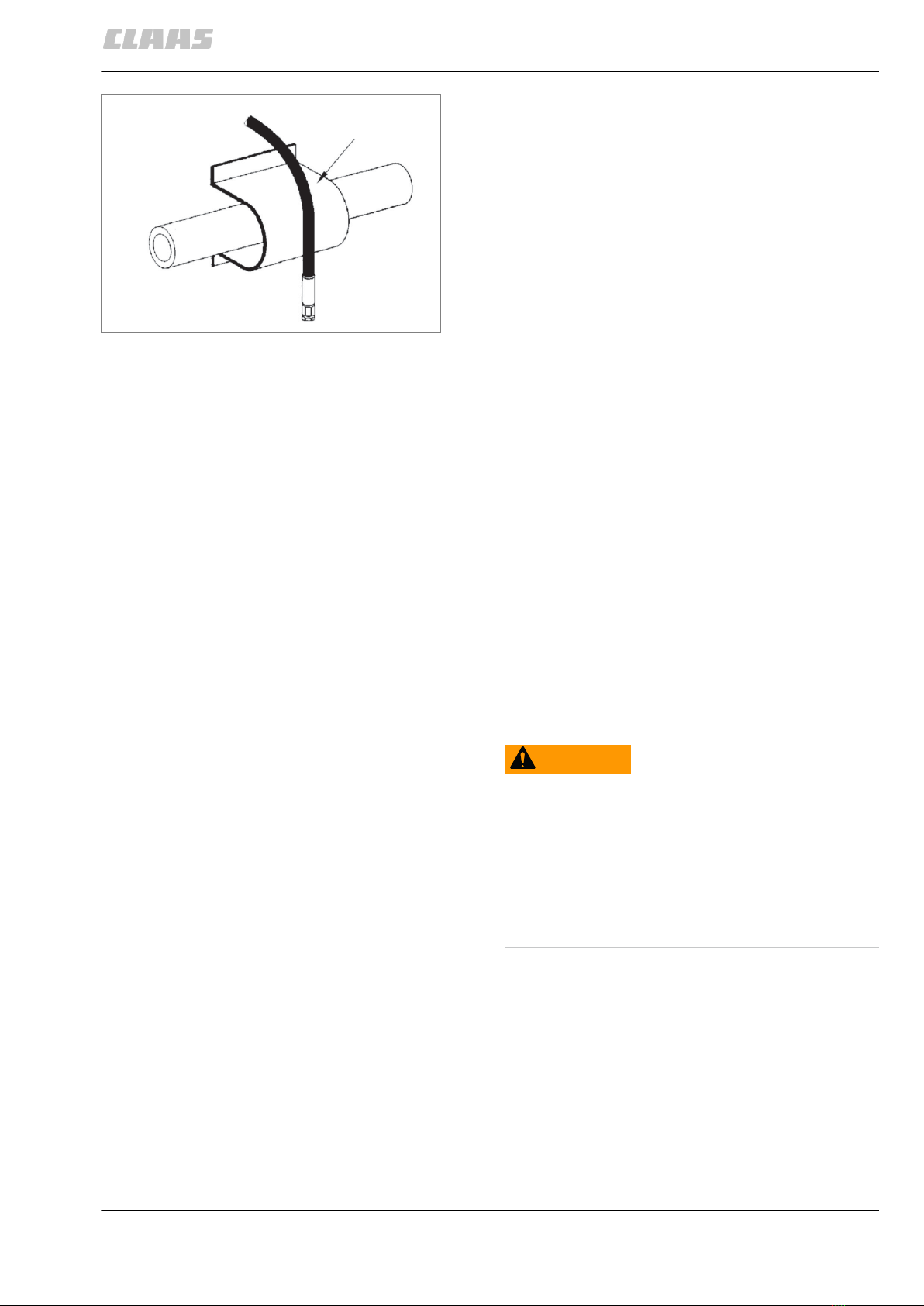
120856-007
Hydraulic hoses
124582-003
NOTICE
Failure of hydraulic hose lines due to ageing.
Uncontrolled lowering of machine parts.
► Replace hydraulic hose lines 6 years after
manufacture at the latest.
To facilitate identifying of hydraulic hoses, each hose
has the CLAAS part number printed on it.
►Check hydraulic hoses before initial
commissioning and thereafter at least once a
year.
►In the case of damage and ageing, replace
hydraulic hoses.
The date of manufacture can be seen on the hose
fittings (1).
(2) = year (e.g. 12 = 2012)
(3) = month (e.g. 07 = July)
32
1
23
154527-001
XXX / 250 bar/ 13/07
XXX / 250 bar
/ 13
/07
1
1
XXX / 250 bar / 13/07
32
24
40202-004
Introduction
General repair instructions
1044-004
00 0296 433 2 - RHB Dieselmotor OM906/926LA - 10/2014 17

Hose placement
13989-003
NOTICE! Hoses laid in a straight line get shorter as
the hydraulic pressure is built up. Valves may be torn
off.
► Always install hoses with a slight slack.
►Install hoses so that no tension or compression
loads will occur in any operating conditions.
► Check: If you shake the hose line in the
middle between two brackets/connectors
(e.g. clamps), the overall play of the hose
line should be at least 1 cm.
►Do not install hose with a twist.
► Particularly if there is movement at the hose
line.
►Avoid external mechanical impacts on hoses.
► Avoid chafing the hoses against each other
or against components through proper
placement and fastening.
► Keep an adequate distance from
components.
► Keep sharp-edged components covered at
all times.
►When high outside temperatures are involved,
install hose lines at a sufficient distance from
components radiating heat.
► If necessary, protect hose by a protective
guard.
25
5727-002
26
5728-002
27
5729-002
28
5726-002
Introduction
General repair instructions
1044-004
18 00 0296 433 2 - RHB Dieselmotor OM906/926LA - 10/2014
157962-002
Treatment of sealing faces
Close all oil, coolant and fuel bores thoroughly prior to
treating the sealing faces.
Ensure that when treating sealing faces of
components containing oil, coolant and fuel, no
abrasives are used. Loose particles cause pollution
and damage.
Ensure that no seal residues, rust, lime and
combustion residues end up in open components
(gearbox halves).
Remove sealing residues, rust, lime and combustion
residues only using scraping tools or cleaning agents.
123155-004
Spare parts
11210-003
WARNING
Use of unauthorised spare parts.
Death or serious injury.
► Spare parts must at least comply with the
technical standards required by the manufacturer
of the implement!
► We recommend using genuine CLAAS spare
parts.
►Please quote the machine identification number
when ordering spare parts or making technical
enquiries.
CLAAS will assume no liability whatsoever for
damage incurred as a result of the use of non-genuine
CLAAS parts, accessories, and ancillary equipment.
29
5730-002
Introduction
General repair instructions
1044-004
00 0296 433 2 - RHB Dieselmotor OM906/926LA - 10/2014 19

Torque settings
123194-003
Tightening torques for metric standard threads
The tightening torques specified below apply only
when:
–A friction coefficient of µ tot = 0.14 is achieved in
connection with thread lubricant.
To achieve this, a surface protection agent such
as A3C+L, Dacromet or Termosil is
recommended.
–No other tightening torque is specified in the
descriptive text.
–No additional screw retention is used, such as
MK-type bolts or liquid locking compound.
Tightening torque in Nm at a friction coefficient
μ tot = 0.14
Bolts and nuts
Strength class 8.8 10.9 12.9
Dimensions
Hex. bolts
ISO 4014 to ISO 4018
Cheese-head screws
ISO 4762
Hex. nuts
ISO 4032
M 4 2.9 4.3 5
M 5 5.8 8.5 10
M 6 10 14.5 17
M 8 24.5 36 42
M 10 48.5 71 83.5
M 12 83.5 123 144
M 14 133 196 229
M 16 207 304 355
M 18 296 422 494
M 20 417 594 695
M 22 570 813 951
M 24 718 1022 1196
M 27 1058 1506 1763
M 30 1437 2046 2395
M 33 1944 2770 3240
M 36 2500 3561 4167
M 39 3237 4610 5394
Introduction
Torque settings
1044-004
20 00 0296 433 2 - RHB Dieselmotor OM906/926LA - 10/2014
This manual suits for next models
1
Popular Engine manuals by other brands


Takegawa
Takegawa KSR110 instruction manual

Kohler
Kohler COMMAND 20-25 HP owner's manual

Briggs & Stratton
Briggs & Stratton 490000 - REV A Operator's manual

EuroLite
EuroLite 50301300 user manual

WEG
WEG WECM Installation, operation and maintenance manual

Briggs & Stratton
Briggs & Stratton 400000 Intek Operator's manual


