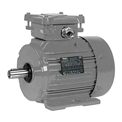
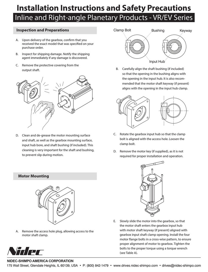
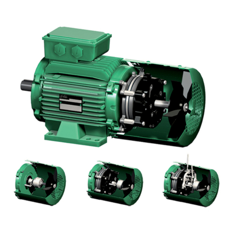
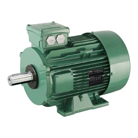
Nidec Leroy-Somer IMfinity LC Series User manual

3-phase induction motors
IE3 Premium efciency
Variable and xed speed
Frame size 315 to 500
150 to 1500 kW
IMnity®
Liquid cooled motors - LC series

The LC induction motors in this catalog are designed to achieve very high efciency
levels and operate at variable speed.
This catalog contains technical information about motors in the IE3 efciency class
(Premium efciency) which can be used on an A.C. supply and also on a drive.
On request, Leroy-Somer is able to offer IE4 motor solutions.
All the motors in this catalog can be used at variable speed depending on the specied
conditions.
All 2, 4 and 6-pole motors, rated 0.75 to 375 kW, offered for sale on the
European Union market must be efciency class IE3 or IE2 and used
with a variable speed drive:
- from 01/01/2015 for 7.5 to 375 kW ratings
- from 01/01/2017 for 0.75 to 375 kW ratings
In addition, to be eligible for efciency class IE3, the water inlet
temperature for water-cooled motors must be between 0°C and 32°C.

3
Leroy-Somer - Liquid-Cooled Motors - LC Series - 5370 en - 2017.05 / b
IMnity
®
- LC Liquid-Cooled 3-Phase Induction Motors
Contents
GENERAL
Introduction...........................................................................4
Quality Commitment .............................................................5
Directive and Standards Relating to Motor Efciency............6
Standards and Approvals......................................................7
Regulations in the Main Countries ......................................10
ENVIRONMENT
Denition of “Index of Protection”........................................11
Environmental Limitations...................................................12
Impregnation and Enhanced Protection..............................13
Heating ...............................................................................14
External Finish ....................................................................15
Interference Suppression and Protection of People ............16
CONSTRUCTION
Bearings and Bearing Life...................................................17
Lubrication and Maintenance of Bearings...........................18
OPERATION
Duty Cycle - Denitions.......................................................19
Supply Voltage....................................................................22
Insulation Class - Temperature Rise and
Thermal Reserve ................................................................24
Starting Times and Starting Current ....................................25
Power - Torque - Efciency - Power Factor (Cos ɸ) .............26
Noise Level.........................................................................29
Weighted Sound Level [dB(A).............................................30
Vibrations............................................................................31
Performance.......................................................................33
Starting Methods for Induction Motors ................................34
Braking ...............................................................................38
Use with a Variable Speed Drive .........................................40
Operation as an Asynchronous Generator..........................47
Special Environments.........................................................49
TECHNICAL CHARACTERISTICS
Designation.........................................................................50
Identication .......................................................................51
Description of an LC Motor basic conception ......................53
Cooling ...............................................................................54
Standard Equipment ...........................................................56
Optional Features ...............................................................57
Handling .............................................................................58
ELECTRICAL CHARACTERISTICS
IE3 Mains Supply................................................................59
IE3 Variable Speed Drive Supply ........................................61
Terminal Block Connection .................................................63
MECHANICAL CHARACTERISTICS
Mounting Arrangements......................................................64
Terminal Box Connection....................................................65
Dimensions of Shaft Extensions .........................................69
Dimensions of Foot Mounted IM 1001 (IM B3) ....................70
Dimensions of Foot and Flange Mounted IM 2001
(IM B35) ............................................................................. 71
Dimensions of Flange Mounted IM 3001 (IM B5)
IM 3011 (IMV1) ...................................................................72
Dimensions - Water Connecting Flange..............................73
Bearings and Lubrication ....................................................74
Axial Loads .........................................................................75
Radial Loads.......................................................................77
APPENDIX .........................................................................83
Congurator........................................................................91

4Leroy-Somer - Liquid-Cooled Motors - LC Series - 5370 en - 2017.05 / b
IMnity
®
- LC Liquid-Cooled 3-Phase Induction Motors
General
Introduction
In this catalog, Leroy-Somer describes high-efciency liquid-cooled induction motors. These motors have been designed to
incorporate the latest European standards, and can satisfy most of industry's demands. They are par excellence the leading
products on the Leroy-Somer liquid-cooled IMnity®platform.
Platform IMnity®
LSES
IE2 - IE3
Aluminum IP55
Frame size 80 to 315 mm
2, 4 and 6 poles
0.75 to 200 kW
LS
Non-IE
Aluminum IP55
Frame size 56 to 225 mm
2, 4 and 6 poles
0.09 to 45 kW
FLSES
IE2 - IE3
Cast iron IP55
Frame size 80 to 450 mm
2, 4 and 6 poles
0.75 to 900 kW
PLSES
IE3
IP23
Frame size 225 to 450 mm
2 and 4 poles
55 to 900 kW
LC
IE3
Liquid-cooled/IP55
Frame size 315 to 500 mm
2, 4 and 6 poles
150 to 1500 kW
Liquid-cooled motors are particularly suitable for and are used in applications requiring a low noise level, high output power with
IP55 protection, compact dimensions and operation on a drive.
Advantages
- Motor cooled by a water circuit integrated in the housing (IC71W)
- Reduced noise level: the water cooling system means the fan is no longer necessary and ensures a reduced noise level
(between 60 and 80 dB (A) in LpA
- IE3 Premium efciency across the whole range: 150 to 1500 kW - 2, 4 & 6-pole
- Compact design: weight and dimensions can be as much as 25% less than an air-cooled IP55 motor, and as much as 55% less
than an IP55 motor cooled by an air/water exchanger (IC81W)
- Degree of protection higher than IP55 (e.g.: IP56) as an option
- Motor adapted for use at constant torque across the entire speed range from 0 to 50 Hz, without derating. The motor is always
cooled, whatever the point of operation.
- Reduced vibration level
- Heat recovery thanks to dissipation of losses by an external water circuit
Application areas
- Marine: main propulsion and bow thruster units, equipment
on the bridge of the ship
- Test benches: automotive, aeronautics
- Pumps, compressors, agitators, mixers
- Plastics industries: extrusion and plastic injection machines
- Hydraulic turbines
- Heavy industries: iron and steel, cement, chemical industries

5
Leroy-Somer - Liquid-Cooled Motors - LC Series - 5370 en - 2017.05 / b
IMnity
®
- LC Liquid-Cooled 3-Phase Induction Motors
General
Quality Assurance
Leroy-Somer's quality management
system is based on:
- Tight control of procedures right from
the initial sales offering through to
delivery to the customer, including the
design process, manufacturing start-
up and production.
- A total quality policy based on making
continuous progress in improving
operational procedures, involving all
departments in the company in order
to give customer satisfaction as
regards delivery times, conformity and
cost.
- Indicators used to monitor process
performance.
- Corrective actions and advancements
with tools such as FMECA, QFD,
MAVP, MSP/MSQ and Hoshin type
improvement workshops on ows,
process re-engineering, plus Lean
Manufacturing and Lean Ofce.
- Annual surveys, opinion polls and
regular visits to customers in order to
ascertain and detect their expectations.
Personnel are trained and take part in
the analyses and the actions for
continuously improving the procedures.
A special study of the motors in this
catalog has been conducted to measure
the impact of their life cycle on the
environment. This eco-design process
has resulted in the creation of a “Product
Environmental Prole” (references
4592/4950/4951).
Leroy-Somer has entrusted the
certication of its expertise to various
international organizations.
Certication is granted by independent
professional auditors, and recognizes
the high standards of the company's
quality assurance procedures. All
activities resulting in the nal version of
the machine have therefore received
ofcial ISO 9001:2008 certication from
the DNV.
Similarly, our environmental approach
has enabled us to obtain ISO 14001:
2004 certication.
Products for particular applications or
those designed to operate in specic
environments are also approved or
certied by the following organizations:
LCIE, DNV, INERIS, EFECTIS, UL,
BSRIA, TUV, GOST, which check their
technical performance against the
various standards or recommendations.
ISO 9001 : 2008

6Leroy-Somer - Liquid-Cooled Motors - LC Series - 5370 en - 2017.05 / b
IMnity
®
- LC Liquid-Cooled 3-Phase Induction Motors
General
There have been a number of changes
to the standards and new standards
created in recent years. They mainly
concern motor efciency and their
scope includes measurement methods
and motor classication.
Regulations are gradually being
implemented, both nationally and
internationally, in many countries in order
to promote the use of high-efciency
motors (Europe, USA, Canada, Brazil,
Australia, New Zealand, Korea, China,
Israel, etc.).
The new generation of Premium
efciency three-phase induction motors
responds to changes in the standards
as well as the latest demands of system
integrators and users.
STANDARD IEC 60034-30-1
(January 2014) denes the principle
to be adopted and brings global
harmonization to energy efciency
classes for electric motors throughout
the world.
Motors concerned
Induction or permanent magnet, single-
phase and three-phase single-speed
cage motors, on a sinusoidal A.C.
supply.
Scope:
-Unfrom 50 to 1000 V
- P
nfrom 0.12 to 1000 kW
- 4, 6 and 8 poles
- Continuous duty at rated power
without exceeding the specied
insulation class. Generally known as
S1 duty.
- 50 and 60 Hz frequency
- On the A.C. supply
-Rated for an ambient temperature
between -20°C and +60°C
- Rated for altitude up to 4000 m
- Water inlet temperature from 0°C to
+32°C
Motors not concerned
- Motors with frequency inverter when
the motor cannot be tested without it.
- Brake motors when they form an
integral part of the motor construction
and can neither be removed nor
supplied separately in order to be
tested.
- Motors which are fully integrated
in a machine and cannot be tested
separately (such as rotor/stator).
STANDARD FOR MEASURING
THE EFFICIENCY OF
ELECTRIC MOTORS: IEC
60034-2-1 (September 2007)
Standard IEC 60034-2-1 concerns
asynchronous induction motors:
- Single-phase and three-phase with
power ratings of 1 kW or less. The
preferred method is the D.O.L.
method
- Three-phase motors with power
ratings above 1 kW. The preferred
method is the summation of losses
method with the total of additional
losses measured.
Comments:
- The standard for efciency
measurement is very similar to the
IEEE 112-B method used in North
America.
-Since the measurement method is
different, this means that for the same
motor, the rated value will be different
(usually lower) with IEC 60034-2-1 than
with IEC 60034-2.
DIRECTIVE 2009/125/EC
(21 October 2009)
from the European Parliament
established a framework for setting the
eco-design requirements to be applied
to “energy-using products”. These
products are grouped in lots. Motors
come under lot 11 of the eco-design
program, as do pumps, fans and
circulating pumps.
DECREE IMPLEMENTING
EUROPEAN DIRECTIVE ErP
(Energy Related Product)
EC/640/2009 - LOT 11
(July 2009) + EU/4/2014
(January 2014)
This is based on standard IEC
60034-30-1 and will dene the efciency
classes whose use will be mandatory
in the future. It species the efciency
levels to be attained for machines sold
in the European market and outlines the
timetable for their implementation.
Efciency classes Efciency level
IE1 Standard
IE2 High
IE3 Premium
IE4 Super Premium
This standard only denes efciency
classes and their conditions. It is
then up to each country to dene the
efciency classes and the exact scope
of application.
EUROPEAN DIRECTIVE ErP
Motors concerned: 2-, 4- and 6-pole
induction motors between 0.75 and
375 kW.
Obligation to place high-efciency
or Premium efciency motors on the
market:
- IE2 class from 16 June 2011
- Class IE3* from 1 January 2015 for
power ratings from 7.5 to 375 kW
- Class IE3* from 1 January 2017 for
power ratings from 7.5 to 375 kW
The European Commission is currently
working to dene minimum efciency
values for drives.
*or IE2 motor + drive
Motors not concerned:
- Motors designed to operate when
fully submerged in liquid
- Motors which are fully integrated in
another product (rotor/stator)
- Motors with duty other than
continuous duty
- Motors designed to operate in the
following conditions:
• Altitude > 4000 m
• Ambient air temperature > 60°C
• Maximum operating temperature
> 400°C
• Ambient air temperature < -30°C or
< 0°C for air-cooled motors
• Cooling water temperature at
product inlet
< 0°C or > 32°C
• Safety motors conforming to
directive ATEX 94/9/EC
• Brake motors
• Onboard motors
Directive and Standards Relating to Motor Efciency
7
Leroy-Somer - Liquid-Cooled Motors - LC Series - 5370 en - 2017.05 / b
IMnity
®
- LC Liquid-Cooled 3-Phase Induction Motors
General
Standards and Approvals
LIST OF STANDARDS QUOTED IN THIS DOCUMENT
Reference International Standards
IEC 60034-1 EN 60034-1 Rotating electrical machines: rating and performance.
IEC 60034-2 Rotating electrical machines: methods for determining losses and efciency from tests
(additional losses added as a xed percentage).
IEC 60034-2-1 Rotating electrical machines: methods for determining losses and efciency from tests
(additional losses added as a measured percentage).
IEC 60034-5 EN 60034-5 Rotating electrical machines: classication of degrees of protection provided by casings
of rotating machines.
IEC 60034-6 EN 60034-6 Rotating electrical machines (except traction): methods of cooling
IEC 60034-7 EN 60034-7 Rotating electrical machines (except traction): symbols for mounting positions and assembly layouts
IEC 60034-8 Rotating electrical machines: terminal markings and direction of rotation
IEC 60034-9 EN 60034-9 Rotating electrical machines: noise limits
IEC 60034-12 EN 60034-12 Starting performance of single-speed three-phase cage induction motors for supply voltages up to and including 660 V.
IEC 60034-14 EN 60034-14 Rotating electrical machines: mechanical vibrations of certain machines with a frame size above or equal to 56 mm.
Measurement, evaluation and limits of vibration severity
IEC 60034-17 Cage induction motors when fed from converters - Application guide
IEC 60034-30-1 Rotating electrical machines: efciency classes of single-speed, three-phase cage induction motors
(IE code).
IEC 60038 IEC standard voltages.
IEC 60072-1 Dimensions and output powers for rotating electrical machines: designation of casings between 56 and 400 and anges
between 55 and 1080
IEC 60085 Evaluation and thermal classication of electrical insulation
IEC 60721-2-1 Classication of environmental conditions. Temperature and humidity
IEC 60892 Effects of unbalanced voltages on the performance of 3-phase cage induction motors
IEC 61000-2-10/11 and 2-2 Electromagnetic compatibility (EMC): environment.
IEC guide 106 Guide for specifying environmental conditions for equipment performance rating
ISO 281 Bearings - Dynamic load ratings and nominal bearing life
ISO 1680 EN 21680 Acoustics - Test code for the measurement of airborne noise emitted by rotating electrical machines:
a method for establishing an expert opinion for free eld conditions over a reective surface.
ISO 8821 Mechanical vibration - Balancing. Shaft and tment key conventions.
EN 50102 Degree of protection provided by electrical enclosures against extreme mechanical impacts
ISO 12944-2 Corrosion protection

8Leroy-Somer - Liquid-Cooled Motors - LC Series - 5370 en - 2017.05 / b
IMnity
®
- LC Liquid-Cooled 3-Phase Induction Motors
General
Standards and Approvals
MAIN PRODUCT MARKINGS WORLDWIDE
Special markings are in place all over the world. They primarily concern product compliance with safety standards for users in force
in countries. Some markings or labels only apply to energy regulations. One country can have two different markings: one for safety
and one for energy.
C US
C US
C US
ee
This marking is mandatory in the European Economic Community market. It means that the product complies with all relevant
directives. If the product does not comply with an applicable directive, it cannot be CE-rated and hence cannot bear the CE mark.
C US
C US
C US
ee
In Canada and the United States: The CSA mark accompanied by the letters C and US mean that the product is certied for the
American and Canadian markets, according to the relevant American and Canadian standards. If a product has characteristics arising
from more than one product genre (e.g.: electrical equipment including fuel combustion), the mark indicates compliance with all
relevant standards.
C US
C US
C US
ee
This mark only applies to nished products such as complete machines. A motor is only a component and is not therefore affected by
this marking.
Note: c CSA us and c UL us mean the same thing but one is awarded by the CSA and the other by UL.
C US
C US
C US
ee
The c UL us mark, which is optional, indicates compliance with Canadian requirements and those of the United States. UL encourages
manufacturers distributing products with the Recognized UL mark for both countries to use this combined mark.
For Canada, c UR us or c CSA us is a minimum requirement. It is also possible to have both.
Components covered by the UL “Recognized Mark” program are destined for installation in another device, system or end product. They will be installed in the factory, not in the
eld, and it is possible that their performance capacity will be restricted, limiting their use. When a product or complete system containing UL Recognized components is assessed,
the process of assessing the end product can be rationalized.
Canada: energy efciency compliance logo (optional).
C US
C US
C US
ee
USA: energy efciency compliance logo (optional.
USA and Canada: EISA commercial compliance logo (optional).
C US
C US
C US
ee
This marking is mandatory for the Chinese market. It indicates that the product complies with current regulations (user safety). It
concerns electric motors rated ≤ 1.1 kW.
The EAC mark has replaced the GOST mark. It is the equivalent of the CE mark for the European Union market. This new mark covers
regulations for Russia, Kazakhstan and Belarus. All products offered for sale in these three countries must bear this mark.
Other marks concern certain applications such as ATEX for example.

9
Leroy-Somer - Liquid-Cooled Motors - LC Series - 5370 en - 2017.05 / b
IMnity
®
- LC Liquid-Cooled 3-Phase Induction Motors
General
INTERNATIONAL AND NATIONAL STANDARD EQUIVALENTS
International reference standards National standards
IEC Title (summary) FRANCE GERMANY UK ITALY SWITZERLAND
60034-1 Ratings and operating characteristics
NFEN 60034-1
NFC 51-120
NFC 51-200
DIN/VDE O530 BS 4999 CEI 2.3.VI. SEV ASE 3009
60034-5 Classication of degrees of protection NFEN 60034-5 DIN/EN 60034-5 BS EN 60034-5 UNEL B 1781
60034-6 Cooling methods NFEN 60034-6 DIN/EN 60034-6 BS EN 60034-6
60034-7 Mounting arrangements and assembly layouts NFEN 60034-7 DIN/EN 60034-7 BS EN 60034-7
60034-8 Terminal markings and direction of rotation NFC 51 118 DIN/VDE 0530
Teil 8 BS 4999-108
60034-9 Noise limits NFEN 60034-9 DIN/EN 60034-9 BS EN 60034-9
60034-12 Starting characteristics for single-speed motors
for supply voltages ≤ 660 V NFEN 60034-12 DIN/EN 60034-12 BS EN 60034-12 SEV ASE 3009-12
60034-14 Mechanical vibrations of machines with
frame size ≥56 mm NFEN 60034-14 DIN/EN 60034-14 BS EN 60034-14
60072-1
Dimensions and output powers for machines
of between 56 and 400 frame and anges
of between 55 and 1080.
NFC 51 104
NFC 51 105
DIN 748 (~)
DIN 42672
DIN 42673
DIN 42631
DIN 42676
DIN 42677
BS 4999
60085 Evaluation and thermal classication
of electrical insulation. NFC 26206 DIN/EN 60085 BS 2757 SEV ASE 3584
Note: DIN 748 tolerances do not conform to IEC 60072-1.
Standards and Approvals

10 Leroy-Somer - Liquid-Cooled Motors - LC Series - 5370 en - 2017.05 / b
IMnity
®
- LC Liquid-Cooled 3-Phase Induction Motors
General
Regulations in the Main Countries
Many countries have already
implemented
energy regulations
concer
ning electric motors. Others are in
the process of preparing them.
Some regulations require that before
they can be offered for sale, products
must be registered with the local
authorities. In these cases, market
surveillance is undertaken before the
products are put into use, unlike the EU
where the member states are responsible
for organizing surveillance on their own
territory.
The majority of countries requiring
registration before products are offered
for sale also usually require special
product labeling.
For Europe, there is no special label.
Only CE marking indicates that the
product complies with all the relevant
directives.
As regulations are constantly changing
and vary from country to country, it is
advisable to check for updates on a
regular basis.
For more details of the efciency classes
applicable for each power rating and
number of motor poles according to the
timetable, please contact your local
Leroy-Somer sales ofce.

11
Leroy-Somer - Liquid-Cooled Motors - LC Series - 5370 en - 2017.05 / b
IMnity
®
- LC Liquid-Cooled 3-Phase Induction Motors
Environment
INGRESS PROTECTION OF ELECTRICAL EQUIPMENT ENCLOSURES
In accordance with IEC 60034-5 - EN 60034-5 (IP) - IEC 62262 (IK)
IP
0
1
2
3
4
5
Tests Definition IP Tests Definition IK Tests Definition
1st number:
Protection against solid objects
3rd number:
Mechanical protection
Ø 50 mm
Ø 12 mm
No protection
Ø 2.5 mm
Ø 1 mm
2nd number:
Protection against liquids
0No protection 00 No protection
1
15°
2
3
4
60°
5
6
7
8..m
0.15 m
1 m
01 Impact energy:
0.15 J
02 Impact energy:
0.20 J
03 Impact energy:
0.37 J
05 Impact energy:
0.70 J
07 Impact energy:
2 J
09 Impact energy:
10 J
150 g
10 cm
250 g
15 cm
250 g
20 cm
250 g
40 cm
0.5 kg
40 cm
2.5 kg
40 cm
. . m
6
200 g
10 cm
350 g
20 cm
04
06
08 1.25 kg
40 cm
10 Impact energy:
20 J
5 kg
40 cm
Impact energy:
5 J
Impact energy:
1 J
Impact energy:
0.50 J
Protected against
solid objects larger
than 50 mm (e.g.
accidental contact
with the hand)
Protected against
solid objects larger
than 12 mm
(e.g. a finger)
Protected against
solid objects larger
than 2.5 mm
(e.g. tools, wires)
Protected against
solid objects larger
than 1 mm (e.g. thin
tools, small wires)
Protected against
dust (no deposits of
harmful material)
Protected against
any dust
penetration
Protected against
water drops falling
vertically
(condensation)
Protected against
water drops falling
at up to 15° from
the vertical
Protected against
rain falling at up
to 60° from the
vertical
Protected against
projected water
from all directions
Projected against
jets of water from
all directions
from a hose
Protected against
projected water
comparable to
big waves
Protected against
the effects of
immersion between
0.15 and 1 m
Protected against
prolonged effects
of immersion
under pressure
Example:
Example of a liquid-cooled IP 55 machine
IP : Protection index
5. : Machine protected against dust and accidental contact.
Test result: no dust enters in harmful quantities, no risk of direct contact with
rotating parts. The test will last for 2 hours.
.5 : Machine protected against jets of water from all directions from hoses at 3 m
distance with a ow rate of 12.5 l/min at 0.3 bar.
The test will last for 3 minutes.
Test result: no damage from water projected onto the machine.
Denition of “Index of Protection” (IP)

12 Leroy-Somer - Liquid-Cooled Motors - LC Series - 5370 en - 2017.05 / b
IMnity
®
- LC Liquid-Cooled 3-Phase Induction Motors
Environment
NORMAL OPERATING
CONDITIONS
According to IEC 60034-1,
motors can operate in the
following normal conditions:
• ambient temperature between -16°C
and +40°C
• altitude less than 1000 m
• atmospheric pressure: 1050 hPa
(mbar) = (750 mm Hg)
The ambient temperature must not be
less than +5°C for water-cooled motors.
If this is the case, antifreeze must be
added to the water for temperatures less
than +5°C.
Special operating conditions can be
discussed on request.
NORMAL STORAGE
CONDITIONS
The storage area must be closed and
covered, protected against mold, vapors
and other harsh, corrosive (chemical)
substances. The storage area ambient
temperature must be between +5°C and
+60°C, at a relative humidity of less than
50%, and must not be subject to sudden
temperature variations. Storage
outdoors is not recommended.
For restarting, see commissioning
manual.
RELATIVE AND ABSOLUTE
HUMIDITY
Measuring the humidity:
Humidity is usually measured by the
“wet and dry bulb thermometer” method.
Absolute humidity, calculated from the
readings taken on the two thermometers,
can be determined using the above
chart. The chart also provides relative
humidity gures.
To determine the humidity correctly, a
good air ow is required for stable
readings, and accurate readings must
be taken on the thermometers.
DRAIN HOLES
Holes are provided at the lowest points
of the housing, depending on the
operating position (IM, etc.) to drain off
anymoisture thatmayhaveaccumulated
inside during cooling of the machine.
As standard, the holes are sealed with
metal plugs.
Under certain special conditions, it is
advisable to leave the drain holes
permanently open (operating in
environments with high levels of
condensation). Opening the holes
periodically should be part of the regular
maintenance procedures.
Environmental Limitations
In temperate climates, relative humidity is generally between 50 and 70%. For the relationship
between relative humidity and motor impregnation, especially where humidity and temperature
are high, see table on next page.
10
Ambient temperature - dry bulb thermometer
Absolute air humidity
20 30 40 50 60
10
20
30
40
5
10
15
20
25
30
W
e
t
b
u
l
b
t
h
e
r
m
o
m
e
t
e
r
t
e
m
p
e
r
a
t
u
r
e
°
C
°C
g/m3
20
40
60
80
100
%
Relative air humidity

13
Leroy-Somer - Liquid-Cooled Motors - LC Series - 5370 en - 2017.05 / b
IMnity
®
- LC Liquid-Cooled 3-Phase Induction Motors
Environment
NORMAL ATMOSPHERIC PRESSURE (750 MM HG)
The selection table below can be used to nd the method of manufacture best suited to particular environments in which temperature
and relative humidity show large degrees of variation (see relative and absolute humidity calculation method, on preceding page).
The winding protection is generally described by the term "tropicalization".
For high humidity environments, we recommend that the windings are pre-heated (see next page).
Relative
humidity RH ≤ 95% RH ≥ 95%*
Ambient
temperature
T° < -16°C Please consult LS Please consult LS
-16°C to +50°C Standard Tropicalization
T° > +50°C Please consult LS Please consult LS
Inuence on
construction Stainless steel screws as standard Tropicalization:
rotor and stator protection
* Atmosphere without high levels of condensation
Tropicalization refers to protection of the motor's electrical parts (rotor, stator and coil end turns).
It is available as an option for all motor versions.
Impregnation and Enhanced Protection

14 Leroy-Somer - Liquid-Cooled Motors - LC Series - 5370 en - 2017.05 / b
IMnity
®
- LC Liquid-Cooled 3-Phase Induction Motors
Environment
Heating
SPACE HEATERS
Severe climatic conditions may require
the use of space heaters (tted to the
motor windings) which serve to maintain
the average temperature of the motor,
provide trouble-free starting, and
eliminate problems caused by
condensation (loss of insulation).
The heater supply wires are brought out
to a terminal block in the motor's auxiliary
terminal box.
The heaters must be switched off while
the motor is running.
Table of space heater power ratings
by type of LC motor
Motor type Power (W)
LC 315 LA/LB 150
LC 315 LKA/LKB/LKC
200
LC 355 LA/LB/LC
LC 355 LKA/LKB/LKC
300
LC 400 LA
LC 400 LKA
LC 450 LA/LB
LC 500 M/L 400
The space heaters use 200/240 V,
single-phase, 50 or 60 Hz.
A.C. INJECTION HEATING
A single-phase A.C. voltage (from 10 to
15% of rated voltage), can be used
between 2 phases placed in series.
This method can be used on the whole
motor range.
This function can be performed by a
frequency inverter.

15
Leroy-Somer - Liquid-Cooled Motors - LC Series - 5370 en - 2017.05 / b
IMnity
®
- LC Liquid-Cooled 3-Phase Induction Motors
Environment
External Finish
Surface protection is dened in standard ISO 12944. This standard denes the expected life of a paint system until the rst major
application of maintenance paint. Durability is not guaranteed.
Standard EN ISO 12944 is divided into 8 parts. Part 2 discusses the classication of environments.
Leroy-Somer motors are protected with a range of surface nishes.
Surfaces receive appropriate special treatments, as shown below.
Leroy-Somer standard paint color reference:
PREPARATION OF SURFACES
Surface Parts Surface treatment
Cast iron End shields Shot blasting + Primer
Steel
Accessories Phosphate treatment + Primer
Terminal boxes - Fan covers - End shields Electrostatic painting or Epoxy powder
CLASSIFICATION OF ENVIRONMENTS
Leroy-Somer paint systems according to category.
Atmospheric
corrosivity
categories
Corrosivity
category*
a/c to ISO 12944-2
Durability class
ISO 6270 ISO 9227 Form
LS
Leroy-Somer system
equivalent
Water condensation
Number of hours
Neutral saline mist
Number of hours
MEDIUM C3
Medium 120 240 101b IIa
High 240 480 132b
IIb
standard for
LC motors
HIGH C4
Limited 120 240 - -
Medium 240 480 102c IIIa
High 480 720 106b IIIb**
VERY HIGH
(Industry) C5-I
Limited 240 480 165 IVb**
Medium 480 720 140b Ve**
High 720 1440 - -
VERY HIGH
(Marine) C5-M
Limited 240 480 --
Medium 480 720 - -
High 720 1440 161b 161b**
* Values given for information only since the substrates vary in nature whereas the standard only takes account of steel substrates.
** Assessment of degree of rusting in accordance with standard ISO 4628 (rust over 1 to 0.5% of the surface).
CORROBLOC FINISH AVAILABLE AS AN OPTION
Component Materials Comments
Stator-Rotor Dielectric and anti-corrosion protection
Nameplates Stainless steel Nameplate: indelible marking
Screws Stainless steel
Cable glands Brass
External nish System IIIa
Note: On LC motors, the screws and nameplates are routinely made of stainless steel.
RAL 6000

16 Leroy-Somer - Liquid-Cooled Motors - LC Series - 5370 en - 2017.05 / b
IMnity
®
- LC Liquid-Cooled 3-Phase Induction Motors
Environment
Interference Suppression and Protection of People
AIRBORNE INTERFERENCE
EMISSION
For standard motors, the housing acts as
an electromagnetic screen, reducing
electromagnetic emissions measured at
0.25 meters from the motor to
approximately 5 gauss (5 x 10⁻⁴ T).
However, electromagnetic emissions
can be noticeably reduced by a specially-
constructed stainless steel shaft.
IMMUNITY
The construction of the motor housings
isolates external electromagnetic
sources to the extent that any eld
penetrating the casing and magnetic
circuit will be too weak to interfere with
the operation of the motor.
POWER SUPPLY
INTERFERENCE
The use of electronic systems for
starting, variable speed control or power
supply can create harmonics on the
supply lines that may interfere with
operation of the machines. These
phenomena are taken into account in
determining the machine dimensions,
which act as quenching chokes in this
respect.
The IEC 61000 standard, currently in
preparation, will dene permissible
rejection and immunity rates: only then
will machines for general distribution
(especially single-phase motors and
commutator motors) have to be tted
with suppression systems.
Three-phase squirrel cage machines do
not in themselves produce interference
of this type. A.C. supply connection
equipment (contactors) may, however,
need interference protection.
APPLICATION OF DIRECTIVE
2004/108/EC CONCERNING
ELECTROMAGNETIC
COMPATIBILITY (EMC)
a - for motors only
According to amendment 1 of IEC
60034-1, induction motors are not
transmitters and do not produce
interference (via carried or airborne
signals) and therefore conform inherently
to the essential requirements of the EMC
directives.
b - for motors supplied by inverters
(at xed or variable frequency)
In this case, the motor is only a sub-
assembly of a device which the system
builder must ensure conforms to the
essential requirements of the EMC
directives.
APPLICATION OF LOW
VOLTAGE DIRECTIVE
2006/95/EC
All motors are subject to this directive.
The main requirements concern the
protection of people, animals and
property against risks caused by
operation of the motors (see the
commissioning and maintenance
manual for precautions to be taken).
APPLICATION OF
MACHINERY DIRECTIVE
2006/42/EC
All motors are designed to be integrated
in a device subject to the machinery
directive.
MARKING OF PRODUCTS
The fact that motors comply with the
essential requirements of the Directives
is shown by the CE mark on their
nameplates and/or packaging and
documentation.

17
Leroy-Somer - Liquid-Cooled Motors - LC Series - 5370 en - 2017.05 / b
IMnity
®
- LC Liquid-Cooled 3-Phase Induction Motors
Construction
Bearings and Bearing Life
DEFINITIONS
LOAD RATINGS
Static load rating Co:
This is the load for which permanent
deformation at point of contact between
a bearing race and the ball (or roller) with
the heaviest load reaches 0.01% of the
diameter of the ball (or roller).
Dynamic load rating C:
This is the load (constant in intensity and
direction) for which the nominal lifetime
of the bearing will reach 1 million
revolutions.
The static load rating Coand dynamic
load rating C are obtained for each
bearing by following the method in
ISO 281.
LIFETIME
The lifetime of a bearing is the number of
revolutions (or number of operating
hours at a constant speed) that the
bearing can accomplish before the rst
signs of fatigue (spalling) begin to appear
on a ring, ball or roller.
Nominal lifetime L10h
According to the ISO recommendations,
the nominal lifetime is the length of time
completed or exceeded by 90% of
apparently identical bearings operating
under the conditions specied by the
manufacturer.
Note: The majority of bearings last much
longer than the nominal lifetime; the
average lifetime achieved or exceeded
by 50% of bearings is around 5 times
longer than the nominal lifetime.
DETERMINATION OF NOMINAL
LIFETIME
Constant load and speed of rotation
The nominal lifetime of a bearing
expressed in operating hours L10h, the
dynamic load rating C expressed in daN
and the applied loads (radial load Frand
axial load Fa) are related by the following
equation:
L10h=
Nm=
Pm=
1000000
60 Nm
.
----------------------- C
Pm
----
(
)p
.
L10h=
1000000
60 N.
----------------------- C
P
----
( )p
.
N1
q1
100
---------- N2
q2
100
---------- …min1–
( )+.+.
P1
PN1
Nm
------ q1
100
----- P2
PN2
Nm
------ q2
100
----- …++
PdaN( )
. . . .
( ) ( )
where N = speed of rotation (rpm)
P (P = X Fr + Y Fa): dynamic load
equivalent (Fr, Fa, P in daN)
p: exponent which is a function of the
contact between the races and balls
(or rollers)
p = 3 for ball bearings
p = 10/3 for roller bearings
The formulae that give Equivalent
Dynamic Load (values of factors X and
Y) for different types of bearing can be
obtained from their respective
manufacturers.
Variable load and speed of rotation
For bearings with periodically variable
load and speed, the nominal lifetime is
established using the equation:
L10h=
Nm=
Pm=
1000000
60 Nm
.
----------------------- C
Pm
----
(
)p
.
L10h=
1000000
60 N.
----------------------- C
P
----
( )p
.N1
q1
100
---------- N2
q2
100
---------- …min1–
( )+.+.
P1
PN1
Nm
------ q1
100
----- P2
PN2
Nm
------ q2
100
----- …++
PdaN( )
. . . .
( ) ( )
Nm: average speed of rotation
L10h=
Nm=
Pm=
1000000
60 Nm
.
----------------------- C
Pm
----
(
)p
.
L10h=
1000000
60 N.
----------------------- C
P
----
( )p
.
N1
q1
100
---------- N2
q2
100
---------- …min1–
( )+.+.
P1
PN1
Nm
------ q1
100
----- P2
PN2
Nm
------ q2
100
----- …++
PdaN( )
. . . .
( ) ( )
Pm: average equivalent dynamic load
L10h=
Nm=
Pm=
1000000
60 Nm
.
----------------------- C
Pm
----
(
)p
.
L10h=
1000000
60 N.
----------------------- C
P
----
( )p
.N1
q1
100
---------- N2
q2
100
---------- …min1–
( )+.+.
P1
PN1
Nm
------ q1
100
----- P2
PN2
Nm
------ q2
100
----- …++
PdaN( )
. . . .
( ) ( )
with q1, q2, etc. as a %
Nominal lifetime L10h is applicable to
bearings made of bearing steel and
normal operating conditions (lubricating
lm present, no contamination, correctly
tted, etc.).
Situations and data differing from these
conditions will lead to either a reduction
or an increase in lifetime compared to
the nominal lifetime.
Corrected nominal lifetime
If the ISO recommendations (DIN ISO 281)
are used, improvements to bearing
steel, manufacturing processes and the
effects of operating conditions can be
included in the nominal lifetime
calculation.
The theoretical pre-fatigue lifetime Lnah is
thus calculated using the formula:
Lnah = a1a2a3L10h
where:
a1: failure probability factor
a2: factor for the
characteristics and tempering of the
steel
a3: factor for the operating conditions
(lubricant quality, temperature, speed of
rotation, etc.).
Speed N
Nm
N1 N4
N2
N3
Load P
Pm
P1
P4
P2
P3
100%
q1% q2% q3% q4%
q1% q2% q3% q4%
Time
Time

18 Leroy-Somer - Liquid-Cooled Motors - LC Series - 5370 en - 2017.05 / b
IMnity
®
- LC Liquid-Cooled 3-Phase Induction Motors
Construction
Lubrication and Maintenance of Bearings
ROLE OF THE LUBRICANT
The principal role of the lubricant is to
avoid direct contact between the metal
parts in motion: balls or rollers, slip-rings,
cages, etc. It also protects the bearing
against wear and corrosion.
The quantity of lubricant needed by a
bearing is normally quite small. There
should be enough to provide good
lubrication without undesirable
overheating. As well as lubrication itself
and the operating temperature, the
amount of lubricant should be judged by
considerations such as sealing and heat
dissipation.
The lubricating power of a grease or an
oil lessens with time owing to mechanical
constraints and straightforward aging.
Used or contaminated lubricants should
therefore be replaced or topped up with
new lubricant at regular intervals.
Bearings can be lubricated with grease,
oil or, in certain cases, with a solid
lubricant.
GREASING
A lubricating grease can be dened as a
product of semi-uid consistency
obtainedbythe dispersion ofathickening
agent in a lubricating uid and that may
contain several additives to give it
particular properties.
Composition of a grease
Base oil: 85 to 97%
Thickener: 3 to 15%
Additives: 0 to 12%
THE BASE OIL LUBRICATES
The oil making up the grease is of prime
importance. It is the oil that lubricates
the moving parts by coating them with a
protective lm which prevents direct
contact. The thickness of the lubricating
lm is directly linked to the viscosity of
the oil, and the viscosity itself depends
on temperature. The two main types
used to make grease are mineral oils
and synthetic oils. Mineral oils are
suitable for normal applications in a
range of temperatures from -30°C to
+150°C.
Synthetic oils have the advantage of
being effective in severe conditions
(extreme variations of temperature,
harsh chemical environments, etc.).
THE THICKENER GIVES THE
GREASE CONSISTENCY
The more thickener a grease contains,
the “harder” it will be. Grease consistency
varies with the temperature. In falling
temperatures, the grease hardens
progressively, and the opposite happens
when temperatures rise.
The consistency of a grease can be
quantied using the NLGI (National
Lubricating Grease Institute)
classication. There are 9 NLGI grades,
from 000 for the softest greases up to 6
for the hardest. Consistency is expressed
by the depth to which a cone can be
driven into a grease maintained at 25°C.
If we only consider the chemical nature of
the thickener, lubricating greases fall into
three major categories:
•Conventional greases with a metallic
soap base (calcium, sodium, aluminum,
lithium). Lithium soaps have several
advantages over other metallic soaps: a
high melting point (180° to 200°), good
mechanical stability and good water-
resistant properties.
• Greases with a complex soap base.
The main advantage of this type of soap
is a very high melting point (over 250°C).
•Soapless greases. The thickener is an
inorganic compound, such as clay. Their
main property is the absence of a melting
point, which makes them practically non-
liquefying.
ADDITIVES IMPROVE SOME
PROPERTIES OF GREASES
Additives fall into two types, depending
on whether or not they are soluble in the
base oil.
The most common insoluble additives -
graphite, molybdenum disulphide, talc,
mica, etc., improve the friction
characteristics between metal surfaces.
They are therefore used in applications
where heavy pressure is required.
The soluble additives are the same as
those used in lubricating oils:
antioxidants, anti-rust agents, etc.
LUBRICATION TYPE
The bearings are lubricated with a
polyurea soap-based grease.

19
Leroy-Somer - Liquid-Cooled Motors - LC Series - 5370 en - 2017.05 / b
IMnity
®
- LC Liquid-Cooled 3-Phase Induction Motors
Operation
Duty Cycle - Denitions
DUTY CYCLES
(IEC 60034-1)
The typical duty cycles are described
below:
1 - Continuous duty - Type S1
Operation at constant load of sufcient
duration for thermal equilibrium to be
reached (see gure 1).
2 - Short-time duty - Type S2
Operation at constant load during a
given time, less than that required for
thermal equilibrium to be reached,
followed by a rest and de-energized
period of sufcient duration to re-
establish machine temperatures within
2 K of the coolant (see gure 2).
3 - Intermittent periodic duty - Type S3
A sequence of identical duty cycles,
each consisting of a period of operation
at constant load and a rest and de-
energized period (see gure 3). Here,
the cycle is such that the starting current
does not signicantly affect the
temperature rise (see gure 3).
4 - Intermittent periodic duty with
starting - Type S4
A sequence of identical duty cycles,
each consisting of a signicant starting
period, a period of operation at constant
load and a rest and de-energized period
(see gure 4).
5 - Intermittent periodic duty with
electrical braking - Type S5
A sequence of periodic duty cycles, each
consisting of a starting period, a period of
operation at constant load, a period of
rapid electrical braking and a rest and
de-energized period (see gure 5).
6 - Periodic continuous duty with
intermittent load - Type S6
A sequence of identical duty cycles,
each consisting of a period of operation
at constant load and a period of operation
at no load. There is no rest and de-
energized period (see gure 6).
7 - Periodic continuous duty with
electrical braking - Type S7
A sequence of identical duty cycles,
each consisting of a starting period, a
period of operation at constant load and
a period of electrical braking. There is no
rest and de-energized period (see
gure 7).
8 - Periodic continuous duty with
related changes of load and speed -
Type S8
A sequence of identical duty cycles,
eachconsisting of a period of operation
at constant load corresponding to a
predetermined rotation speed,
followed by one or more periods of
operation at other constant loads
corresponding to different rotation
speeds (in induction motors, this can be
done by changing the number of poles).
There is no rest and de-energized period
(see gure 8).
9 - Duty with non-periodic variations
in load and speed - Type S9
This is a duty in which the load and speed
generally vary non-periodically within
the permissible operating range. This
duty frequently includes applied
overloads which may be much higher
than the full load or loads (see gure 9).
Note - For this type of duty, the appro priate full
load values must be used as the basis for
calculating overload.
10 - Operation at discrete constant
loads - Type S10
This duty consists of a maximum of 4
discrete load values (or equivalent
loads), each value being applied for
sufcient time for the machine to reach
thermal equilibrium. The minimum load
during a load cycle may be zero (no-load
operation or rest and de-energized
period) (see gure 10).
Load
Electrical losses
Temperature
Time
N
Tmax
Load
Electrical losses
Temperature
Time
N
Tmax
Load
Electrical losses
Temperature
Time
N
Tmax
R
Periodic time
Note: Only S1 duty is affected by IEC 60034-30-1
N = operation at constant load
Tmax = maximum temperature attained
N = operation at constant load
Tmax = maximum temperature attained
N
= operation at constant load
R = rest
Tmax = maximum temperature attained
Operating factor (%) =
N• 100
N + R
N• 100
N + V
D + N1100 %
D + N1+ F1+ N2+ F2+ N3
F1+ N2100 %
D + N1+ F1+ N2+ F2+ N3
F2+ N3100 %
D + N1+ F1+ N2+ F2+ N3
L
N
D + N • 100
N + R + D
D + N + F • 100
D + N + F + R
Fig. 1. - Continuous duty,
Type S1.
Fig. 2. - Short-time duty,
Type S2.
Fig. 3. - Intermittent periodic duty,
Type S3.

20 Leroy-Somer - Liquid-Cooled Motors - LC Series - 5370 en - 2017.05 / b
IMnity
®
- LC Liquid-Cooled 3-Phase Induction Motors
Operation
F1F2 = electrical braking
D = starting
N1N2N3 = operation at constant loads
Tmax = maximum temperature attained during
cycle
Operating factor =
N• 100
N + R
N• 100
N + V
D + N
1100 %
D + N1+ F1+ N2+ F2+ N3
F1+ N2100 %
D + N1+ F1+ N2+ F2+ N3
F2+ N3100 %
D + N1+ F1+ N2+ F2+ N3
L
N
D + N • 100
N + R + D
D + N + F • 100
D + N + F + R
D = starting
N = operation at constant load
F = electrical braking
Tmax = maximum temperature attained during cycle
Operating factor = 1
Load
Electrical losses
Temperature
Temps
NF
Periodic time
D
Load
Electrical losses
Temperature
Time
Periodic time
D
Speed
Tmax
N1
Tmax
N2
F1F
2N3
Duty Cycle - Denitions
Fig. 4. - Intermittent periodic duty with
starting. Type S4.
Fig. 5. - Intermittent periodic duty with
electrical braking. Type S5.
Fig. 6. - Periodic continuous duty with
intermittent load. Type S6.
D = starting
N = operation at constant load
R = rest
Tmax = maximum temperature attained during cycle
Operating factor (%) =
N• 100
N + R
N• 100
N + V
D + N1100 %
D + N1+ F1+ N2+ F2+ N3
F1+ N2100 %
D + N1+ F1+ N2+ F2+ N3
F2+ N3100 %
D + N1+ F1+ N2+ F2+ N3
L
N
D + N • 100
N + R + D
D + N + F • 100
D + N + F + R
D = starting
N = operation at constant load
F = electrical braking
R = rest
Tmax = maximum temperature attained during cycle
Operating factor (%) =
N• 100
N + R
N• 100
N + V
D + N1100 %
D + N1+ F1+ N2+ F2+ N3
F1+ N2100 %
D + N1+ F1+ N2+ F2+ N3
F2+ N3100 %
D + N1+ F1+ N2+ F2+ N3
L
N
D + N • 100
N + R + D
D + N + F • 100
D + N + F + R
N = operation at constant load
V = no-load operation
Tmax = maximum temperature attained during cycle
Operating factor (%) =
N• 100
N + R
N• 100
N + V
D + N1100 %
D + N1+ F1+ N2+ F2+ N3
F1+ N2100 %
D + N1+ F1+ N2+ F2+ N3
F2+ N3100 %
D + N1+ F1+ N2+ F2+ N3
L
N
D + N • 100
N + R + D
D + N + F • 100
D + N + F + R
Fig. 7. - Periodic continuous duty with
electrical braking. Type S7.
Fig. 8. - Periodic continuous duty with related changes of load and speed.
Type S8.
Load
Electrical losses
Temperature
Time
NR
Periodic time
D
Tmax
Load
Electrical losses
Temperature
Time
NR
Periodic time
D F
Tmax
Load
Electrical losses
Temperature
Time
NV
Periodic time
Tmax
This manual suits for next models
5
Table of contents
Other Nidec Engine manuals

Nidec
Nidec RESCUE EZ16 User manual

Nidec
Nidec GreenDrive Dynamo User manual

Nidec
Nidec Leroy-Somer LSHRM Guide

Nidec
Nidec LA16G324B50MC User manual

Nidec
Nidec LEROY-SOMER LSPX Series Operating manual

Nidec
Nidec Leroy-Somer PLSES Series Maintenance and service guide

Nidec
Nidec VR Series User manual

Nidec
Nidec LEROY-SOMER Commander ID300 User manual

Nidec
Nidec LEROY-SOMER FFB User manual

Nidec
Nidec RESCUE EcoTech Programming manual