2| Guide d’installation et de programmation des stores Clara S-Line
3 | Automate Programming Instructions | DC Tubular Motors ROLLEASE ACMEDA
Table des matières
1ASSEMBLY 5
2WIRING 6
2.1 Power options 6
2P1 BUTTON FUNCTIONS 7
3INTIAL SET-UP 8
8
8
3.1 Pair motor with controller
3.2 Check motor direction
3.3 Set limits 9
4ADJUSTING LIMITS 10
10
4.1 Adjust upper limit
4.2 Adjust lower limit 10
5ADDING OR REMOVING CONTROLLERS AND CHANNELS 11
11
5.1 Using motor P1 button
5.2 Using a pre-existing controller 11
6FAVORITE POSITIONING 12
12
12
12
13
6.1 Set a favorite position
6.2 Send shade to favorite position
6.3 Delete favorite position
7ADJUSTING MOTOR SPEED
7.1 Increase or decrease motor speed 13
8TILT & ROLLER MODE 14
14
14
14
8.1 Enter tilt mode
8.2 Enter roller mode (Default)
9SLEEP MODE
9TROUBLESHOOTING 15
3 | Automate Programming Instructions | DC Tubular Motors ROLLEASE ACMEDA
Table des matières
1ASSEMBLY 5
2WIRING 6
2.1 Power options 6
2 P1 BUTTON FUNCTIONS 7
3INTIAL SET-UP 8
8
8
3.1 Pair motor with controller
3.2 Check motor direction
3.3 Set limits 9
4ADJUSTING LIMITS 10
10
4.1 Adjust upper limit
4.2 Adjust lower limit 10
5ADDING OR REMOVING CONTROLLERS AND CHANNELS 11
11
5.1 Using motor P1 button
5.2 Using a pre-existing controller 11
6FAVORITE POSITIONING 12
12
12
12
13
6.1 Set a favorite position
6.2 Send shade to favorite position
6.3 Delete favorite position
7ADJUSTING MOTOR SPEED
7.1 Increase or decrease motor speed 13
8TILT & ROLLER MODE 14
14
14
14
8.1 Enter tilt mode
8.2 Enter roller mode (Default)
9SLEEP MODE
9TROUBLESHOOTING 15
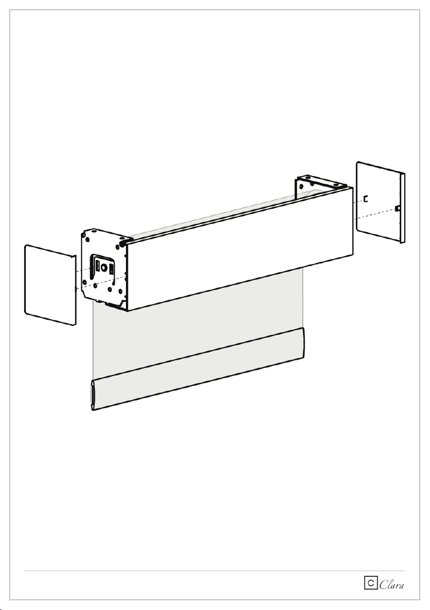
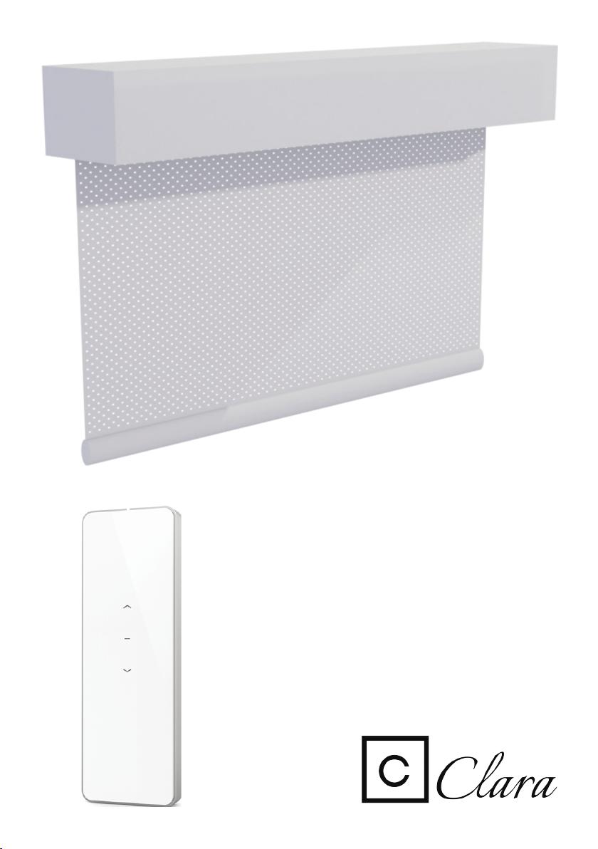
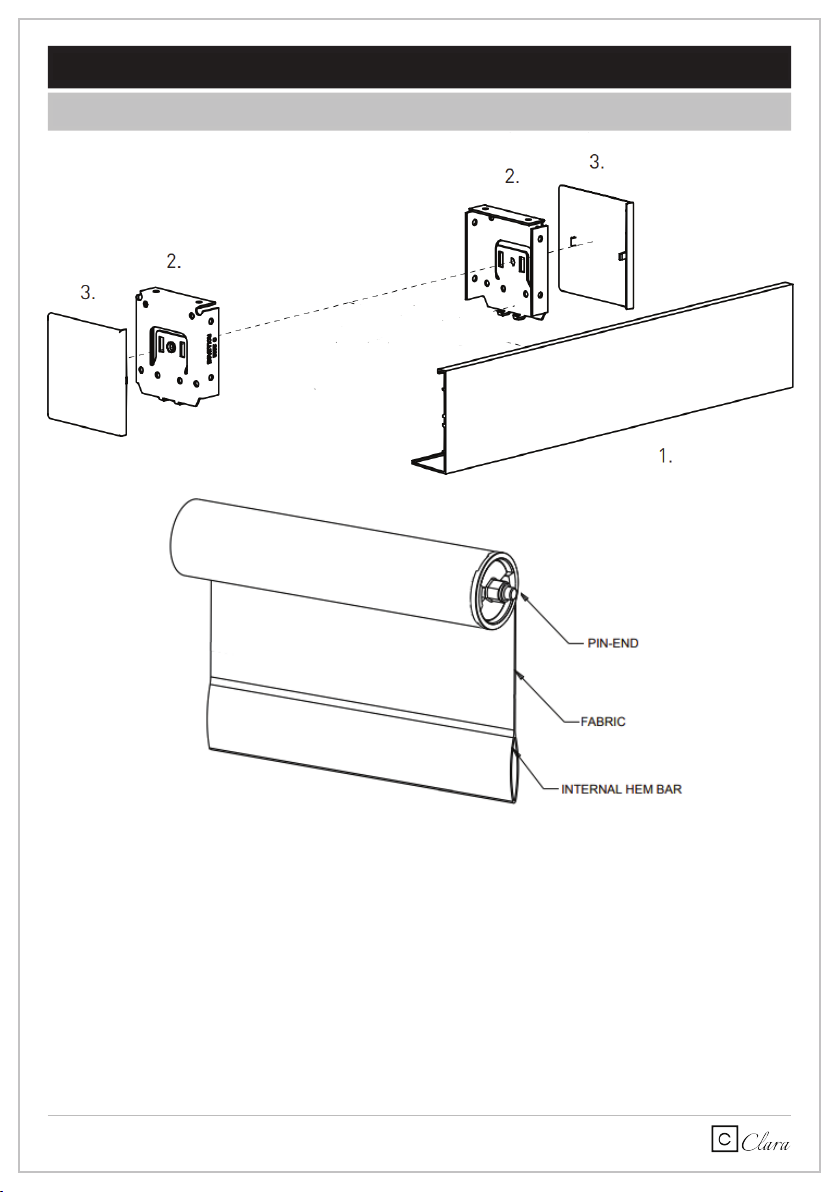
1.1 Aperçu des composantes requises pour votre installation
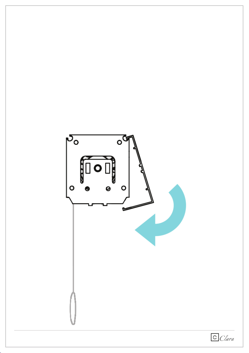
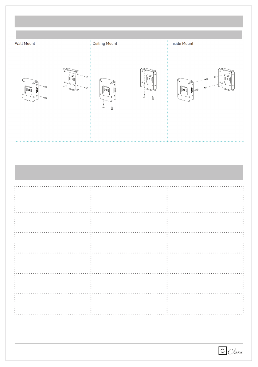
1.2 Guide d’installation
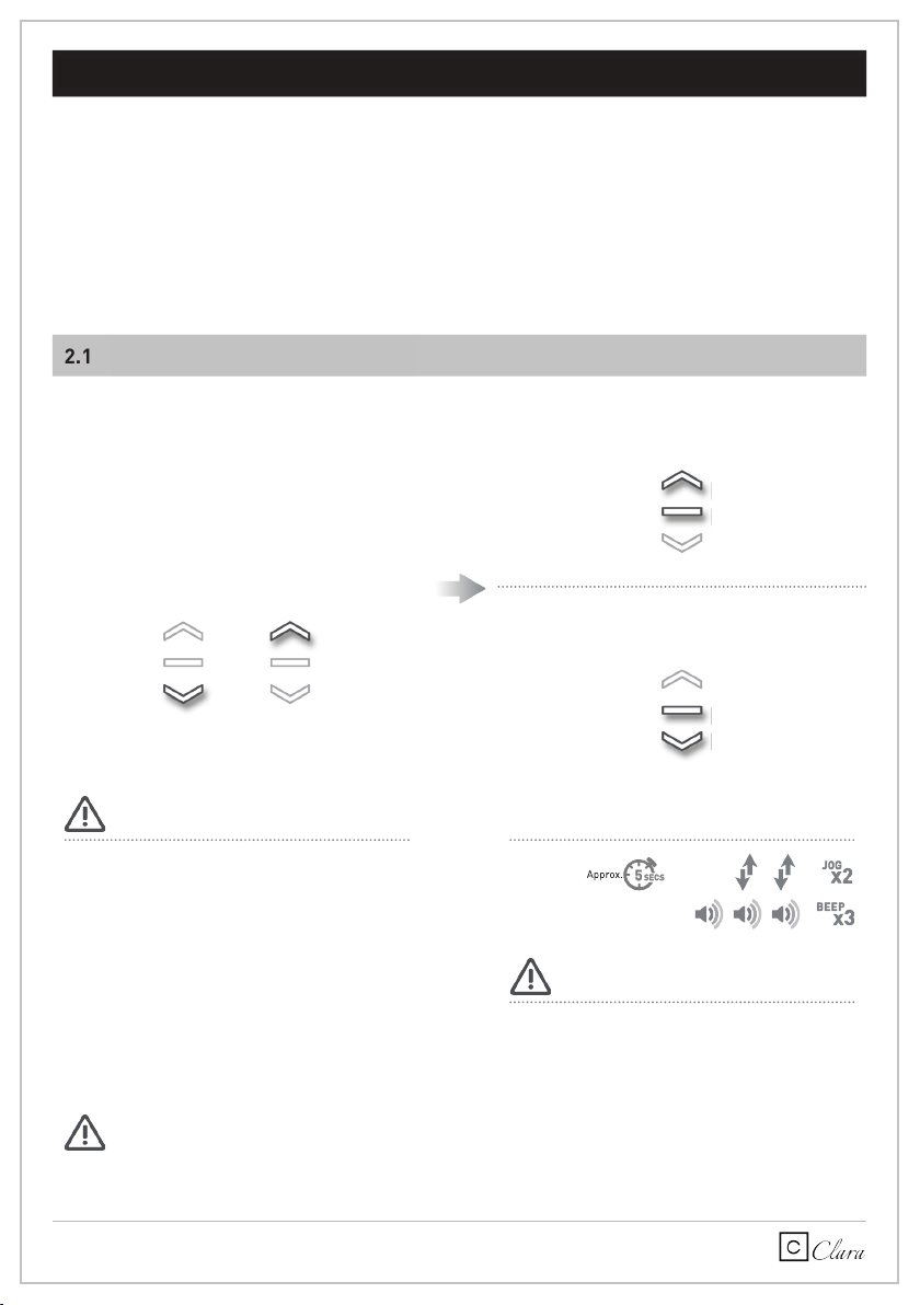
2.1 Programmation des limites
3.1 Déterminer L’état du moteur
3.2 Les options de configuration du moteur
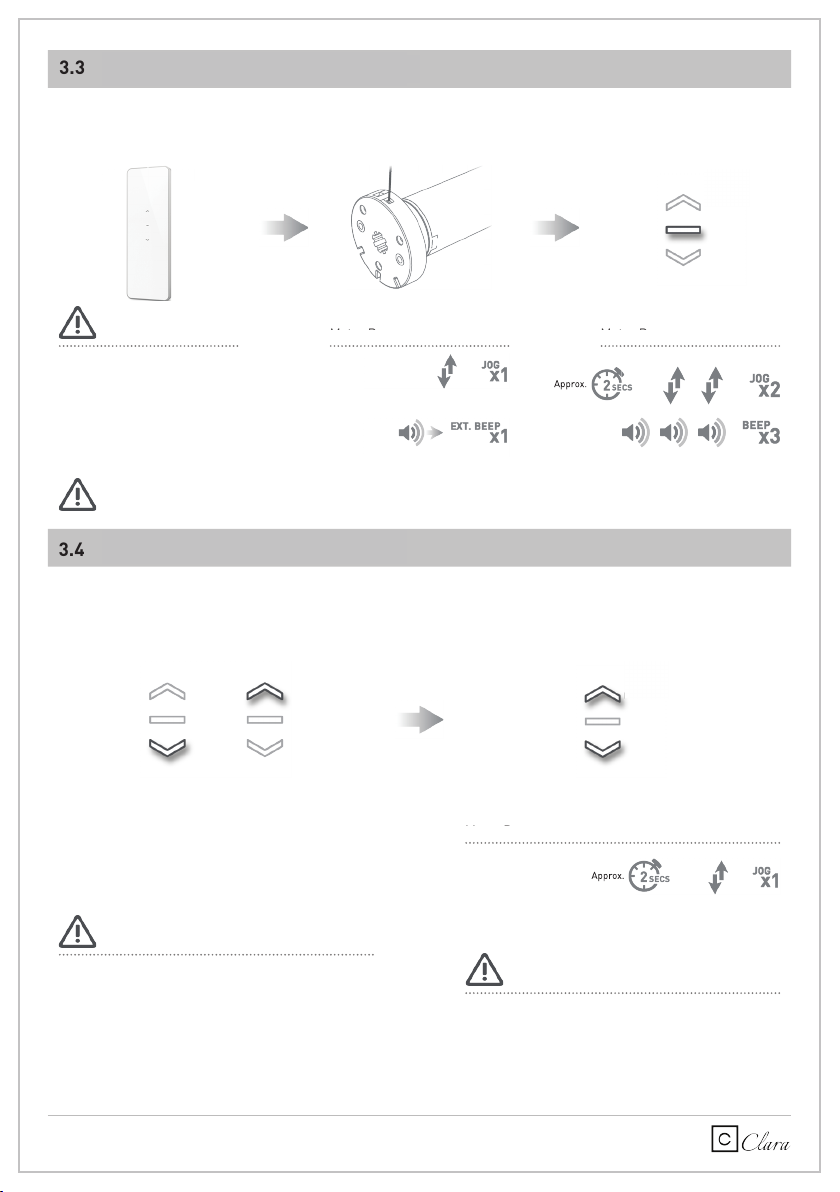
3.3 Appairage de la télécommande
3.4 Vérifier la direction du moteur
1 INSTALLATION DE VOTRE TOILE
3
4
7
8
8
9
9
3
2 PROGRAMMATION RAPIDE
3 PROGRAMMATION AVANCÉE
7
8
3 | Automate Programming Instructions | DC Tubular Motors ROLLEASE ACMEDA
Table des matières
1ASSEMBLY 5
2WIRING 6
2.1 Power options 6
2P1 BUTTON FUNCTIONS 7
3INTIAL SET-UP 8
8
8
3.1 Pair motor with controller
3.2 Check motor direction
3.3 Set limits 9
4ADJUSTING LIMITS 10
10
4.1 Adjust upper limit
4.2 Adjust lower limit 10
5ADDING OR REMOVING CONTROLLERS AND CHANNELS 11
11
5.1 Using motor P1 button
5.2 Using a pre-existing controller 11
6FAVORITE POSITIONING 12
12
12
12
13
6.1 Set a favorite position
6.2 Send shade to favorite position
6.3 Delete favorite position
7ADJUSTING MOTOR SPEED
7.1 Increase or decrease motor speed 13
8TILT & ROLLER MODE 14
14
14
14
8.1 Enter tilt mode
8.2 Enter roller mode (Default)
9SLEEP MODE
9TROUBLESHOOTING 15
TABLE DES MATIÈRES
3 | Automate Programming Instructions | DC Tubular Motors ROLLEASE ACMEDA
Table des matières
1ASSEMBLY 5
2WIRING 6
2.1 Power options 6
2 P1 BUTTON FUNCTIONS 7
3INTIAL SET-UP 8
8
8
3.1 Pair motor with controller
3.2 Check motor direction
3.3 Set limits 9
4ADJUSTING LIMITS 10
10
4.1 Adjust upper limit
4.2 Adjust lower limit 10
5ADDING OR REMOVING CONTROLLERS AND CHANNELS 11
11
5.1 Using motor P1 button
5.2 Using a pre-existing controller 11
6FAVORITE POSITIONING 12
12
12
12
13
6.1 Set a favorite position
6.2 Send shade to favorite position
6.3 Delete favorite position
7ADJUSTING MOTOR SPEED
7.1 Increase or decrease motor speed 13
8TILT & ROLLER MODE 14
14
14
14
8.1 Enter tilt mode
8.2 Enter roller mode (Default)
9SLEEP MODE
9TROUBLESHOOTING 15
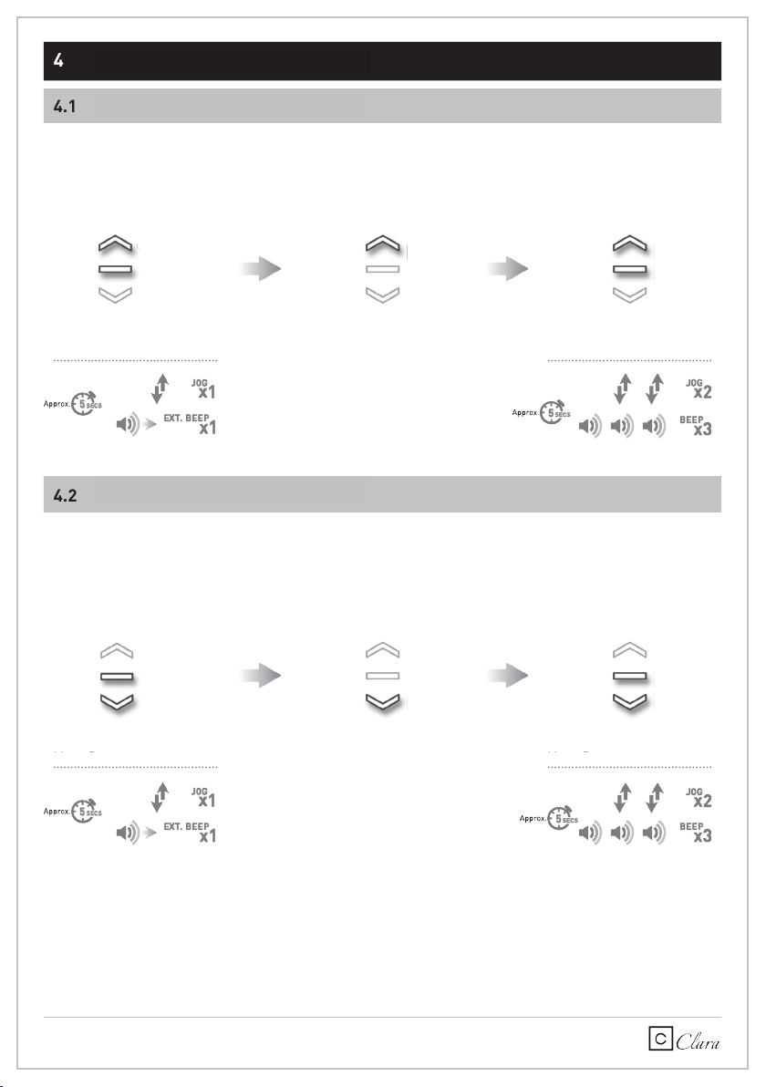
4.1 Limite supérieure de la toile
4.2 Limite inférieure de la toile
5.1 Établir l’état du moteur à l’aide du bouton P1
5.2 Utilisation d’une télécommande existante
6.1 Ajout d’une position favorite à la toile
6.2 Comment envoyer la toile à la position favorite
6.3 Supprimer la position favorite
7.1 Accélération ou ralentissement de la vitesse
10
10
11
11
12
12
12
13
4 AJUSTEMENT DES LIMITES DE LA TOILE
5 AJOUT ET SUPPRESSION DE TÉLÉCOMMANDE OU CANAUX
6 POSITION FAVORITE DE LA TOILE
7 AJUSTEMENT DE LA VITESSE DU MOTEUR DE VOTRE TOILE
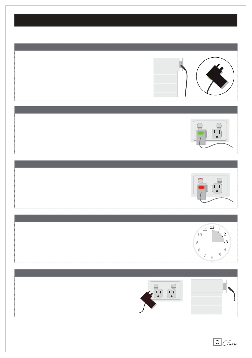
8 COMMENT RECHARGER LA BATTERIE DU MOTEUR
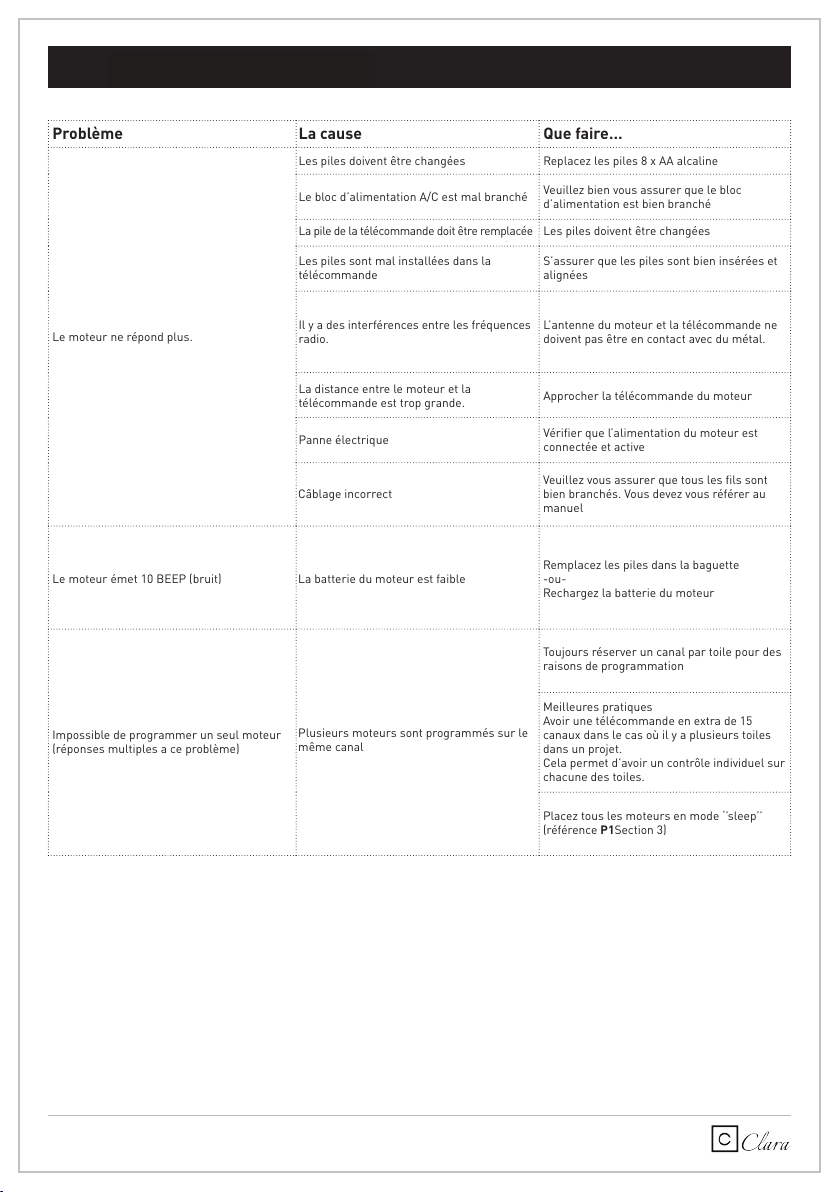
9 TROUSSE DE DÉPANNAGE
10
11
12
13
14
15