Clarinox Koala EVM Instruction manual

Clarinox Technologies Pty. Ltd.
ABN 89 062 954 170
28 / 296 Bay Rd
Cheltenham VIC 3192
Tel (613) 9095 8088
www.clarinox.com
Koala EVM
Quick Start Manual
The information contained herein shall not be disclosed to unauthorized persons. This document remains the
property of Clarinox Technologies Pty Ltd. It contains proprietary and confidential information and is considered to
be a trade secret by Clarinox Technologies Pty Ltd. No information contained herein is to be shared, copied,
disclosed, or otherwise compromised in any waywithout the written consent of Clarinox Technologies Pty Ltd. The
contents of this document are subject to change without notice. ClarinoxTechnologies Pty Ltd reserves the right
to make changes in this document as progress in planning, development, engineering or manufacturing warrants.
All Rights Reserved, Copyright Clarinox Technologies Pty Ltd © 2001-2014
Revision History
Edit
Date
Design
Approval
Description
01
22 January 2014
JZ
GT
Initial draft
02
17 July 2014
JZ
GT
Update formatting, layout, descriptions

Quick Start Manual
Page 2
Table of Contents
1Introduction ................................................................................................................................................4
1.1 Purpose .................................................................................................................................................4
1.2 System Requirements............................................................................................................................4
1.3 Supported Development Tool Chains .....................................................................................................4
2Getting started............................................................................................................................................5
3Configuring the Koala EVM Hardware.........................................................................................................7
3.1 CAN Bus Termination.............................................................................................................................7
3.2 USART2 / FSMC (LCD) Selection ..........................................................................................................7
4ST-LINK Configuration: Programming / Debugging the Koala EVM.............................................................7
5Wireless Module Interfaces.........................................................................................................................8
5.1 Connecting Modules...............................................................................................................................8
5.2 Hardware interface.................................................................................................................................8
6Brief Description of Key Peripherals..........................................................................................................10
7Instructions for Using Demo Application Binaries ......................................................................................11
7.1 Programming Binaries Using ST-LINK..................................................................................................11
7.2 USB to Serial example (printf) ..............................................................................................................11
7.3 IAP Ethernet example ..........................................................................................................................12
7.4 Ethernet to UART Application...............................................................................................................12
7.5 USB HID Device Example....................................................................................................................12

Quick Start Manual
Page 3
List of Figures
No table of figures entries found.

Quick Start Manual
Page 4
1 Introduction
This document describes beginning development for the Koala EVM board with the
STM32F407IGT6/STM32F429IIT6 microcontroller.
1.1 Purpose
The purpose of this document is to discuss how to use the Clarinox Koala EVM, and WMI Wi-Fi and/or Bluetooth
modules. This document will lead the user through required steps for hardware and software setup and the
debugging of applications.
1.2 System Requirements
Windows 7 or later
2 x USB mini cable for JTAG and debug output
Optional peripherals include LCD module, camera module and micro USB cable
1.3 Supported Development Tool Chains
IAR EWARM
Keil MDK-ARM

Quick Start Manual
Page 5
2 Getting started
Figure 1: Koala EVM PCB Layout
1. The Koala EVM must be supplied with 5v power. Power can be supplied with a 5v DC adapter via CN20
screw terminal or CN18 barrel connector, or via USB by connecting CN11 mini USB port to a standard
COM port of the PC.
2. To program the board:
i. connect CN11 mini USB port to a PC,
ii. configure the tool chain to use ST-LINK JTAG, and
iii. connect appropriate jumpers from ST-LINK to programming target (main MCU or WMI module).
3. Use the provided demo applications for test and development.
4. Connect any additional project accessories (LCD, camera, wireless modules, USB or Ethernet cables)
5. Download and run the software applications using the preferred tool-chain.

Quick Start Manual
Page 6
Figure 2: Populated Koala EVM Board

Quick Start Manual
Page 7
3 Configuring the Koala EVM Hardware
The Koala EVM hardware is configured by setting on board jumpers.
3.1 CAN Bus Termination
For high speed or long distance transmission, it is recommended to enable the CAN termination resistor. This is
done by shorting J2 pins.
Figure 3: Jumpers shorting J2 pins –enables CAN termination resistor
3.2 USART2 / FSMC (LCD) Selection
A UART peripheral and the LCD controller share a data line on the Koala EVM, and the required function must be
selected accordingly.
If any of the WMI modules require access to USART2, then CN21 pins 1-2 must be connected.
Figure 4: Jumpers shorting CN21 pins 1-2 –enables USART2
To enable LCD functionality, CN21 pins 2-3 must be connected.
Figure 5: Jumpers shorting CN21 pins 2-3 –enables LCD functionality
4 ST-LINK Configuration: Programming / Debugging the
Koala EVM
The embedded ST-LINK can be used to program the on board microcontroller and debug applications. Configure
the jumpers as shown below to enable ST-LINK program/debug.
Figure 6: Jumpers between CN13 and CN14 pins –selects STM32F407IGT6/STM32F429IIT6 MCU to
program/debug
For further information, consult the Koala EVM user manual or STMicroelectronics documentation

Quick Start Manual
Page 8
5 Wireless Module Interfaces
5.1 Connecting Modules
The Koala EVM features a 100 pin COM8 socket for connecting Wi-Fi / Bluetooth modules. The connector is
marked “COM8” and is notched. Position of the notch must be observed to avoid damaging the module.
Figure 7: COM8 connector. The notch is located on the bottom-right corner of the connector.
Clarinox WMI modules may also be connected to the Koala EVM with the dedicated WMI connectors. The WMI
module is to be inserted in both connectors, observing the notches for correct placement of the module.
Figure 8: WMI connector
5.2 Hardware interface
When connecting a module to the COM8 connector, the following methods are to be used for interfacing with the
STM32F407IGT6/STM32F429IIT6 Microcontroller.
WLAN communications are through SDIO interface, as shown in the following diagram.

Quick Start Manual
Page 9
Figure 9: Wi-Fi communication hardware layout and signals
Bluetooth HCI is connected to USART6 of the microcontroller. Cross connection of TX/RX and RTS/CTS lines
must be observed according to the following diagram.
Figure 10: Bluetooth communications hardware layout and signals
Bluetooth and Wi-Fi both have their own select/enable line. An interrupt line is also provided for Wi-Fi.
The Koala EVM board provides level translation and slow clock for interfacing to the attached COM8 module.
Output to ClarinoxDebugger is provided through USART2 of the microcontroller. ClarinoxDebugger is a powerful
GUI tool for remotely debugging ClarinoxSoftFrame-based applications. For more information on the debugger,
refer to the ClarinoxDebugger user manual.
MCU WL module
SDIO_D0:3
WL_EN
WL_IRQ
SDIO_CMD
SDIO_CLK
Slow Clock
32.768 kHz
1.8v regulator
VIO
3.3v supply
Vbat
Voltage Translator
MCU BT module
Rx
BT_EN
Slow Clock
32.768 kHz
1.8v regulator
VIO
3.3v supply
Vbat
Tx
Rx
Tx
RTS
RTS
CTS
CTS
Voltage Translator
Quick Start Manual
Page 10
6 Brief Description of Key Peripherals
Power supply
The Koala EVM is powered by USB or external supply (5v). The board features both a screw terminal (CN20) and
barrel connector (CN18) for external power supply of 5v to supply on board regulators and USB-OTG VBUS.
Regulators provide 3.3v for MCU and peripherals and 1.8v for wireless module.
5v and 3.3v are supplied to WMI connector.
USB
The Koala EVM supports USB-OTG HS. The USB micro connector (CN2) allows the user to connect to a host or
peripheral device in full speed operation without a PC.
A USB mini connector (CN9) is also featured which enables direct communication with a PC by converting USB to
serial (USART).
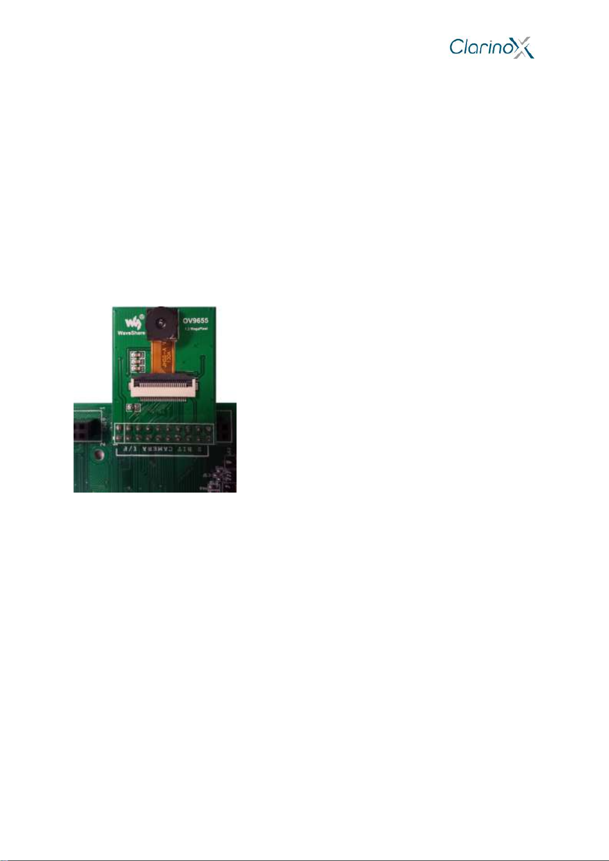
Camera interface
The Koala EVM features a digital camera interface (DCMI connector) to acquire images from a camera accessory.
Single frame or continuous capture is supported in an 8 to 12 bit parallel interface. Crop and several image formats
are also supported by the MCU.
The DCMI interface is most compatible with OV9655 cameras.
Figure 11: OV9655 camera connected to DCMI port
LCD Interface
The Koala EVM Board includes an interface for a LCD module with touch screen.
Display is controlled through the FSMC interface. Touch screen data is read through SPI interface and GPIOs are
used for touch screen interrupts.
The connector assumes a LCD controller IC is built into the LCD module.
To use the LCD, a jumper must be placed across CN21 pins 2 and 3, as illustrated in Figure 5.
CAN Bus
The Koala EVM utilizes a driver (SN65HVD230) to interface to anexternal CAN Bus.This allowsthe MCU to create
a node on the bus and communicate with other peripherals in an automotive setting.
Ethernet
The Koala EVM features an Ethernet interface and physical layer (DP83848I), allowing it to connect to a wired
network for communicating with other LAN devices.

Quick Start Manual
Page 11
7 Instructions for Using Demo Application Binaries
The following software required for PC
STM32 ST-LINK Utility program
Figure 12: STM32 ST-LINK Utility application
ST-LINK driver
Silicon Labs CP120x driver (USB to UART serial bridge)
Terminal emulation software with support for telnet and serial port connections (Tera Term, Putty,
HyperTerminal are suitable options)
7.1 Programming Binaries Using ST-LINK
1. Ensure jumpers on Koala EVM are installed. Required jumper installation is illustrated in Figure 6;
jumpers between CN13 and CN14 pins selects MCU to program/debug.
2. Connect CN11 (DEBUG) mini USB port to PC using USB mini cable. Note, the ST-LINK driver must be
installed for the board to be successfully recognised.
3. Open the STM32 ST-LINK Utility program:
i. connect to the target board (Target menu Connect)
ii. perform a full erase of the Flash memory (Target menu Erase Chip or CTRL+E)
iii. open the binary or hex file for the example project (File menu Open file or CTRL+O)
iv. write the binary or hex file to the Flash memory (Target menu Program and Verify or
CTRL+P)
v. disconnect the board (Target menu Disconnect or CTRL+D)
4. Reset the Koala EVM. The RESET button (SW1) is located near the USB-Serial connector.
7.2 USB to Serial example (printf)
Silicon Labs CP120X PC driver may be required for USB-UART peripheral.
1. Connect USB-Serial to PC with a second USB mini cable. The Debug cable is required for programming
the binary with ST-LINK and for power if an external power supply is not in use.
2. Program the USB to Serial example binary using STM32 ST-LINK Utility
3. Open a serial port console (Tera Term, Putty, HyperTerminal):
select the USB serial port (COM1, COM2, …)
Quick Start Manual
Page 12
configure settings: 921600 baud rate, 8 bit data, no parity, 1 stop bit, no flow control
The Koala EVM will display characters from the terminal.
7.3 IAP Ethernet example
1. Connect the Koala EVM to an Ethernet network
2. Program the IAP Ethernet example binary using STM32 ST-LINK Utility
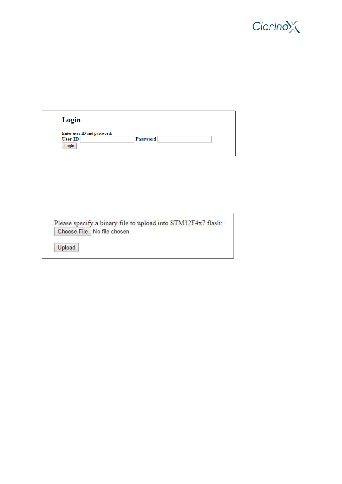
Enter the IP address “192.168.0.243”in a web browser. This should open the IAP application demo website.
Figure 13: IAP application demo website with simple login form
Credentials are required to access the server:
User ID: “user”
Password: “stm32”
This will open a webpage with the option to upload a binary file into Flash memory of MCU.
Figure 14: Successful login grants user the option to upload binary file into Flash memory
7.4 Ethernet to UART Application
Silicon Labs CP120X PC driver may be required for USB-UART peripheral.
1. Connect USB-Serial to PC with a second USB mini cable. Debug cable is required for programming the
binary with ST-LINK and for power if an external power supply is not in use.
2. Program the Ethernet to UART example binary using STM32 ST-LINK Utility
3. Open a serial port console:
select the USB serial port (COM1, COM2, …)
configure settings: 921600 baud rate, 8 bit data, no parity, 1 stop bit, no flow control
4. Connect the Koala EVM to an Ethernet network and connect to it via TCP
5. Open a telnet console and connect to TCP 192.168.0.243, port 8080 or enter 192.168.0.243:8080 in a
web browser.
Any characters from the network should appear in the serial console.
7.5 USB HID Device Example
1. Connect the Koala EVM to PC with USB micro cable from CN2 (USB-OTG connector)
2. Program the USB HID Device example binary using STM32 ST-LINK Utility
The PC cursor should move in a straight direction.
Table of contents


