Elnec BeeHive8S User manual
User's Manual for
BeeHive8S
Fast universal 8x 48-pindrive Stand-Alone concurrent multiprogramming system
ELNEC s.r.o.
Presov, Slovakia
March 2009

ELNEC s.r.o.
This document is copyrighted by ELNEC s.r.o., Presov, Slovakia. All rights reserved.
This document or any part of it may not be copied, reproduced or translated in any form
or in any way without the prior written permission of ELNEC s.r.o.
The control program is copyright ELNEC s.r.o., Presov, Slovakia. The control program
or any part of it may not be analyzed, disassembled or modified in any form, on any
medium, for any purpose.
Information provided in this manual is intended to be accurate at the moment of release,
but we continuously improve all our products. Please consult manual on
www.elnec.com.
ELNEC s.r.o. assumes no responsibility for misuse of this manual.
ELNEC s.r.o. reserves the right to make changes or improvements to the product
described in this manual at any time without notice. This manual contains names of
companies, software products, etc., which may be trademarks of their respective
owners. ELNEC s.r.o. respects those trademarks.
COPYRIGHT ©1997 - 2009
ELNEC s.r.o.
ZLI-0307B
2

ELNEC s.r.o.
Table of contents
Introduction .............................................................................................................................. 4
BeeHive8S elements ............................................................................................................. 7
Manipulation with the programmed device ............................................................................ 8
In-system serial programming by BeeHive8S........................................................................ 8
Selftest and calibration check ................................................................................................ 9
Technical specification.........................................................................................................11
Programming a device........................................................................................................... 16
Engineering mode................................................................................................................16
Production mode.................................................................................................................. 20
Software .................................................................................................................................. 23
Detailed description of Graphics user interface with touch screen ...................................... 23
Administration of build in PC................................................................................................ 39
Troubleshooting and warranty.............................................................................................. 43
Troubleshooting ................................................................................................................... 43
If you have an unsupported target device............................................................................ 44
Maintenance ........................................................................................................................ 44
Warranty terms .................................................................................................................... 45
Please, download actual version of manual from
ELNEC WEB site (www.elnec.com), if current one
will be out of date.
Conventions used in the manual
References to the control program functions are in bold, e.g. Load, File, Device, etc.
References to control keys are written in brackets <>, e.g. <F1>.
Terminology used in the manual:
Device any kind of programmable integrated circuits or programmable
devices
ZIF socket Zero Insertion Force socket used for insertion of target device
Buffer part of memory or disk, used for temporary data storage
USB port type of PC port
HEX data format format of data file, which may be read with standard text viewers;
e.g. byte 5AH is stored as characters '5' and 'A', which mean
bytes 35H and 41H. One line of this HEX file (one record) contains
start address and data bytes. All records are secured with
checksum.
3
ELNEC s.r.o.
Introduction
BeeHive8S is extremely fast universal 8x 48-pindrive Stand-Alone concurrent
multiprogramming system designed for high volume production programming with
minimal operator effort. The chips are programmed at near theoretical maximum
programming speed.
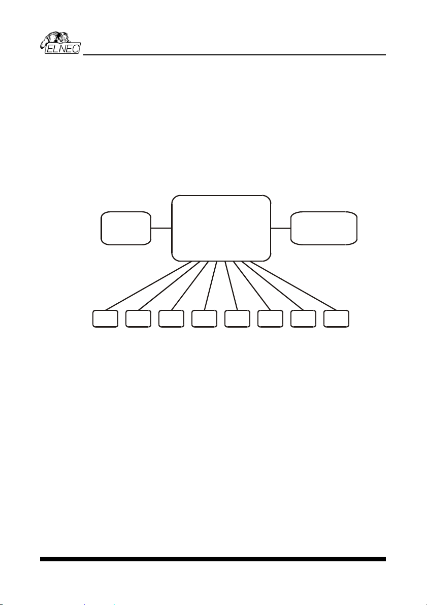
Block scheme of BeeHive8S
site 1 site 8
Windows XP Embedded
driven
high performance PC
graphics control unit
with touch screen
external display
keyboard
mouse
site 2 site 3 site 4 site 5 site 6 site 7
optional
BeeHive8S consists of eight independent isolated universal programming modules,
based on the BeeProg+ programmer hardware. Therefore BeeHive8S sockets can run
asynchronously (concurrent programming mode). Each programming module starts
programming at the moment the chip is detected to be inserted in the socket properly -
independently of the status of other programming modules. This results in seven
programming modules working while you replace the programmed chip in the eighth.
Graphical control unit with touch screen provides basic control and easy monitoring of
the programming flow.
Modular construction of hardware - the programming modules work independently -
allows for continuing operation when a part of the circuit becomes inoperable. It also
makes service quick and easy.
Hands-free operation: asynchronous and concurrent operation allows a chip to begin
programming immediately upon insertion of a chip. The operator merely removes the
finished chip and inserts a new chip. Operator training is therefore minimized.
BeeHive8S supports all kinds and types of silicon technology found in today’s and
tomorrows programmable devices without family specific modules. You can be sure that
new device support requires the software to be updated and (if necessary) simple
4

ELNEC s.r.o.
package converter (programming adapter), therefore the ownership costs are
minimized.
Using built-in in-circuit serial programming (ISP) connector, the programmer is able to
program ISP capable chips in circuit.
BeeHive8S provides very competitive price coupled with excellent hardware design for
reliable programming. It has probably best "value for money" programmer in this class.
BeeHive8S provides very fast programming due to high-speed FPGA driven hardware
and execution of time-critical routines inside of the programmer. At least programming
speed is faster than competitors in this category, for many chips it is much faster than
most competitors. As a result, when used in production this programmer waits for an
operator, and not the other way round.
BeeHive8S provides the two banana jacks, one for ESD wrist strap connection for
easy-to-implement ESD protection and the second one for connection to ground.
FPGA based totally reconfigurable 48 powerful TTL pindrivers provide
H/L/pull_up/pull_down and read capability for each pin. Advanced pindrivers incorporate
high-quality high-speed circuitry to deliver signals without overshoot or ground bounce
for all supported devices. Pin drivers operate down to 1.8V so you'll be ready to
program the full range of today's advanced low-voltage devices.
BeeHive8S performs on each programming module device insertion test (wrong or
backward position) and contact check (poor contact pin-to-socket) before it programs
each device. These capabilities, supported by overcurrent protection and signature-
byte check help prevent chip damage due to operator error.
BeeHive8S has the selftest capability, which allows the diagnostic part of software to
thoroughly check the health of the each programming module.
BeeHive8S has a built-in protection circuit for eliminating the damage of programmer
and/or programmed device due to environment or operator failure. All ZIF socket pins of
BeeHive8S programmer are protected against ESD up to 15kV.
BeeHive8S performs programming verification at the marginal level of supply voltage,
which, obviously, improves programming yield, and guarantees long data retention.
Various socket converters are available to handle devices in PLCC, SOIC, PSOP,
SSOP, TSOP, TSSOP, TQFP, QFN (MLF), SDIP, BGA and other packages.
It is important to remember that in most cases new devices require only a software
update because the BeeHive8S is based on the truly universal (BeeProg+)
programmer. With our prompt service you can have new device added to the list of
supported devices within hours! See AlgOR (Algorithm On Request) service for details.
Advanced design of the BeeHive8S Stand-Alone multiprogramming system, including
protective circuits, original brand components, and careful manufacturing and long
burning-in periods allows us to provide a three-year warranty on parts and labor for the
programmer (limited 25 000-cycle warranty on ZIF sockets). Although we take as much
care as possible to integrate high quality components for the built-in computer, we can't
5
ELNEC s.r.o.
provide the same level warranty as we get from the suppliers of computer parts.
Therefore it is a limited warranty of one year for all computer parts such as
motherboard, CPU, HD, etc.
This warranty terms are valid for customers, who purchase a programmer directly from
Elnec company. The warranty conditions of Elnec sellers may differ depending on the
target country law system or Elnec seller’s warranty policy.
Free additional services:
•free lifetime software update via Web site.
Free software updates are available from our
Internet address www.elnec.com.
•Online technical support is available within promised 24 hours time limit or you may
call us during business hours from Monday through Friday 8:30 to 17:30 (CET).
•Keep-Current is a service by which ELNEC ships to you the latest version of the
control program for programmer and the updated user documentation. A Keep-
Current service is your hassle-free guarantee that you always have access to the
latest software and documentation, at minimal cost.
•AlgOR (Algorithm On Request) service allows you to receive from ELNEC software
support for programming devices not yet available in the current device list.
6

ELNEC s.r.o.
BeeHive8S elements
1) 48 pin ZIF socket
2) work result LEDs
3) power/sleep LED of site
4) YES! Button
5) ISP connector
6) graphical control unit with touch screen
7) fan's grid
8) temperature controlled fans
9) banana jack for connection to ground
10) banana jack for ESD wrist straps connection
11) Windows XP Embedded serial number sticker
7

ELNEC s.r.o.
12) PC connectors – e.g. for display, keyboard, mouse…
13) power switch
14) power supply connector
15) Soft power ON/OFF button
Manipulation with the programmed device
After the selection of desired device for your work, you can insert it into the open ZIF
socket (lever is up) and close socket (lever is down). The correct orientation of the
IF socket on the programmer
e socket when the BUSY LED
ectronics protect the target device and the programmer
failure.
due to
incorrect, user-selected programming parameters. Target device may not be destroyed
In-system serial programming by BeeHive8S
ISP
ction about ISP see section Common
Description of ISP connector
device in ZIF socket is shown on the picture near the Z
med device must be removed from thcover. The program
is off.
Note: Programmer protection el
itself against either short or long-term power failures and, partly, against a PC
However, it is not possible to guarantee the integrity of the target device
by forced interruption of the control program (turn off programmer), but the content of
programmed cells may remains undefined. Don't unplug the target device from the ZIF
socket during work with device (BUSY LED on).
Optimized advanced pindrivers deliver programming performance without overshoot or
ground bounce for all device technologies. Pin drivers operate down to 1.8V so you'll be
ready to program the full range of today's advanced low- voltage devices.
The ISP programming solution performs programming verification at the marginal level
of supply voltage, which, obviously, improves programming yield, and guarantees long
data retention.
The ISP programming solution provides also the power supply for the target system.
This ISP programming solution provides very competitive price but excellent hardware
design for reliable programming.
he software provides full information for ISP implementation: Description ofT
connector pins for currently selected chip, recommended target design around in-circuit
programmed chip and other relevant information.
or general definition, recommendation and direF
notes / ISP please.
13 5
2 4 6
79
8 10
11 13
12 14
15 17 19
16 18 20
Front view at ISP connector.
8

ELNEC s.r.o.
Specification of ISP connector pins depends on the device which you want to work with.
rogrammer (Pg4uw), menu Device / Device Info
g (ISP) option of respective device must be
selected. It is indicated by (ISP) suffix after the name of selected device.
These specifications correspond with application notes published by device
manufacturers. Application notes can be found on www.elnec.com
You can find it in the control SW for p
(Ctrl+F1). Note the ISP programmin
,section Support /
Application Notes.
Note: Pin no. 1 is signed by t necto s.riangle mark on ISP cable con r
BeeHive8S ISP cable
Warnings:
•Use only ISP cable from delivery package. When you use other ISP cable (other
material, length…), programming may become unreliable.
•BeeHive8S can supply power to the programmed device (pin 1 of ISP connector)
and the target system (pin 19 and 20 of ISP connector) with some limitations (see
Technical specification / ISP connector).
•BeeHive8S applies programming voltage to target device and checks its value
(target system can modify programming voltage). If the programming voltage is
different from expected, no action with target device will be executed.
d driverNote: H/L/rea
R1
H/L driver
in programmer pin of ISP
connector
read driver
in programmer
R2
PU/PD driver
in programmer
R3
R1=180R R2=1k3 R3=22k
Selftest and calibration check
Warning:
Selftest and calibration check can be run in engineering mode only.
This mode is available only when external display, keyboard and mouse are connected
to BeeHive8S.
9
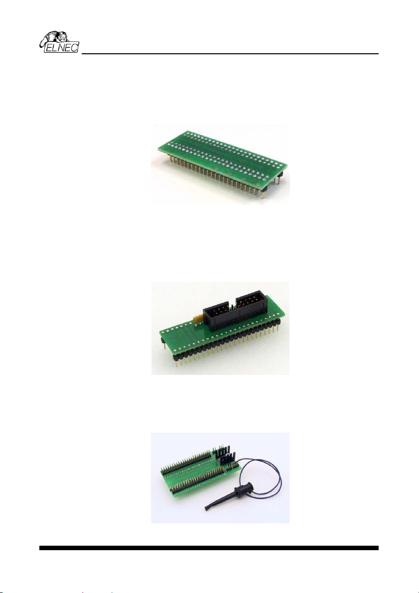
ELNEC s.r.o.
If you feel that y tion, please
iagnostic POD (Diagnostic POD
y package.
pin diagnostic POD - type I into ZIF socket of the programmer. Take care
of POD).
our programmer does not react according to your expecta
run the programmer (ISP connector’s) selftest using D
for ISP connectors #2), enclosed in the standard deliver
Selftest of programmer
•Insert 48
about orientation of 48 pin diagnostic POD - type I (see top side
•Run selftest of programmer in PG4UW (Programmer / Selftest plus).
Se
•Insert Diagnostic POD for ISP connectors #2 into ZIF socket of the programmer.
Take care about orientation of Diagnostic POD for ISP connectors #2.
•Interconnect the 20 pins connector of Diagnostic POD for ISP connectors #2 with
the ISP connector of the programmer with the ISP cable included in delivery with the
programmer package. Be sure that the pins are interconnected properly (i.e. 1-1, 2-
2, ..., 20-20).
•Run selftest of ISP connector in PG4UW (Programmer / Selftest ISP connector…).
lftest of ISP connector
Calibration test
For optimal results with programmer we recommend you also undertake every 6 months
an extended test to check the calibration using 48 Pins Calibration test POD, Type I
(optional accessories, ord.no. 70-0438).
•Insert 48 Pins Calibration test POD, Type I into ZIF socket of the programmer.
•Run calibration test of programmer in PG4UW (Programmer / Calibration test).
10

ELNEC s.r.o.
Technical specification
Specification (BeeHive8S multiprogramming system)
•8x universal programming module (8x 48-pin DIL ZIF sockets and 8x ISP connector)
•operation result LEDs, LED power
•line power input 100-240VAC/60W max.
•banana jack for ESD wrist straps connection
•banana jack for connection to ground
e of programmer)
ystem
S programming module)
H
transfer rate
PGA based state machine
, VPP1, and VPP2, controllable rise and fall time
V/1A
nge 0..26V/1A
er
Insertion Force) socket accepts both 300/600 mil devices up to
s H, L, CLK, pull-up, pull-down on all pindriver pins
lectable from 1.8 V up to 26V
rrent shutdown, power failure shutdown
each pin of socket (IEC1000-4-2: 15kV air, 8kV contact)
n is tested before every programming operation
IS
s insertion lock
wn; level H selectable from 1.8V
Specification (PC system insid
•Microsoft Windows XP Embedded operation s
•PC Intel Core 2 Duo 2.4 GHz
•1024 MB RAM
•160 GB HDD
PECIFICATION (valid for each
ARDWARE
Base unit, DACs
•USB 2.0 high-speed compatible port, up to 480 Mbit/s
l microprocessor and F•on-board intelligence: powerfu
rters for VCCP•three D/A conve
•..8VCCP range 0
•VPP1, VPP2 ra
•autocalibration/selftest
•selftest capability
Socket, pindriv
•48-pin DIL ZIF (Zero
48-pin
•pindrivers: 48 universal
•VCCP / VPP1 / VPP2 can be connected to each pin
pin•perfect ground for each
•FPGA based TTL driver provide
level se•analog pindriver output
overcu•current limitation,
•ESD protection on
•continuity test: each pi
P connector
•20-pin male type with mis
•6 TTL pindrivers, provides H, L, CLK, pull-up, pull-do
ltage including) devices.up to 5V to handle all (low-vo
•1x VCCP voltage (range 2V..7V/100mA) , can be applied to two pins
11

ELNEC s.r.o.
•programmed chip voltage (VCCP) with both source/sink capability and voltage sense
kV contact)
, which indicate state of work result = LED OK and LED Error (active
max 0.8V)
DE
P
ries, with 8/16 bit data width
es,
•: 24Cxxx, 24Fxxx, 25Cxxx, 45Dxxx, 59Cxxx, 25Fxxx, 25Pxxx, 85xxx,
LVxx
rris, National, Philips/Signetics, Tesla, TI
x50 series
•
CS08, HCS12
xx, ST10xx, STR7xx series
eries
•Microcontrollers ZILOG: Z86/Z89xxx and Z8xxx series
•1x VPP voltage (range 2V..25V/50mA)
•target system supply voltage (range 2V..6V/250mA)
•ESD protection on each pin of ISP connector (IEC1000-4-2: 15kV air, 8
•two output signals
level: min 1.8V)
•input signal, switch YES! equivalent (active level:
VICE SUPPORT (valid for each programming module)
rogrammer
•EPROM: NMOS/CMOS, 2708, 27xxx and 27Cxxx series, with 8/16 bit data width, full
support for LV series
•EEPROM: NMOS/CMOS, 28xxx, 28Cxxx, 27EExxx se
•Flash EPROM: 28Fxxx, 29Cxxx, 29Fxxx, 29BVxxx, 29LVxxx, 29Wxxx, 49Fxxx seri
from 256Kbit to 32Mbit, with 8/16 bit data width, full support for LV series
Serial E(E)PROM
93Cxxx, NVM3060, MDAxxx series, full support for LV series
•Configuration (EE)PROM: XCFxxx, XC17xxxx, XC18Vxxx, EPCxxx, AT17xxx, 37
•1-Wire E(E)PROM: DS1xxx, DS2xxx
•PROM: AMD, Ha
•NV RAM: Dallas DSxxx, SGS/Inmos MKxxx, SIMTEK STKxxx, XICOR 2xxx, ZMD
U63x series
PLD: Altera: MAX 3000•A, MAX 7000A, MAX 7000B, MAX 7000S, MAX7000AE,MAX II
•PLD: Lattice: ispGAL22V10x, ispLSI1xxx, ispLSI1xxxEA, ispLSI2xxx, ispLSI2xxxA,
ispLSI2xxxE, ispLSI2xxxV, ispLSI2xxxVE, ispLSI2xxxVL, LC4xxxB/C/V/ZC, M4-xx/xx,
M4A3-xx/xx, M4A5-xx/xx, M4LV-xx/xx
•PLD: Xilinx: XC9500, XC9500XL, XC9500XV, CoolRunner XPLA3, CoolRunner-II
•other PLD: SPLD/CPLD series: AMI, Atmel, AMD-Vantis, Gould, Cypress, ICT, Lattice,
NS, Philips, STM, VLSI, TI
•Microcontrollers 48 series: 87x41, 87x42, 87x48, 87x49, 87
•Microcontrollers 51 series: 87xx, 87Cxxx, 87LVxx, 89Cxxx, 89Sxxx, 89LVxxx, all
manufacturers, Philips LPC series
Microcontrolle•rs Intel 196 series: 87C196 KB/KC/KD/KT/KR/...
•Microcontrollers Atmel AVR: AT90Sxxxx, ATtiny, ATmega series
•Microcontrollers Cypress: CY7Cxxxxx, CY8Cxxxxx
Microcontrollers ELAN: EM78Pxxx
•Microcontrollers MDT 1xxx and 2xxx series
•Microcontrollers Microchip PICmicro: PIC10xxx, PIC12xxx, PIC16xxx, PIC17Cxxx,
PIC18xxx, PIC24xxx, dsPIC series
•Microcontrollers Motorola (Freescale): 68HC05, 68HC08, 68HC11, H
series
•Microcontrollers Myson MTV2xx, 3xx, 4xx and 5xx series
Microcontrollers National: COP8xxx•series
•Microcontrollers NEC: uPD78xxx series
•Microcontrollers Novatek: NT68xxx series
•Xxxx seriesMicrocontrollers Scenix (Ubicom): S
•Microcontrollers SGS-Thomson: ST6xx, ST7
•Microcontrollers TI: MSP430 and MSC121x s
12

ELNEC s.r.o.
•Microcontrollers other: EM Microelectronic, Fujitsu, Goal Semiconductor, Hitachi,
Holtek, Princeton, Macronix, Winbond, Infineon(Siemens), NEC, Samsung, Toshiba, ...
•upported devices see actual Device list at www.elnec.com
Notes:
For all s
P
series, serial data
xxx, ATtiny, ATmega series
es
12xxx, PIC16xxx, PIC17xxx,
•
CS08, HCS12
eries, 89xxx series
•AG and BSL series), MSC12xxx series
ispLSI2xxxV,
/xx, M4LV-xx/xx, M4A3-xx/xx, M4A5-xx/xx,
•XV, CoolRunner XPLA3, CoolRunner-II
F see actual Device list at www.elnec.com
rogrammer, through ISP connector
•Serial E(E)PROM: IIC series, MW series, SPI series, KEELOQ
Flash, PLD configuration memories
•Microcontrollers Atmel: AT89Sxxx, AT90Sx
•Microcontrollers Cypress: CY8C2xxxx
•Microcontrollers Elan: EM78Pxxx, EM6xxx series
•Microcontrollers EM Microelectronic: 4 and 8 bit seri
•Microcontrollers Microchip PICmicro: PIC10xxx, PIC
PIC18xxx, PIC24xxx, dsPIC series
Microcontrollers Motorola/Freescale: HC11 series, HC908 series (both 5-wire, All-
wire), H
•Microcontrollers NEC: uPD7xxx series
•Microcontrollers Philips: LPC2xxx series, LPC s
•Microcontrollers Scenix (Ubicom): SXxxx series
Microcontrollers TI: MSP430 (both JT
•PLD: Lattice: ispGAL22xV10x, ispLSI1xxxEA, ispLSI2xxxE,
ispLSI2xxxVE, ispLSI2xxxVL, M4-xx
LC4xxxB/C/V/ZC
•Various PLD (also by JAM player/JTAG support):
•Altera: MAX 3000A, MAX 7000A, MAX 7000B, MAX 7000S, MAX 9000, MAX II
Xilinx: XC9500, XC9500XL, XC9500
Notes:
or all supported devices .
Pa
with universal adapters
Pr
Devic Time
ckage support
•support all devices in DIP with default socket
•package support includes DIP, SDIP, PLCC, JLCC, SOIC, SOP, PSOP, SSOP,
TSOP, TSOPII, TSSOP, QFP, PQFP, TQFP, VQFP, QFN (MLF), SON, BGA, EBGA,
FBGA, VFBGA, UBGA, FTBGA, LAP, CSP, SCSP etc.
•support devices in non-DIP packages up to 48 pins
•programmer is compatible with third-party adapters for non-DIP support
ogramming speed
e Size [bits] Operation
M50F 100000Hx8 (8 Mega) programming and verify 22 secW080 (parallel Flash)
M 400000Hx16 (64 Mega) programming and verify 57 secX28F640C3BT (parallel Flash)
K9F1G08U0M (par sh) 8400000Hx8 (1 Giga) programming and verify 229 secallel NAND Fla
AT45 ga) programming and verify 36 secD081 (serial Flash) 108000Hx8 (16 Me
AT89C51RD2 (microcontroller) 10000Hx8 programming and verify 15 sec
PIC18F452 (microcontroller) 4000Hx16 programming and verify 4 sec
C
gramming
e non-
blank data is programmed or are they use data with only a few 0 bits (FE, EF, etc.).
onditions: PG4UW version 2.39a
Notes:
pro•It is important to know, we always use random number patterns for
speed tests. Some of our competitors use a "sparse" pattern, where only som
13

ELNEC s.r.o.
This deceptive approach
plan to compare, ask alw
can "decrease" programming times considerably. If you
ays which pattern they use.
The programming speed de e PC speed only slightly.
y manufacture d
ware re available y s,
ern and version of software is available for
y chip su vailable nearly same day.
Devi
•s
nt of part name
based selection of EPROM/Flash EPROM
read, verify
SD-71
compressed binary variation of SVF files
st, reverse insertion check
•
mode (automatic start immediately after device insertion)
erialization modes (more types of incremental modes, from-file data, custom
mode
Buffer operations
lit
•
•
File load/sa
•
•a entification/recognition
•pends on th
SOFTWARE
•Algorithms: onl r approved or certifie algorithms are used.
•Algorithm updates: soft updates a regularly, approx. ever 4 week
free of charge (Int et down Dem
highly priorit pport and/or bugs fixes. A
load). On
•Main features: revision history, session logging, on-line help, device and algorithm
information
ce operations
tandard:
•intelligent device selection by device type, manufacturer or fragme
•automatic ID-
•blank check,
•program
•erase
•configuration and security bit program
•illegal bit test
•checksum
•interpret the Jam Standard Test and Programming Language (STAPL), JEDEC
standard JE
•interpret the VME files
•security
•insertion te
•contact check
•ID byte check
special
•production
•lots of s
generator mode)
•statistics
•count-down
•view/edit,
•
find/replace
fill/copy, move, byte swap, word/dword sp
word)checksum (byte,
print
ve
no download time because programmer is PC controlled
utomatic file type id
14

ELNEC s.r.o.
Supported file formats
ry
OS, Exormax, Tektronix, ASCII-SPACE-
a POF, JEDEC (ver. 3.0.A), e.g. from ABEL, CUPL, PALASM, TANGO PLD,
D Designer ISDATA, etc.
TAPL Format), JBC (Jam STAPL Byte Code), STAPL (STAPL File)
•0V, 50-60Hz
•
•
•
•
•
Pac
essories
programmer
programmer (1x)
f the programmer (1x)
and banana plug
Ad
nt.
rt (phone/fax/e-mail).
ate via Web site.
•unformatted (raw) bina
•HEX: Intel, Intel EXT, Motorola S-record, M
HEX, ASCII HEX
•Alter
OrCAD PLD, PL
•JAM (JEDEC S
JEDEC standard JESD-71
•VME (ispVME file VME2.0/VME3.0)
GENERAL
operating voltage AC 100-24
power consumption max. 300W active
dimensions 625x465x115 mm (24.6x18.3x4.5 inch)
eight (programmerw ) 14.9kg (32.85 lbs)
temperature 5°C ÷ 35°C (41°F ÷ 95°F)
humidity 20%..80%, non condensing
age includedk
Standard acc
•BeeHive8S
•diagnostic POD for ZIF socket selftest of the
•st odiagnostic POD for ISP connector selfte
•ISP cable (8x)
•anti-dust cover for ZIF socket (8x)
•user manual
•software
•registration card
•calibration test report
•transport case
Bonus pack:
•ESD wrist strap with cord
•Vacuum pen
•Gift (surprise)
ditional services
•rreKeep Cu
•AlgOR
•free technical suppo
oftware upd•free lifetime s
15

ELNEC s.r.o.
Programmi
BeeHive8S can operate in two modes:
Engineering mode for creating a project
Production mode for mass production
Engineering mode
Warning:
This mode is available only when external display, keyboard and mouse are connected
to BeeHive8S.
To switch to Engineering mode use File / Switch to Engineering mode.
This part of the software is focused on the quick and easy preparation of the project file
for use in the production mode of the control software.
Each programming module is driven by an easy-to-use control program with pull-down
menu, hot keys and on-line help. Selecting of the device is performed by its class, by
manufacturer or simply by typing a fragment of vendor name and/or part number. It is
the same time proven software, as is used for all other Elnec single-site programmers.
Engineers can use all properties of this software and can make a project for mass
production.
Standard device-related commands (read, blank check, program, verify, erase) are
boosted by some test functions (insertion test, connection check, signature-byte check),
and some special functions (autoincrement, production mode - start immediately after
insertion of chip into socket).
All known data formats are supported. Automatic file format detection and conversion
are done during loading of file. It is possible to use Jam files (JEDEC standard JESD-
71) and VME files
The rich-featured auto-increment function enables one to assign individual serial
numbers to each programmed device - or simply increments a serial number, or the
function enables one to read serial numbers or any programmed device identification
signatures from a user created file.
The software also provides a lot of information about programmed device. As an
example, the drawings of all available packages, explanation of chip labeling (the
meaning of prefixes and suffixes on the chips).
ng a device
16

ELNEC s.r.o.
M
ogrammer.
ake a project
1. Connect external display, keyboard and mouse to PC connectors on back side of
programmer. Turn on pr
2. Run the control program: double click on icon.
3. Find BeeHive8S Site (programmer): <Ctrl+F> or right click on panel
Programmer
17

ELNEC s.r.o.
Select BeeHive8S, Site and then click on “Connect” button.
4. Select site.
Select desired BeeHive8S Site# and then click on “OK” button
5. Select device: click on icon and select desired device
6. Load data into buffer from file: click on icon.
7. Set Device operation options
18

ELNEC s.r.o.
Set desired operations for the device and then click on “OK” button
8. To customize device use menu <Alt+S>
Set desired settings for the device and en clickth on “OK” button
tions and <Alt+S> depend on the selected device.Note: Menu Device operation op
19

ELNEC s.r.o.
9. Save project: click on icon and select destination folder, write a description
of project etc.
You can make a project on other ELNEC programmers (BeeProg+…) too.
For more details see Help for PG4UW (single site driver) and “User manual for all
ELNEC programmers”.
The latest manual may be found at www.elnec.com part download.
Production mode
There are two modes:
Mode A: without external display, keyboard and mouse connected to BeeHive8S.
Programming control is only via build in display with touch screen.
Mode B: with external display, keyboard and mouse eeHive8S.
ay.
Warning: External display, keyboard and mouse not needed in this mode.
This part of the software is focused on the easy monitoring of high-volume production
operations via graphical control unit with touch screen.
The user can control the following basic operations:
•load project file
•connect/disconnect programmer sites
•select desired device master operation (blank check, verify, program, erase)
•start/stop device operation on connected programmer sites
•set some advanced options to customize available settings, for example Automatic
YES! Function
•create Job report
•create Problem report
•copy project file(s) from external drive (for example from network drive, USB key
etc.) to the standalone's local [Projects] folder
•see the progress of device operation, including statistics information, serialization...
Step by step instruction
Starting Stand-Alone multiprogramming system
1. Check if the power switch placed at back side of programmer, near power supply
connector is on position '0'.
2. Plug the power cord in to the programmer power supply connector and turn on
the programmer by the power switch placed at back side of programmer. If
programmer not starts (cooling fans not start) please, push the “Soft power
ON/OFF” button on back side, bellow banana jacks.
connected to B
Programming control is via Pg4uwMC displayed on external displ
20
Table of contents
Other Elnec Motherboard manuals

Elnec
Elnec BeeHive208S User manual

Elnec
Elnec JetProg User manual

Elnec
Elnec BeeProg2 User manual

Elnec
Elnec BeeHive204 User manual

Elnec
Elnec MEMprog2 User manual

Elnec
Elnec DATAMAN-48PRO2 User manual

Elnec
Elnec BeeHive304 User manual

Elnec
Elnec BeeHive204AP User manual

Elnec
Elnec BeeHive208S Administrator Guide


