Risecom Corporation R860 User manual

R860
Special FORM, SiS M650/962 Chipset.
USER’S MANUAL

R860
USER’S MANUAL
PCB Ver. A2
Manual Ver. 40830

Introduction
Thanks for choosing the Rise Computer Inc. The next generation high
performance Socket 478 motherboard “R860”. The uses the high performance
SiS M650/962 chipset that will deliver superior performance to your computer.
About This User’s Guide
This User’s Guide is for assisting system manufactures and end user in setting
up and installing the motherboard. Information in this guide has been carefully
checked for reliability, however, there may still be inaccuracies and information
in this document is subject to change without notice.
DISCLAIMER
The information in this manual has been carefully checked and is believed to
be accurate. We assume no responsibility for any inaccuracies that may still be
contained in this manual. We reserve the right to make changes to this
material at any time without notice.
REMARK
Intel® Pentium 4 / Celeron is registered trademark of Intel Corp.
All other trademarks mentioned in this manual are registered property of the
respective owners.
http://www.rise.com.tw

Table of Content
Chapter 1 - Quick Installation
1.1 Item Checklist………………………………………………………………. 1
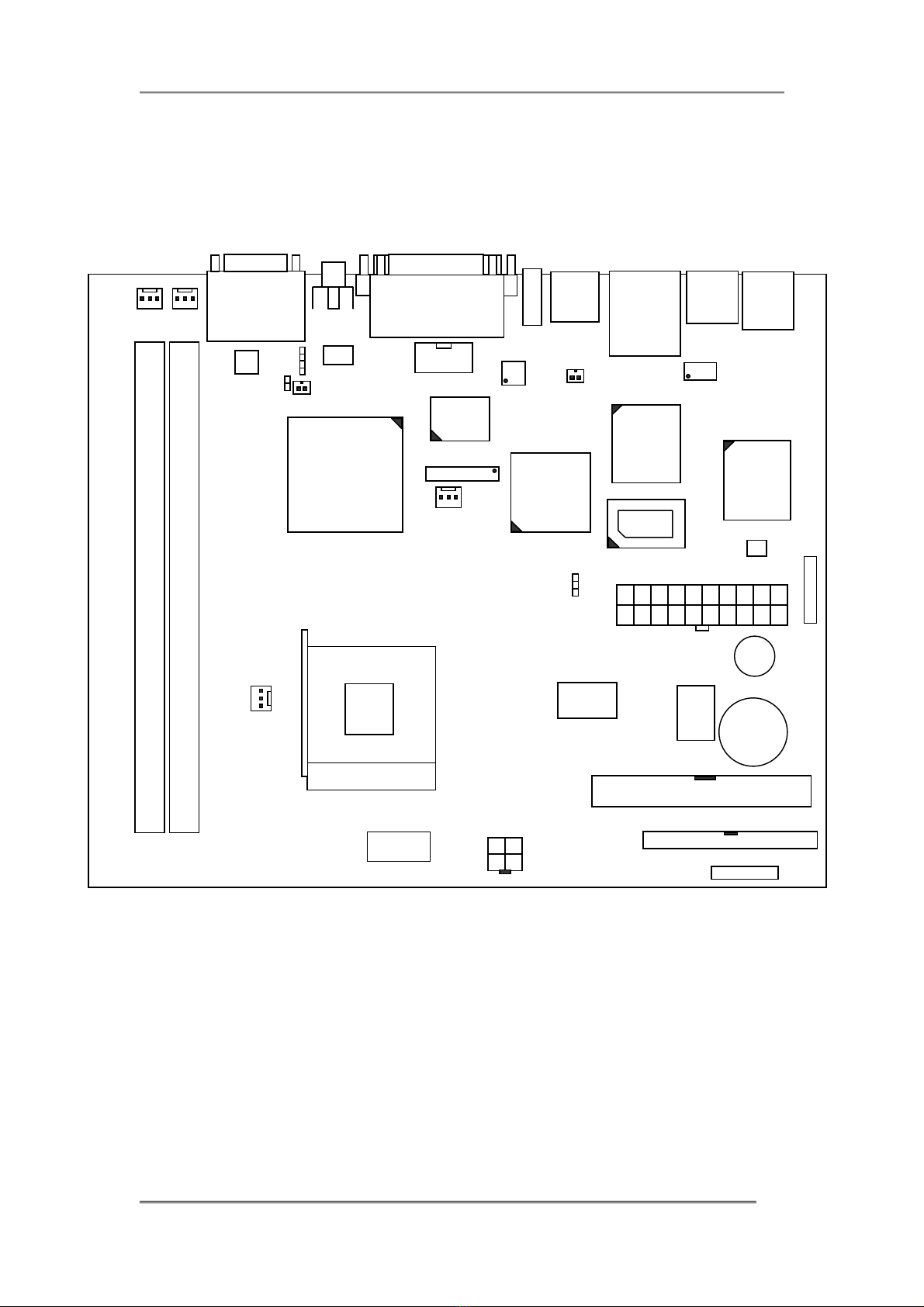
1.2 Layout……………………………………………………………………….. 2
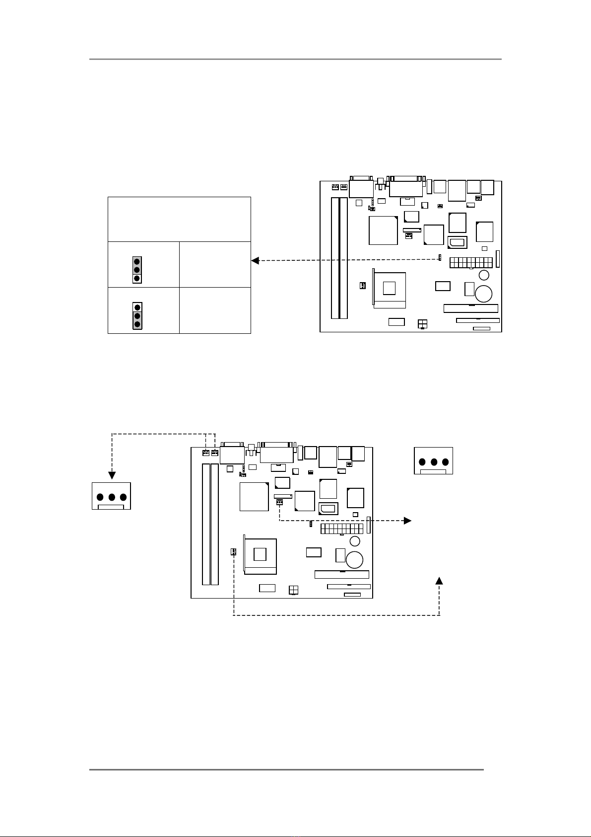
1.3 CPU Clock Setting…………….…………………………………………… 3
1.4 Jumpers & Connectors……………………………………………………. 4
Chapter 2 - Feature
2.1 Motherboard Components Placement………………………………….. 9
2.2 Block Diagram……………………………………………………………… 11
2.3 Specifications………………………………………………………………. 12
Chapter 3 - Hardware Setup
3.1 Before Installation………………………………………………………….. 14
3.2 Install the CPU……………………………………………………………… 14
3.3 Install Memory Modules…………………………………………………… 16
3.4 ATX Power Supply Connector……………………………………………. 17
3.5 Back Panel………………………………………………………………….. 18
Chapter 4 - BIOS Setup
4.1 Flash BIOS………………..………………………………………………… 19
4.2 Enter BIOS Setup program……………………………………………….. 19
4.3 Main Menu………………………………………………………………….. 21
4.4 Standard CMOS Features………………………………………………… 22
4.5 Advanced BIOS Features…………..….…………………………………. 25
4.6 Advanced Chipset Features……..……………………………………….. 29
4.7 Integrated Peripherals…………………………………………………….. 30
4.8 Power Management Setup……………………………………………….. 34
4.9 PnP/PCI Configurations…………………………………………………... 37
4.10 PC Health Status………………………………………………………… 38
4.11 Frequency/Voltage Control……………………………………………… 38
4.12 Load Optimized Defaults……………………………………………….. 39
4.13 Set Supervisor/User Password..………………………………………. 39

4.14 Save & Exit Setup……………………………………………………….. 39
4.15 Exit Without Saving……………………………………………………… 40
Chapter 5 – Driver Installation…………………………………………. 41
Chapter 6 – VGA Setting………………………………………………… 42

Chapter1 QuickInstallation
R860 1
Chapter 1 : Quick Installation
1.1 Item Checklist
[ √] R860 Motherboard
[ √] S-Video <> AV Video cable
[ √] 40-pin ATA 100/133 cable
[ √] Driver CD

Chapter1 QuickInstallation
R860 2
1.2 Layout
PS/2 KB
PS/2 Mouse
Modem (RJ11)
LAN Port
USB x 2 Ports
USB x 2 Ports
VGA COM1
LPT
MIC / LINE IN / LINE OUT
GAME Port
SiS M650
SiS 302LV
SiS 962
Winbond
W83697HF
REALTEK
RTL8139C
ICS 952001AF S1
Switch
IDE 2
ALC201A
IEEE 1394
TV-OUT
8552TS
COM 2
FW801A
BIOS
Battery
IDE 1
Buzzer
CN 1
PGA478B
JP2
FAN 4 FAN 3
FAN 1
CN 2
CD1
JP3
CN4
FAN 2
RT9237
ATX 1
JP1
CN 3
A
TMEL 93C46
CN5 GT TS6121A
1 3

Chapter1 QuickInstallation
R860 3
1.3 CPU Clock Setting
S1 : CPU Clock Setting
100MHz (400MHz CPU Clock Frequency)
133MHz (533MHz CPU Clock Frequency)
S1 : CPU Clock Setting
100MHz On On Off Off Off (1~5)
133MHz Off On On Off On (1~5)

Chapter1 QuickInstallation
R860 4
1.4 Jumper & Connectors :
JP1 : CMOS Clear
JP 1 : CMOS Clear
1-2 Close CLEAR CMOS
2-3 Close NORMAL
( default )
CPU & CHASSIS FAN Header : Connect RED line to 12V.
1 2 3
Pin Assignment
1 : GND
2 : 12V
3 : SENSE
1 2 3
Pin Assignment
1 : GND
2 : 12V
3 : None

Chapter1 QuickInstallation
R860 5
ATX Power Connector
ATX1
PIN NO Definition PIN NO Definition
1 +3.3V 11 +3.3V
2 +3.3V 12 -12V
3 GROUND 13 GROUND
4 +5V 14 Power Supply On
5 GROUND 15 GROUND
6 +5V 16 GROUND
7 GROUND 17 GROUND
8 Power Good 18 -5v
9 +5V Standby 19 +5v
10 +12V 20 +5v
CN2
1 GND 3 +12V
2 GND 4 +12V
1
11
10
20
1
2
4
3

Chapter1 QuickInstallation
R860 6
JP3 : SPDIF Header.
SPDIF Header
Pin 1 SPDIF
2 GND
CN4 : Speaker – Right Channel
CN5 : Speaker – Left Channel.
CN1 : Inverter Header.
CN1
Pin 1, 3, 5, 6, 8, 9 GND_LCD
Pin 2 BRIGHT
Pin 4 LIGHT_ON
Pin 7 None
Pin 10, 11, 12 +12V
1
2
Pin 1
+INTSPR / -INTSPR
Pin 1
+INTSPL / -INTSPL
CN5
CN4
Pin 1
12

Chapter1 QuickInstallation
R860 7
JP2 : LVDS Header
COM2 :
CD1 : CDROM Audio Connect Pin.
LVDS
1 LDC0- 16 LDC5+
2 LDC0+ 17 GND
3 LDC1- 18 LDC6-
4 LDC1+ 19 LDC6+
5 LDC2- 20 LL2C-
6 LDC2+ 21 LL2C+
7 GND 22 LDC7-
8 LL1C- 23 LDC7+
9 LL1C+ 24 GND
10 LDC3- 25 None
11 LDC3+ 26 VADE
12 LDC4- 27 None
13 LDC4+ 28 LCDVDD
14 GND 29 LCDVDD
15 LDC5- 30 LCDVDD
Pin 1
9
10 2
CD_R CD_LGND
NRIB / NRTSB / GND / NSOUTB / NDCDB
VCC / NCTSB / NDSRB / NDTRB / NSINB
Pin 1
Pin 29
Pin 30 Pin 2

Chapter1 QuickInstallation
R860 8
CN3 : Front Panel Control Header.
CN3
Pin 1, 2 Power On
Pin 3, 4 Reset
Pin 5, 6 LCD Up / Down
Pin 7, 8 Sound Up / Down
Pin 9, 10 Power LED
Pin 11, 12 HDD LED
CN6 : Mini-PCI Modem Card Connect Pin
(BACKSIDE)
CN6
Pin 1 TIP
Pin 2 RING
Pin 1
12

Chapter2 Feature
R860 9
2. Feature
2.1 R860 Motherboard (PCB Ver. A1) Components Placement
PS/2 Mouse
Keyboard
USB x 2
LAN 1
VGA
SiS 302LV
BIOS
ATX Power connector
DDR DIMM Sockets
SiS 962
TV OUT
AV
Line
OUT
MIC RJ11
RTL 8139C
LVDS Header : JP2
mPGA478
CPU Socket
LPT 1
COM 1
COM 2
USB x 2
Line
OUT
Joystick
FAN 3
FAN 4
Front Panel Control : CN3
Buzzer
Battery
S1 switch
IDE 2
IDE 1
ATX Power
Connector : CN2
IEEE 1394 x1
FAN 1 FAN 2
W83697HF
Inverter : CN1
R860

Chapter2 Feature
R860 10
R860 (PCB Ver : A1) Backside :
Mini PCI Socket : CN8
Mini-PCI Modem Card Connect Pin : CN6

Chapter2 Feature
R860 11
2.2 Block Diagram
SiS M650
Intel Pentium 4 / Celeron
Socket 478 CPU
DIMM x2 (100/133 MHz)
DDR200/266
Share for VGA memory
RTL 8139C
10/100 Mbps
LAN x1
Winbond
W83697HF
LPC ROM
- BIOS
- COM 1
- COM 2
- Parallel Port
- Joystick
- 2 Fan, Thermal Monitoring
AC97
(2Channel)
IDE x2 ports
ATA
133/100/66
IDE 1 : 2.5”HDD
IDE 2 : Slim Type
CD/DVD/COMBO-ROM
MIC IN
CD IN
Line OUT
PS2 KB / Mouse
LPC
PCI
Mini PCI
Device
SiS 302LV
CRT
TV (NTSC, PAL)
17” TFT-LCD
( LVDS )
Line IN
SiS 962
USB 2.0
x4 Ports
IEEE 1394A
x1 Port
PHY
FW801A
MuTIOL (533MB/s)
System Bus 400MHz

Chapter2 Feature
R860 12
2.3 Motherboard Specifications
Processor Support Intel Pentium4 – 400/533MHz system bus: 1.70GHz ~ 3.06GHz
Celeron – 400/533MHz system bus: 1.20GHz ~ 2.8GHz.
Chipset SiS M650 / 962.
Expansion Slot Mini-PCI Slot.
System memory 2 X DIMM (100/133MHz) DDR200/266/333, up to 1GB.
VGA Integrated in SiS M650 ( Shared memory 2 ~ 64MB )
( CRT : Support to 640x480 ~ 1280x720 resolutions )
LVDS / TV-OUT SiS 302LV chip
( LVDS : Support to 640x480 / 800x600 / 1024x768 / 1280x1024 resolutions )
( TV-OUT : Support NTSC/PAL 640x480 / 800x600 / 1024x768 resolutions )
Network Realtek 8139C 10/100Mbps Lan chip x 1.
Onboard I/O PS/2 Keyboard and Mouse Support.
RJ-11 Modem Port x1.
1 LAN ports for RJ-45 cable.
Supports 4 X USB (2.0) Ports.
IEEE 1394a x1 port.
2 Serial Ports (16550 Fast UART Compatible).
1 Parallel Port (ECP,EPP Port).
1 VGA Port.
1 TV-OUT port (Composite Video)
Sound (Line Out / Line In / MIC) (ALC201A codec, AC97, 2 channel) Port.
1 Joystick Port
.PCI Bus Master IDE Ports : support Ultra DMA 133/100/66..
Switching Voltage
Regulator
Support VRM ver. 8.4
BIOS BIOS with DMI, Green Fun., PnP, and Anti-virus.
Support USB/LS120/ZIP/CD-ROM Booting
2MB Firmware
Dimension 240mm x 180mm, Special Size.
Advance Features :
Power Management :
“Advance Configuration Power Interface” ( ACPI ) Standard ready for PC’99.
Power Off by Windows 98/ME/XP Shut Down & Soft Power Switch (ATX Power Require)
Monitoring Function :
Vital voltages on the power supply.

Chapter2 Feature
R860 13
CPU temperature.
CMOS battery voltage.
Fan speed, and Hard drive memory resources.
CD-ROM :
USB 2.0 Driver.
Video Driver.
Audio Driver.
Lan Driver
User’s Manual

Chapter3 HardwareSetup
R860 14
3. Hardware Setup
3.1 Before Installation
For installation, you may need tool (screwdriver).
Users must follow these guidelines to ensure the motherboard is protected
during installation.
1. Make sure your computer is powered-off whenever work in with inside
components.
2. The motherboard, like all other electronic equipment, is sensitive to static.
Please take the proper precautions when handling it. If possible, ground
yourself by touching a metal table or desk. Keep the board in its conductive
wrapping until it is configured and ready to be installed in your system.
3. Keep all magnets away from both your hard and floppy disk drives,
especially magnetic screwdrivers. Keep both floppy and hard disks apart if
disassembled.
4. Keep water and liquids away from your computer and its components
3.2 Install the CPU
The CPU should have a fan attached to it to prevent overheating. If this is not
the case, then purchase a fan before you turn on your system.
Be sure that there is sufficient air circulation across the CPUs heat sink by
regularly checking that your CPU fan is working. Without sufficient circulation,
the processor could overheat and damage both the CPU and the motherboard.
You may install an auxiliary fan, if necessary.

Chapter3 HardwareSetup
R860 15
Step 1 : Locate the ZIF socket and open it by first pulling the lever of socket upward.
Step 2 : Insert the CPU into the socket. Please keep the lever angle when inserting CPU.
When inserting the CPU please note the correct orientation as shown.
The notched corner should point toward the end of the lever.
Step 3 : Push the lever down to close the socket.
Table of contents