Classeq CST Quick start guide

ENGINEERS MANUAL CST MACHINES AND DRYER UNIT
Drawn up: 05/10/2018
Document number : 30008893
Page 1 of 48
Revision: C
CST Machines

ENGINEERS MANUAL CST MACHINES AND DRYER UNIT
Drawn up: 05/10/2018
Document number : 30008893
Page 2 of 48
Revision: C

ENGINEERS MANUAL CST MACHINES AND DRYER UNIT
Drawn up: 05/10/2018
Document number : 30008893
Page 3 of 48
Revision: C
Contents
1. Introduction................................................................................................................................. 4
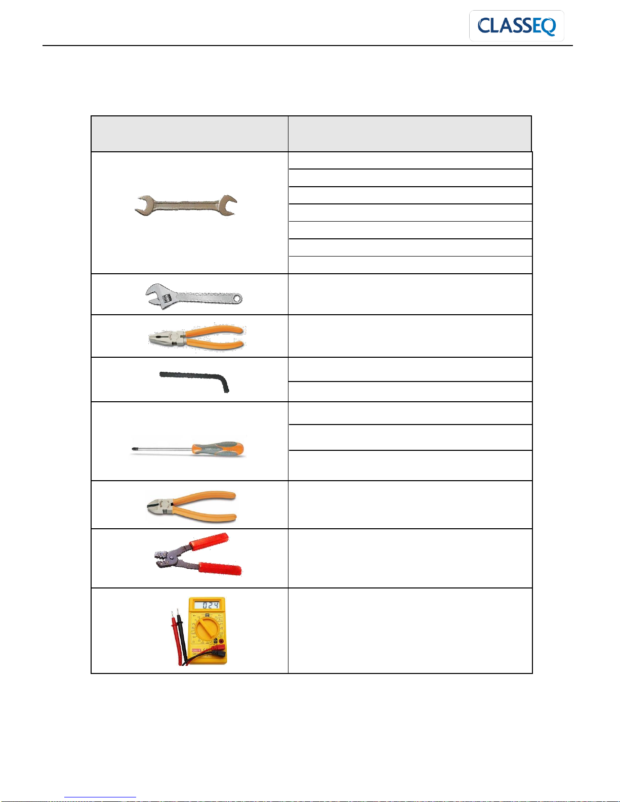
2. Recommended Tool Kit.............................................................................................................. 5
3. Machine Specifications............................................................................................................... 6
4. Installation Instructions............................................................................................................... 7
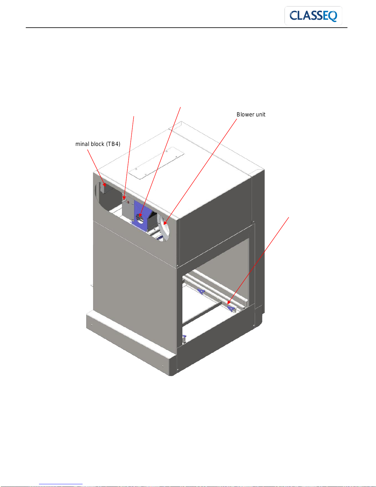
5. Know your unit............................................................................................................................ 7
6. Warning and safety information.................................................................................................. 9
7. Site requirements...................................................................................................................... 10
8. Commissioning Instructions...................................................................................................... 14
9. Water Systems ......................................................................................................................... 18
10. Electrical Component Data....................................................................................................... 19
11. Changing orientation................................................................................................................. 20
12. Speed setting............................................................................................................................ 24
13. Setting basket arm.................................................................................................................... 26
14. Machine wiring and layout........................................................................................................ 27
15. Dryer unit wiring and layout...................................................................................................... 41
16. Trouble shooting....................................................................................................................... 46

ENGINEERS MANUAL CST MACHINES AND DRYER UNIT
Drawn up: 05/10/2018
Document number : 30008893
Page 4 of 48
Revision: C
1.Introduction
Introduction:
Prior to reading this manual, it is essential that you are familiar with the contents and subject matter
covered within the ‘Installation & Operators Manual’ or ‘Installation instruction’.
Installation:
Installation should only be carried out by a Classeq approved technician, in accordance with current
regulations and within our instructions.
Repairs and spare parts:
The appliance must only be repaired by a Classeq approved technician, using genuine Classeq
spare parts, failure to do so could invalidate any warranty and relieve the manufacture of all liability.
Modification:
Classeq reserves the right to modify either the appliance or the contents of these instructions without
notice.
CAREFULLY READ THESE INSTRUCTIONS, BEFORE INSTALLING AND OPERATING OR REPAIRING
THIS APPLIANCE.
INCORRECT INSTALLATION, ADAPTATIONS OR ALTERATIONS COULD RESULT IN INJURY OR
DAMAGE TO PROPERTY.
MALICIOUS DAMAGE, DAMAGE DUE TO NEGLIGENCE, OR FAILURE TO COMPLY WITH THESE
INSTRUCTIONS AND LOCAL LEGISALTION, OR UNAUTHORISED TAMPERING WILL INVALIDATE
ANY WARRANTY AND RELIEVE THE MANUFACTURER OF ALL LIABILITY
DAMAGE CAUSED DUE TO THE LACK OF, OR INCORRECT USE OF A WATER SOFTNER, OR
LIMESCALE DAMAGE WILL NOT BE COVERED BY THE MANUFACTURES WARRANTY

ENGINEERS MANUAL CST MACHINES AND DRYER UNIT
Drawn up: 05/10/2018
Document number : 30008893
Page 5 of 48
Revision: C
2.Recommended Tool Kit
Recommended hand tools
Specification
5.5mm - Spanner / nut runner / socket
7.0mm - Spanner / nut runner / socket
8.0mm - Spanner / nut runner / socket
10.0mm - Spanner / nut runner / socket
13.0mm –Spanner / nut runner / socket
24.0mm - Spanner / nut runner / socket
32.0mm - Spanner / nut runner / socket
10mm to 18mm - Adjustable spanner
Pliers
2.5mm Hex key
3mm Hex key
No. 2 - Pozi screw driver
Electric screw driver (small)
Flat bladed screw driver (large)
Wire cutters
Wire crimpers
Multi meter capable of measuring:
Volts (10V ~ 240V AC)
Amps (0 ~ 50 Amps)
Ohms (0 ~ 30MΩ)
Continuity

ENGINEERS MANUAL CST MACHINES AND DRYER UNIT
Drawn up: 05/10/2018
Document number : 30008893
Page 6 of 48
Revision: C
3.Machine Specifications
Door opening angle
180°
Maximum clear entry height
492mm
Operating noise level*
<70dB
Net weight
180kg
Gross weight
268kg
Built in air gap (WRAS Approved)
Yes
Rinse booster pump
Yes
Built in Detergent dispenser
No
Built in Rinse aid dispenser
No
Auto timer
Yes
Racks per hour
100 - 130
Water connection
G¾” (¾” BSP)
Water inlet height from floor level
170 - 240mm
Required water pressure
2 –4 bar
Maximum drain height from floor
270 –320mm
Drain size
Ø40
Amps required –3 phase
Water fed @ 40°C
32A
Water fed @ 10°C
45A
Total connected load
Water fed @ 40°C
13.74kW
Water fed @ 10°C
25.74kW
Operating voltage
380-415V
Wash tank element
2x6kW
Rinse boiler element
4x6kW
Rinse boiler capacity
7Lts
Wash pump power
1.1kW
Wash tank capacity
80Lts
Wash water operating temperature
55°C –60°C
Rinse pump power
0.25kW
Rinse water operating temperature
>82°C
Rinse water consumption
4.7Lts/min
Drive motor
0.37kW
Dryer air temperature
60°C
Blower power
0.5kW
Dryer tunnel amps
+12A
Dryer tunnel connected load
+4.5kW
Water consuption
282Ltrs/hour

ENGINEERS MANUAL CST MACHINES AND DRYER UNIT
Drawn up: 05/10/2018
Document number : 30008893
Page 7 of 48
Revision: C
4.Installation Instructions
The site:
Ensure that there is sufficient space for the installation, servicing and easy access to
all mains isolator switches / valves (i.e. electricity and water).
Ensure that the surface the appliance is going to be installed onto is adequately stable
and capable of supporting the appliance during normal operation (see site
requirements).
Once installed ensure the appliance is stable, with its weight being distributed equally
and does not tilt more than 3° in any direction.
Adjuster feet:
After removing the machine from the transport pallet ensure all the feet are adjusted to suit the
surface where the appliance is being installed.
For further instructions see installation and operation manual.
5.Know your unit
Machine layout
* Take note of safety information regarding these components (►6)
Wash pump
Rinse boiler
Rinse pump
Control panel (dryer
controls on rear)
Wash arms and
fitting tubes
Rinse arms
Curtain
s
Gear box &
Drive motor*
Cassette
assembly
*
Filter
Fascia and controls
Serial number /
Electrical rating plate
Wash tunnel*
Thermostats
Curtain
bracket
Dryer terminal
block (TB3)

ENGINEERS MANUAL CST MACHINES AND DRYER UNIT
Drawn up: 05/10/2018
Document number : 30008893
Page 8 of 48
Revision: C
Dryer unit layout
Dryer cassette
Blower unit
Dryer element*
Dryer thermostat
Blower terminal block (TB4)

ENGINEERS MANUAL CST MACHINES AND DRYER UNIT
Drawn up: 05/10/2018
Document number : 30008893
Page 9 of 48
Revision: C
6.Warning and safety information
The machine should only be operated at or within the voltage specified on the rating plate (►5). The
installer and user are responsible for ensuring the installation and operation of this machine are in
accordance with local and national regulations.
The machine is not fitted with a heat interlock but should be allowed to fully heat to the correct
temperatures before use.
Only use commercial grade detergents and rinse-aids within your machine.
DO NOT use electrical extension lead(s) to supply power to your machine.
Damage to the machine caused by lime scale, or poor water quality will NOT be covered by the
Manufacturer’s Warranty.
Children should be supervised to ensure that they do not play with, or operate the machine.
When disconnecting your machine from the mains electrical supply:
Machines hard wired (i.e. no plug), this must be disconnected in accordance with local and national
regulations; Classeq recommends this is performed by a qualified electrician.
Always remove excess food from the dishes before loading.
Caution
DO NOT use the machine
as a waste disposal unit.
Do not insert any items or parts of your body between moving components, as this could cause injury.
Beware of touching or placing items onto the wash tunnel of the machine, as this can get hot during use.
The drive motor and gearbox assembly weighs over 15kg. When removing these items care must be
taken to ensure that the weight is supported correctly.
The dryer unit weighs more than 50kg and should be handled with care. When installing the unit a lifting
trolley should be used.

ENGINEERS MANUAL CST MACHINES AND DRYER UNIT
Drawn up: 05/10/2018
Document number : 30008893
Page 10 of 48
Revision: C
7.Site requirements
Machine dimensions:
Dishwashers
CST
With dyer
Machine
(mm)
A = width
(mm)
1300
2000
B = depth
Closed (mm)
810
Open (mm)
1490
C = height
(mm)
1380-1440
1730-1790
Basket size (mm) (square basket)
500
Load capacity (dishes)
18
Load capacity (pint glass)
30
Basket rate (Baskets/hour)
100 / 130
Rinse running water temperature
82°C
Rinse standby water temperature
60°C
Wash water temperature
55°C
B
C
A
B

ENGINEERS MANUAL CST MACHINES AND DRYER UNIT
Drawn up: 05/10/2018
Document number : 30008893
Page 11 of 48
Revision: C
Electric Supply:
Electrical connection:
Electrical connections MUST be carried out by an authorized technician and in accordance with local
and national regulations.
As a minimum Classeq recommends the following standards are maintained:
All appliances are connected via a residual current device (R.C.D.) or earth leakage protection device.
EN60204:
Supply isolator switch has all pole separation of more than 3mm.
EN60335:
Connect to an equi-potential conductor, connection stud located at bottom of the appliance to the rear;
this is in addition to the earthed electrical supply.
Prior to connecting the appliance, ensure voltage and supply fuse comply with rating plate.
Electrical rating: Note: Electrical supply can be
either side of the appliance. The
appliance not supplied with the
electrical plugs.
If the supply cable is damaged ,
it must be replaced by a cable or
cord assembly supplied by
Classeq or its service agents or
to the following minimum
specification.
Cable type
Temperature
rating
Length of cable
Confirm to /
standard
H07RN-F
5G10
80°C minimum
5m
IEC 60335-2-58
&
IEC 60227 types
56 & 57
Electrics
CST
Dryer unit
Volts
380 –415V (3
Phase)
380 –415V (3
Phase)
Amps
Hot fill
32A per phase
+12A per phase
Cold Fill
45A per phase
Max total load
Hot fill
13.74kW
+4.5kW
Cold Fill
25.74kW

ENGINEERS MANUAL CST MACHINES AND DRYER UNIT
Drawn up: 05/10/2018
Document number : 30008893
Page 12 of 48
Revision: C
Water Inlet and Waste out let:
Water connection:
The appliance comes with a water supply hose requiring
a G¾” (¾” BSP) male threaded connection at the mains
water supply, upon installation and commissioning all
water joints must be checked for leaks.
Old existing, defective or damaged water supply hoses
are NOT to be used when installing the appliance.
Commercial appliance wash results will be affected by
external conditions such as incoming water
temperature, pressure, harness and choice of
chemicals.
For the longevity of any water related devices and to
ensure you get consistently good results it is essential your machine is either fed from a soft water
supply , or your Classeq appliance is connected to an appropriate water softener.
Note: Water supply can be either side of the machine.
IMPORTANT:
All supplier warranties are void if lime scale is present within an appliance
If the above requirements are not adhered to, the performance of the appliance will be impaired
CST 100 / 130
Temperature range
5-55°C
Pressure
0~2 bar
Booster pump required
2~4 bar
No modification
4~6 bar
Flow restrictor required
6 bar +
Pressure reducing valve
required
Flow rate
4.7 Lts / min
Water connection
G ¾” (¾” BSP)
Inlet valve
Waste outlet / Drain hose

ENGINEERS MANUAL CST MACHINES AND DRYER UNIT
Drawn up: 05/10/2018
Document number : 30008893
Page 13 of 48
Revision: C
Waste outlet:
The CST is a gravity drain machine, upon installation the
waste must be configured as stated in this manual.
All installations should be fitted with a running ‘P’ trap to
ensure hygiene.
Ø40mm (1 ½”) standpipe required, must be lower than
the baseline of the wash tank.
Drain hose must be a close / tight fit into the drain pipe
to reduce odours from the drain system.
To ensure correct drainage, the height the sites drain is from the floor / surface the machine sits
upon MUST be within the following
Waste hose must flow down from the waste outlet to the drain.
Joint between standpipe and waste hose must be water tight.
If you have any doubts about the drainage system on the machine, please contact either Classeq or
your dealer/agent.
Terminal block layout
Terminal block (TB1) configuration (Mains supply):
Drainage dimensions
(mm)
CST
Drain stand pipe diameter
Ø40
Maximum drain pipe
height (Gravity drain)
(Depending on height
adjustment)
270 - 330mm
4mm² wires for heating
10mm² incoming mains cable
0.75mm² cable to pumps
0.5mm² neutral cable to Filter
4A
1.5mm² cable to control
harness and pumps
1.5mm² earth cable
0.75mm² cable to dryer
unit (if fitted)

ENGINEERS MANUAL CST MACHINES AND DRYER UNIT
Drawn up: 05/10/2018
Document number : 30008893
Page 14 of 48
Revision: C
8.Commissioning Instructions
Rinse aid & Detergent:
The CST is not fitted with internal chemical dosing pumps, these will need to be fitted during the
installation.
A terminal block is provided on right hand side of the wash tank for connecting the electrics of the
chemical pumps.
Note: Isolate the machine prior to the access and connection of the chemical pump terminal block.
WARNING: Only rinse aids and detergents developed for commercial glass and
dishwashers are to be used, rinse aids must be suitable for water temperatures down to
40°C.
Terminal block configuration (Chemical pumps):
Yellow/green
Blue
orange
Purple
Brown
Earth
Neutral
Running
WT full
Live

ENGINEERS MANUAL CST MACHINES AND DRYER UNIT
Drawn up: 05/10/2018
Document number : 30008893
Page 15 of 48
Revision: C
Machine temperature settings:
The water temperatures on ’Classeq’ range of machines are adjustable, but have been pre-set to:
Thermostat positions
Rinse thermostat –
standby (ST1)
Rinse thermostat –
Running (ST2)
Wash thermostat
(ST3)
60ºC
82ºC
55ºC –60°C
Dryer temperature setting
The air temperature on the ’Classeq’ dryer range is adjustable, but have been pre-set to:
Dryer air temperature
(ST4)
60ºC
The manual reset safety thermal trips on the machine are set to the following values and cannot be
adjusted:
Wash tank –85°C
Rinse boiler –95°C
Air blower –85°C
Table end limit switch
It is very important that the table end limit switch be installed at the end of the exit table and the arm
adjusted so that it is activated by the basket before it reaches the end of the table. The cable should
be routed through the small cable gland at the rear of the machine and plugged into the harness at the
connector near the small terminal block. The switch should be wired on the normally closed circuit.

ENGINEERS MANUAL CST MACHINES AND DRYER UNIT
Drawn up: 05/10/2018
Document number : 30008893
Page 16 of 48
Revision: C
This switch will stop the machine when activated allowing the operator time to remove the clean
baskets before more baskets are pushed through the machine.
Min. 50mm
Adjustable 20-70mm
Cable gland
Terminal
block

ENGINEERS MANUAL CST MACHINES AND DRYER UNIT
Drawn up: 05/10/2018
Document number : 30008893
Page 17 of 48
Revision: C
Electrical supply setup
If the machine is fitted to a hot water supply (maximum temperature of 55°C) then the electrical supply
to the machine can be changed (►7). This is done by turning off CB2, this turns off one of the banks
of elements used in the rinse boiler and reduces the current required.
Cold fill (45A per phase)
Hot fill (32A per phase)
Installing the splash guard (only if not dryer fitted)
Once the machine has been installed and all tabling has been aligned the splash guards should be
fitted to the exit of the machine.
Remove the 3x M5 screws on either side of the exit and use these to fasten the splash guard in place.
Align the splash guard to the front of the machine and the side of the exit as best as possible. Once
fitted the splash guards should be sealed against the tabling.
CB2 OFF
CB2 ON

ENGINEERS MANUAL CST MACHINES AND DRYER UNIT
Drawn up: 05/10/2018
Document number : 30008893
Page 18 of 48
Revision: C
9.Water Systems
Rinse system (Also used for filling the wash tank):
Wash system:

ENGINEERS MANUAL CST MACHINES AND DRYER UNIT
Drawn up: 05/10/2018
Document number : 30008893
Page 19 of 48
Revision: C
10. Electrical Component Data
Component
Voltage
(V)
Frequancy
(Hz)
Current
(A)
Power
(W)
Resistance
(Ω)
Inlet solenoid
valve
220 ~ 240
50 ~ 60
-
-
-
Rinse elements
4 x (3x2kW)
230
50 ~ 60
8.7 / leg
2000 / leg
26.42 / leg
Wash elements
2 x (3x2kW)
230
50 ~ 60
8.7 / leg
2000 / leg
26.42 / leg
Rinse pump
220 ~ 240
50
1.2 (Running)
250
Wash pump
380 ~ 415
50
2.8
1100
Drive motor
380 ~ 415
50
1.23
370
Contactors
220 ~ 240
50
Timer
220 ~ 240
50
Relays - (Finder)
220 ~ 240
50
Indicator lamps
White (LED)
220 ~ 240
50 ~ 60
Amber
220 ~ 240
50 ~ 60
Blue
220 ~ 240
50 ~ 60
Red
220 ~ 240
50 ~ 60
Air pressure
switches
220 ~ 240
50 ~ 60
Temperature
display
220 ~ 240
50 ~ 60
Blower unit
380 ~ 415
50
1.05
500
Air heater
element
3x 2kW
230
50 ~ 60
8.7
2000
26.42

ENGINEERS MANUAL CST MACHINES AND DRYER UNIT
Drawn up: 05/10/2018
Document number : 30008893
Page 20 of 48
Revision: C
11. Changing orientation
CST is designed to allow adaption to a change in direction of travel during the commissioning of the
machine.
Ensure the machine is fully drained prior to commencing any changes.
Remove all the curtains and the cassette assembly from the machine.
Danger
For safety reason turn
off all electrical
supplies to your
machine before
following these steps.
Remove rear top and rear bottom panels in order to get access to wash and rinse hoses.
When changing the direction of the CST care must be taken not to misplace or damage the sealing O-
rings.
11.1 Changing wash and rinse arms system.
Remove the wash arms and cassette from the machine.
Remove wash arm brackets and fixing tubes. Take note shorter fixing tubes used at bottom and
longer fixing tube used at top.
Remove rinse arm hose from rinse bush.
Remove rinse arms and associated brackets.
Loosen and remove the top wash manifold.
Remove the blanking covers from the remaining holes
Loosen the jubilee clips for the bottom wash manifold.
Rotate the bottom wash manifold 180° to the new position and fasten using long fixing tubes.
C= CST Middle wash hose
C
Table of contents
Other Classeq Dishwasher manuals

Classeq
Classeq H750 Guide

Classeq
Classeq P500AS User manual

Classeq
Classeq DUO 750 Installation instructions

Classeq
Classeq ECO 3 Installation instructions

Classeq
Classeq D12000 Installation instructions

Classeq
Classeq P500A User manual

Classeq
Classeq ECO 2 Administrator Guide

Classeq
Classeq P500 User manual

Classeq
Classeq C200G Administrator Guide

Classeq
Classeq D 400 Instruction manual

Classeq
Classeq DUO 750 Administrator Guide

Classeq
Classeq P500 Instruction manual

Classeq
Classeq G 350 Quick start guide

Classeq
Classeq G 350 User manual

Classeq
Classeq D 400 User manual

Classeq
Classeq CST 100 Installation instructions

Classeq
Classeq HYDRO 850 User manual

Classeq
Classeq D 400 Instruction manual