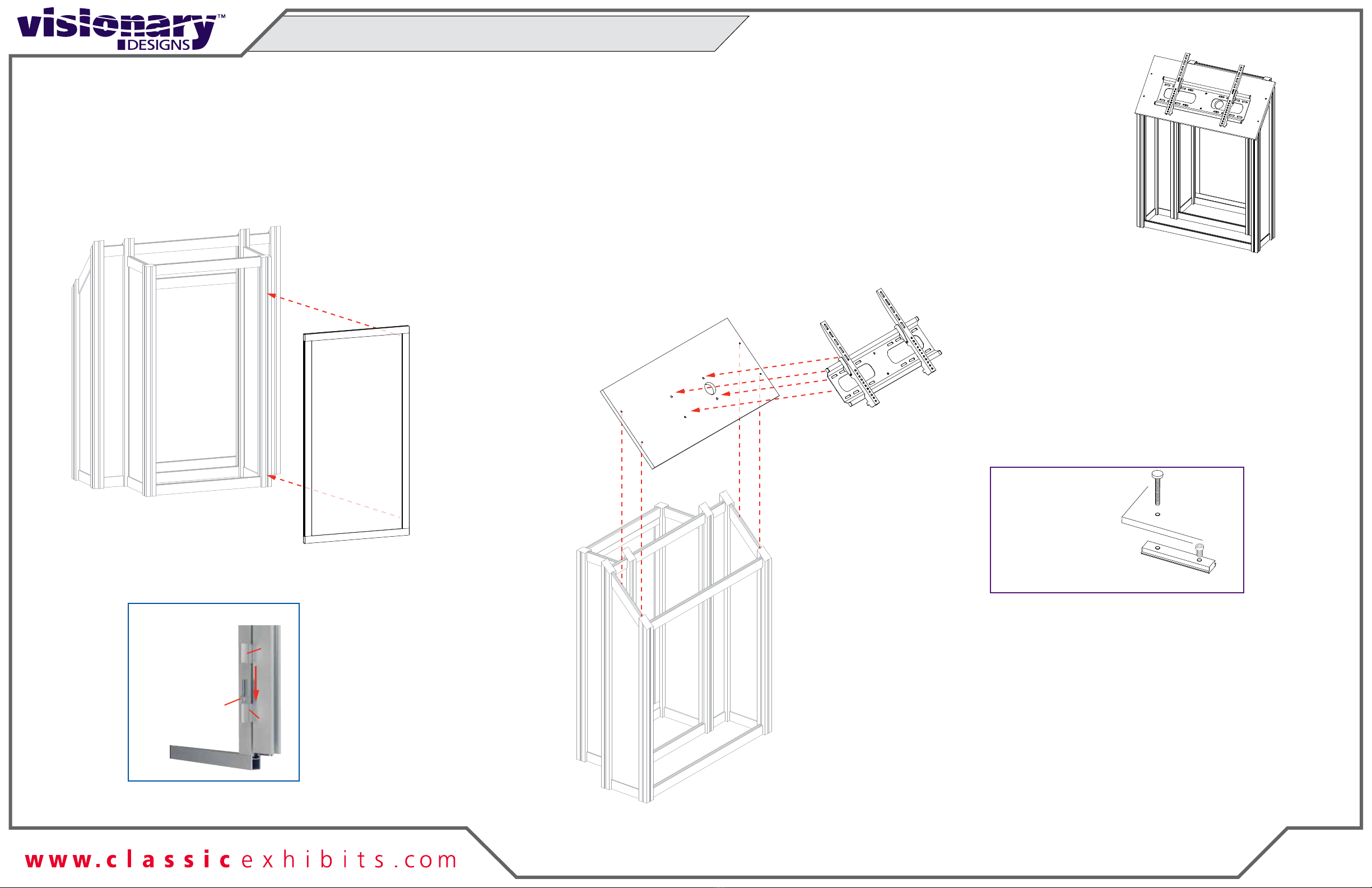
Classic Exhibits visionary DESIGNS MOD-1710 Manual

© 2023
Order #XXXXX
Locked layer contains
placeholder marks.
FRONT VIEW
TOP VIEW
= 1 sq foot
MOD-1710 Interactive Kiosk
If you would like to tell us about your experience with your setup instructions please email us at [email protected]
SETUP INSTRUCTIONS

© 2023
Order #XXXXX
DO NOT USE POWER TOOLS
ALL CONNECTIONS MUST
BE TIGHTLY SECURED
Part Identification - Numbering
Spline Connection Base Plate & Extrusion Connection
General Setup Instructions
- Read entire setup instruction manual prior to
unpacking parts and pieces.
- The setup instructions are created specifically
for this configuration.
- Setup instructions are laid out sequentially in
steps, including exploded views with detailed
explanation for assembly.
WARNING
Cleaning & Packing
- For Cleaning Metal, Plex, & Laminate Parts:
Use a MILD NON-ABRASIVE cleanser and
soft cloth/paper towel to clean all surfaces.
- Keep exhibit components away from heat
and prolonged sun exposure.
Heat and UV exposure will warp and
fade components.
- Retain all provided Packing Materials.
All provided packing materials are for
ease of repacking & component protection.
Disassembly
- For loss prevention, tighten all set screws
and locks during disassembly.
7A
Hex Tool - Essential for Assembly
Extrusion & Lock Connection Engaged Lock
LADDERS OR LIFTS
MAY BE REQUIRED
General Information

© 2023
Order #XXXXX
CEI-110 Profile
Straight Bracket Assembly
1) Slide TWO-PIECE TS RV 4 straight bracket into
Interior Center Slot of extrusion, so that two of the
set screws are inside groove. Tighten two set screws
to secure.
3) Slide connecting extrusion over exposed ends of
bracket & connector. Tighten all remaining set screws
to secure extrusions.
2) Slide one V4 Connector into outer interior groove
of extrusion, so that one set screw is inside groove.
Tighten set screw.
TS RV 4
Bracket
V4
Insert two-piece
bracket into the
interior center slot
of extrusion.
Slide V4 Connector
into front interior
groove.
Secure inserted half of
bracket & connector
using set screws.
Slide connecting
extrusion over
exposed ends
of bracket &
connector.
Completed
Assembly
Secure extrusion,
using remaining
set screws.
Set
Screws
Straight Connection
Corner Connection
TS RV 2
Upper
Horizontal
Lower
Horizontal
Upper
Horizontal
Lower
Horizontal
TS RV 2
8 Brackets Total:
(4) - TS RV 2
(4) - A1 L-Brackets
A1
A1
Slide verticals over
brackets of lower
horizontal, then slide
upper horizontal &
brackets into grooves
& center slots
of verticals.
Completed
Assembly
Insert L-Brackets into the
Interior Center Slot & outer
interior grooves of extrusion.
Disassembly
1) Loosen set screws on brackets and slide
extrusions off of brackets.
1) Slide TWO-PIECE TS RV 2 L-bracket into
Interior Center Slot of extrusion so that two
set screws are inside groove.
Tighten two set screws to secure.
2) Slide one A1 L-Bracket into outer interior
grooves of upper and lower horizontals.
Tighten set screws to secure.
4) Slide exposed ends of installed brackets of
upper horizontal into open ends of verticals.
Tighten set screws to secure.
3) Slide vertical extrusion over exposed ends
of brackets in lower horizontal.
Tighten set screws to secure.
Corner Bracket Assembly
CEI-110 Frame Assembly
CEI110 Frame Assembly

© 2023
Order #XXXXX
Graphic Removal
To remove the graphic
the frame, locate the fabric
pull tab.Gently pull up on the
tab to remove the fabric.
Step 1
Insert corner A. Turn edge of
graphic so silicon welt is
perpendicular to face of
graphic. Insert narrow side
of welt with fabric to outside
into the channel. Repeat for
other side of this corner.
Step 2
Repeat Step 1 for opposite
corner C, then insert corner
B, followed by corner D, to
complete the installation of
the corners.
Step 3
Once all corners are inserted,
press one silicon edge into
channel from corners and
work toward the center.
Make sure welt is fully inserted
into channel. Continue until
all sides are done. Smooth
out edges of graphic.
It is important to first insert
graphic into each alternate
corner then to the sides of
the frame. If this is not done,
graphic will not fit into the
frame correctly.
Corner A
Corner D
Corner B
Corner C
from
SEG Installation

© 2023
Step 1 of 4
Order #XXXXX
Locked layer contains
placeholder marks.
FRONT VIEW
Steps:
Refer to the CEI110 Frame Assembly general information page.
1) Assemble verticals [1,2] between horizontals [3,4], inserting Sintra blocker.
2) Connect power cords to Supernova lights as shown.
When assembled
Item
1
2
3
4
Qty.
1
1
1
1
Description
33”h CEI110 Vertical Extrusion
35.5”w CEI110 Horizontal Extrusion
1
2
3
4
Blocker
Transformer
+
-
Power
Female
Transformer
96W / 4 Amp / 24V
++
--
Lights Male
Light to Light Attachment
Maximum of 7 lights per chain / 7 lights per Transformer
Light to Transformer Attachment
Counter Assembly

© 2023
Step 2 of 4
Order #XXXXX
Locked layer contains
placeholder marks.
Steps:
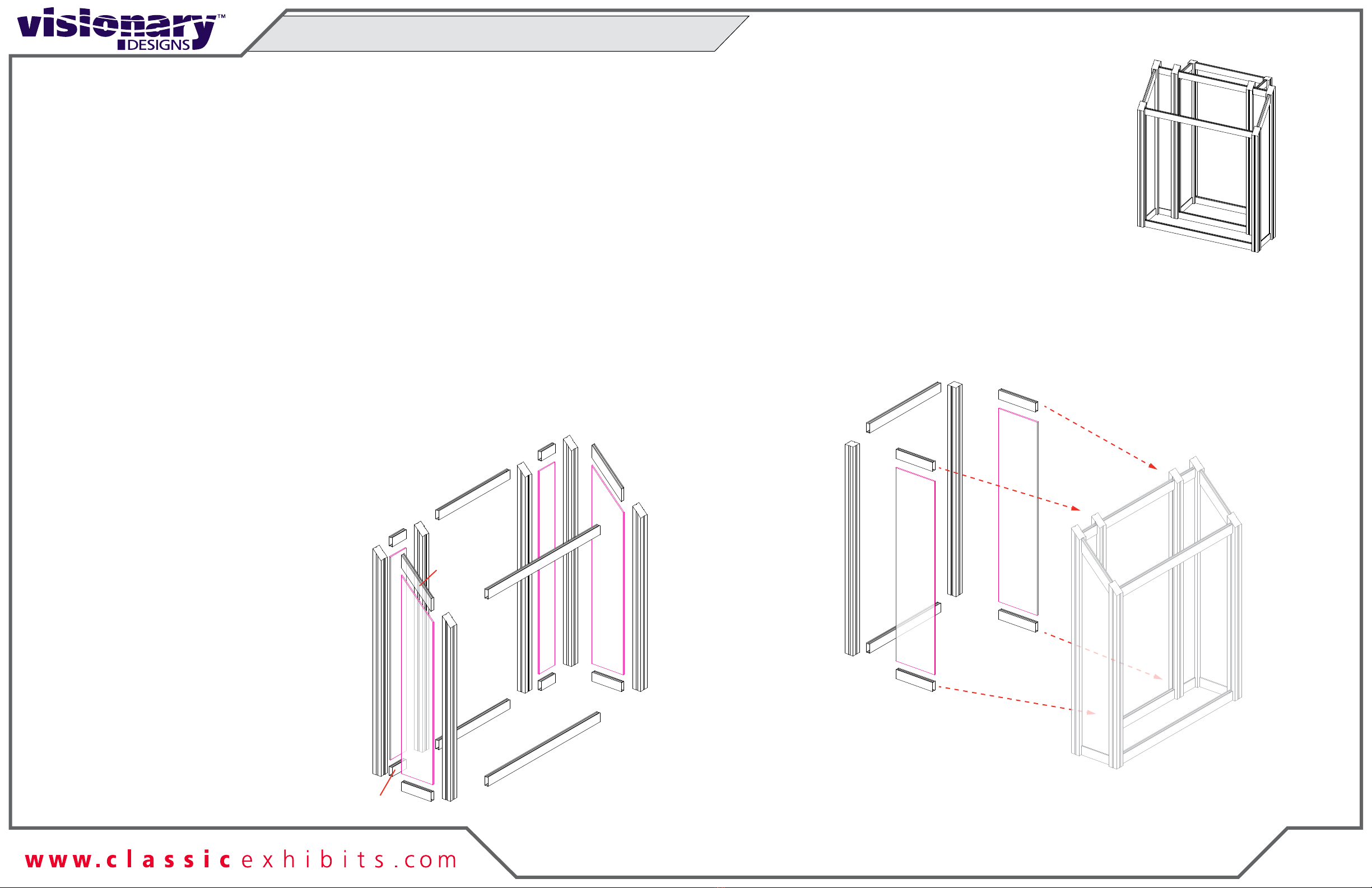
1) Assemble lower horizontals [11,13,15,17,18,19] between verticals [5,6,7,8,9,10].
2) Slide Infills between verticals [5,10], [6,7], [7,8], [9,10].
3) Connect upper horizontals [12,14,16,20,21,22] between verticals [5,6,7,8,9,10],
securing infills.
4) Assemble horizontals [25,26] between verticals [23,24].
5) Connect horizontals [27,28], [29,30] between verticals [23,24] & verticals [8,9],
inserting Infills.
Item
5
6
7
8
9
10
11
12
13
14
15
16
17
18
19
20
21
22
23
24
25
26
27
28
29
30
Qty.
1
1
1
1
1
1
1
1
1
1
1
1
1
1
1
1
1
1
1
1
1
1
1
1
1
1
Description
36.098”h S44 Vertical Extrusion
44.5”h S44 Vertical Extrusion
31.846”w Z41 Horizontal Extrusion
6.591”w Z41 Horizontal Extrusion
11.112”w Z41 angled Extrusion
6.591”w Z41 Horizontal Extrusion
11.112”w Z41 angled Extrusion
4”w Z41 Horizontal Extrusion
20.224”w Z41 Horizontal Extrusion
4”w Z41 Horizontal Extrusion
20.224”w Z41 Horizontal Extrusion
4”w Z41 Horizontal Extrusion
41.325”h S44 Vertical Extrusion
20.224”w Z41 Horizontal Extrusion
8.189”w Z41 Horizontal Extrusion
5
6
11
12
13
15
16
17
20
21
22
18
19
14
7
8
9
10
Infill
Infill
Infill
Infill
8
9
Infill
Infill
23
24
25
26
27
28
30
29
When assembled
Counter Assembly (cont’d)

© 2023
Step 3 of 4
Order #XXXXX
Locked layer contains
placeholder marks.
Monitor
Mount
Monitor Mount
Panel
BACK VIEW
Steps:
1) Attach Door between verticals [23,24]. See Door Attachment detail.
2) Connect Monitor Mount to Monitor Mount Panel, using bolts & wing nuts.
3) Attach Monitor Mount Panel to horizontals [14,16], using bolts & V4 connectors.
See V4 Connectior detail.
Door
Hinge
Hinge
Slide pin into
hinge attached
to vertical.
Slide door
hinge over pin.
Door Attachment
*
Pin
When assembled
*
*
Door
Item
--
--
--
Qty.
1
1
1
Description
Cabinet Door
35.5”w x 12.169 Monitor Mount Panel
Monitor Mount
14
16
V4 Connector
Slide V4 connector into
groove of extrusion &
secure with set screw.
Attach bolt to V4 connector.
*
set
screw
V4 Connector
**
**
23 24
Counter Assembly (cont’d)

© 2023
Step 4 of 4
Order #XXXXX
Locked layer contains
placeholder marks.
*BACK VIEW
Steps:
1) Connect Counter Top to top of horizontals [26,28,30]. See Counter Top Attachment detail.
2) Connect lightbox frame assembly [1/2/3/4] to front of verticals [5,6] using
bolts & V4 connectors. See Lightbox Attachment detail.
3) Apply SEG Graphic to front of lightbox assembly. Refer to the SEG Installation
general information page.
When assembled
Item
--
Qty.
1
Description
39”w x 12”d Counter Top
BACK VIEW
V4
Connector
set
screw
bolt
Extrusion
Lightbox
Lightbox Connection
*
Slide V4 connector into groove of vertical
extrusion as shown; secure with set screw.
Attach lightbox extrusion to V4 connector
using bolt.
12
Counter Top Attachment
*
Align hole with pin. Rotate pin. Spring
will push pin into hole.
*
*
*
5
6
1
2
SEG Graphic
Counter
Top
*
*
28
26
30
Counter Assembly (cont’d)
Table of contents
Other Classic Exhibits Digital Signage manuals