protech KT-7290 User manual

SERVICE
MANUAL
KT-7290
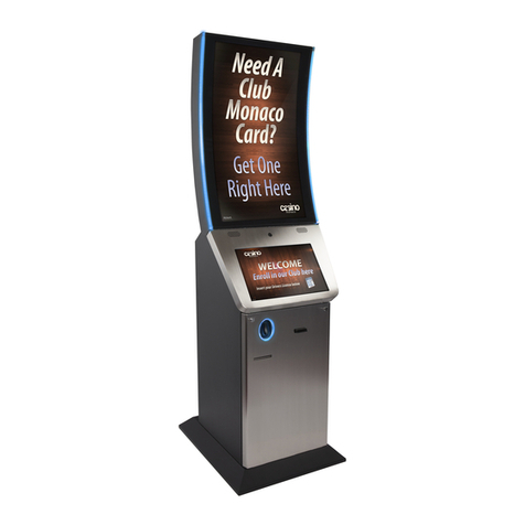
21.5” Hospital Kiosk System
KT-7290 S2

KT-7290 Hospital Kiosk System
with P-Cap Touch
COPYRIGHT NOTICE & TRADEMARK
All trademarks and registered trademarks mentioned herein are the
property of their respective owners.
This manual is copyrighted in May 2020. You may not reproduce or
transmit in any form or by any means, electronic, or mechanical,
including photocopying and recording.
DISCLAIMER
This service manual is meant to assist servicing engineers in
disassembling the system. The information contained in this document
is subject to change without any notice.
CE NOTICE
This is a class A product. In a domestic environment this product may
cause radio interference in which case the user may be required to take
adequate measures.

FCC NOTICE
This equipment has been tested and found to comply with the limits for
a Class A digital device, pursuant to part 15 of the FCC Rules. These
limits are designed to provide reasonable protection against harmful
interference when the equipment is operated in a commercial
environment. This equipment generates, uses, and can radiate radio
frequency energy and, if not installed and used in accordance with the
instruction manual, may cause harmful interference to radio
communications. Operation of this equipment in a residential area is
likely to cause harmful interference in which case the user will be
required to correct the interference at his own expense.
You are cautioned that any change or modifications to the equipment
not expressly approve by the party responsible for compliance could
void your authority to operate such equipment.
CAUTION: Danger of explosion may occur when the battery
is incorrectly replaced. Replace the battery
only with the
same or equivalent type recommended by the manufacture
r.
Dispose of used batteries according to the manufacturer’s
instructions.
WARNING: Some internal parts of the system may have high
electrical voltage. We strongly recommend that only qualified
engineers are allowed to service
and disassemble the
system. If any damages should occur on the system and are
caused by unauthorized servicing, it will not be covered by
the product warranty. Please operate the LCD and
Touchscreen with extra care as they can break easily.
i
Contents
Revision History .............................................................................................iii
1Before You Start .................................................................................. 1-1
1.1 Before You Start ........................................................................ 1-2
1.2 KT-7290 Kiosk System Overview.............................................. 1-2
1.3 Suggested Tools........................................................................ 1-3
2Hardware Replacement ...................................................................... 2-1
2.1 Replacing System Fans ............................................................ 2-3
2.2 Replacing A4 Printer Fan ........................................................ 2-16
2.3 Replacing RFID LED Module .................................................. 2-29
2.4 Replacing OCR1 LED Module ................................................2-38
2.5 Replacing OCR2 LED Module ................................................2-47
2.6 Replacing A4 Printer Cable ..................................................... 2-56
2.7 Replacing A4 Printer Tray ....................................................... 2-78
2.8 Replacing A4 Printer IR Sensor .............................................. 2-95
2.9 Installing A4 Printer Cover..................................................... 2-100
2.10 Replacing Thermal Printer Cable ..........................................2-107
2.11 Replacing Green LED Cable................................................. 2-131
2.12 Replacing Red LED Cable ....................................................2-148
2.13 Replacing Speaker Module ...................................................2-164
2.14 Replacing Power Adapter for Main Board............................. 2-170
2.15 Replacing Power Adapter for KR-7230 Daughter Board ......2-176

ii
2.16 Replacing Face Camera .......................................................2-186
2.17 Replacing Thermal Camera .................................................. 2-195
2.18 Installing Human IR Sensor ..................................................2-205
2.19 Replacing Bluetooth Module .................................................2-208
2.20 Replacing LCD AD Board...................................................... 2-215
2.21 Replacing Ethernet Switch .................................................... 2-221
2.22 Replacing LCD Panel............................................................2-229
2.23 Replacing Thermal Printer Board..........................................2-243
2.24 Replacing Thermal Printer Sensor ........................................ 2-254
2.25 Replacing Touch Panel ......................................................... 2-263
2.26 Replacing Thermal Printer Module........................................ 2-284
2.27 Replacing Bluetooth Antenna................................................2-305
2.28 Replacing OCR X50 Scanner Module .................................. 2-309
2.29 Replacing Barcode Scanner .................................................2-320
2.30 Replacing Power Extension Socket ...................................... 2-329
2.31 Replacing SSD (Solid-State Drive)........................................2-342
2.32 Replacing RAM ..................................................................... 2-349
2.33 Replacing KR-7130 Daughter Board ....................................2-355
2.34 Replacing KR-7230 Daughter Board ....................................2-362
2.35 Replacing PB-6722 Main Board............................................ 2-369
2.36 Installing MSR Module from the Side.................................... 2-382
2.37 Installing MSR Module from the Front...................................2-387

iii
Revision History
The revision history of KT-7290 Service Manual is described below:
Version No.
Revision History
Page No.
Date
S2 Added “Replacing A4 Printer
Tray” section.
2-78 ~ 2-94 2020/5/7
Added “Installing A4 Printer IR
Sensor” section.
2-95 ~ 2-99
Adding “Installing A4 Printer
Cover” section.
2-100 ~ 2-106
Added “Installing Human IR
Sensor” section and remove
the “Replacing IR Sensor”
section in S1 version.
2-205 ~ 2-207
Modified the section of
“Replacing KR-7130 Daughter
Board”.
2-355 ~ 2-361
Added the section of “Installing
MSR Module from the Front”.
2-387 ~ 2-393
S1
Initial Release
-
2019/2/27

KT-7290 SERIES SERVICE MANUAL
Page: 1-1
1 Before You Start
This chapter provides the information that you should be
cautioned before you proceed to remove the components
and integrated devices of KT-7290 system.
The following topics are included:
•Before You Start
•KT-7290 Kiosk System Overview
•Suggested Tools

Chapter 1 Before You Start
KT-7290 SERIES SERVICE MANUAL
Page: 1-2
1.1 Before You Start
It is highly recommended that you heed the following servicing precautions
before you start to disassemble the KT-7290 kiosk system:
1Unplug the AC Power cord to remove the power supply for the KT-7290
kiosk system before you start to remove the system devices or
components.
2Please strictly follow the hardware device replacement sequence
specified in the service manual while you service the KT-7290 kiosk
system.
WARNING: Please read and follow the instructions
described in this service manual carefully while you are
disassembling the LCD display and all the integrated
devices. If any damages should occur on the system
and are caused by inappropriate servicing, it will not be
covered by the system warranty.

Chapter 1 Before You Start
KT-7290 SERIES SERVICE MANUAL
Page: 1-2
1.2 KT-7290 Kiosk System Overview
The appearance of KT-7290 kiosk system is shown below:

Chapter 1 Before You Start
KT-7290 SERIES SERVICE MANUAL
Page: 1-3
1.3 Suggested Tools
Before you start to service KT-7290 kiosk system, it is recommended that you
use the following tools throughout the hardware disassembly and replacement
procedures:
PH2 Screwdriver
7mm Point Socket Screwdriver
5.0mm Point Socket Screwdriver

Chapter 1 Before You Start
KT-7290 SERIES SERVICE MANUAL
Page: 1-4
5.5mm Point Socket Screwdriver
2.0 Screwdriver
2.5 Screwdriver

Chapter 1 Before You Start
KT-7290 SERIES SERVICE MANUAL
Page: 1-5
3.0 Flat Head Screwdriver
Diagonal Cutter (for cutting off cable ties)

KT-7290 SERIES SERVICE MANUAL
Page: 2-1
2 Hardware Replacement
This chapter provides the information on how you can
remove and replace the integrated devices of KT-7290
Kiosk system.
The following topics are included:
•Replacing System Fans
•Replacing A4 Printer Fan
•Replacing RFID LED Module
•Replacing OCR1 LED Module
•Replacing OCR2 LED Module
•Replacing A4 Printer Cable
•Replacing A4 Printer Tray
•Installing A4 Printer IR Sensor
•Installing A4 Printer Cover
•Replacing Thermal Printer Cable
•Replacing Green LED Cable
•Replacing Red LED Cable
•Replacing Speaker Module

Chapter 2 Hardware Disassembly and Replacement
KT-7290 SERIES SERVICE MANUAL
Page: 2-2
•Replacing Power Adapter for Main Board
•Replacing Thermal Camera
•Installing Human IR Sensor
•Replacing Bluetooth Module
•Replacing LCD AD Board
•Replacing Ethernet Switch
•Replacing LCD Panel
•Replacing Thermal Printer Board
•Replacing Thermal Printer Sensor
•Replacing Touch Panel
•Replacing Thermal Printer Module
•Replacing Bluetooth Antenna
•Replacing OCR X50 Scanner Module
•Replacing Barcode Scanner
•Replacing Power Extension Socket
•Replacing SSD (Solid-State Drive)
•Replacing RAM
•Replacing KR-7130 Daughter Board
•Replacing KR-7230 Daughter Board
•Replacing PB-6722 Main Board
•Installing MSR Module

Chapter 2 Hardware Disassembly and Replacement
KT-7290 SERIES SERVICE MANUAL
Page: 2-3
2.1 Replacing System Fans
This section introduces how you can replace the five system fans for KT-7290
kiosk system.
It is recommended that you use the PH2 screwdriver type as below:
Follow the instructions below to remove the 1st system fan:
Step 1. Insert the panel key to unlock the LCD panel.

Chapter 2 Hardware Disassembly and Replacement
KT-7290 SERIES SERVICE MANUAL
Page: 2-4
The 1st system fan (highlighted in yellow) is located on the upper side within
the LCD panel. See the picture below:

Chapter 2 Hardware Disassembly and Replacement
KT-7290 SERIES SERVICE MANUAL
Page: 2-5
Step 2. Remove the 4 screws of the 1st system fan cover.

Chapter 2 Hardware Disassembly and Replacement
KT-7290 SERIES SERVICE MANUAL
Page: 2-6
The 1st system fan can be seen after the 4 screws are removed.
The connection of the system fan cable can be found on the lower-left below
the 1st system fan. Please see the picture below:

Chapter 2 Hardware Disassembly and Replacement
KT-7290 SERIES SERVICE MANUAL
Page: 2-7
Step 3. Unplug the fan cable from the 1st system fan connector.
Step 4. Remove the 1st system fan and replace with a new one.

Chapter 2 Hardware Disassembly and Replacement
KT-7290 SERIES SERVICE MANUAL
Page: 2-8
Step 5. Connect the fan cable onto the system fan connector properly. Note
that the pin connection must be accurate.
Step 6. Tighten the 4 screws of the 1st system fan cover.
Table of contents
Other protech Digital Signage manuals

protech
protech PA-1822 User manual

protech
protech KS-M320 User manual

protech
protech KF-7131 User manual

protech
protech KS-M331 User manual

protech
protech KS-1130 User manual

protech
protech prox SP-C085 User manual

protech
protech prox KF-P230 User manual

protech
protech prox KF-P230 User manual

protech
protech prox KS-M220 User manual

protech
protech MD-591X User manual