Clavia Nord Drum 2 User manual

User Manual
Nord Drum 2
OS version 2.1x
Part No. 50416 Copyright Clavia DMI AB
Print Edition: B

CAUTION - ATTENTION
RISK OF ELECTRIC SHOCK
DO NOT OPEN
RISQUE DE SHOCK ELECTRIQUE
NE PAS OUVRIR
CAUTION: TO REDUCE THE RISK OF ELECTRIC SHOCK
DO NOT REMOVE COVER (OR BACK).
NO USER SERVICEABLE PARTS INSIDE.
REFER SERVICING TO QUALIFIED PERSONNEL.
ATTENTION:POUR EVITER LES RISQUES DE CHOC ELECTRIQUE, NE
PAS ENLEVER LE COUVERCLE.
AUCUN ENTRETIEN DE PIECES INTERIEURES PAR L´USAGER.
CONFIER L´ENTRETIEN AU PERSONNEL QUALIFE.
AVIS: POUR EVITER LES RISQUES D´INCIDENTE OU D´ELECTROCUTION,
N´EXPOSEZ PAS CET ARTICLE A LA PLUIE OU L´HUMIDITET.
1) Read these instructions.
2) Keep these instructions.
3) Heed all warnings.
4) Follow all instructions.
5) Do not use this apparatus near water.
6) Clean only with dry cloth.
7) Do not block any ventilation openings. Install in accordance
with the manufacturer’s instructions.
8) Do not install near any heat sources such as radiators, heat
registers, stoves, or other apparatus (including ampliers) that
produce heat.
9) Do not defeat the safety purpose of the polarized or
grounding-type plug. A polarized plug has two blades with one
wider than the other. A grounding type plug has two blades
and a third grounding prong. The wide blade or the third prong
are provided for your safety. If the provided plug does not t
into your outlet, consult an electrician for replacement of the
obsolete outlet.
10) Protect the power cord from being walked on or pinched
particularly at plugs, convenience receptacles, and the point
where they exit from the apparatus.
11) Only use attachments/accessories specied by the manu-
facturer.
12) Use only with the cart, stand,
tripod, bracket, or table specied by the
manufacturer, or sold with the apparatus.
When a cart is used, use caution when
moving the cart/apparatus combination to
avoid injury from tip-over.
13) Unplug this apparatus during lightning
storms or when unused for long periods of time.
14) Refer all servicing to qualied service personnel. Servicing
is required when the apparatus has been damaged in any way,
such as power-supply cord or plug is damaged, liquid has been
spilled or objects have fallen into the apparatus, the apparatus
has been exposed to rain or moisture, does not operate nor-
mally, or has been dropped.
The lightning ash with the arrowhead symbol within
an equilateral triangle is intended to alert the user to the
presence of uninsulated voltage within the products en-
closure that may be of sufcient magnitude to constitute
a risk of electric shock to persons.
Le symbole éclair avec le point de èche à l´intérieur d´un triangle
équilatéral est utilisé pour alerter l´utilisateur de la presence à
l´intérieur du coffret de ”voltage dangereux” non isolé d´ampleur
sufsante pour constituer un risque d`éléctrocution.
The exclamation mark within an equilateral triangle is
intended to alert the user to the presence of important
operating and maintenance (servicing) instructions in the
literature accompanying the product.
Le point d´exclamation à l´intérieur d´un triangle équilatéral est
employé pour alerter l´utilisateur de la présence d´instructions
importantes pour le fonctionnement et l´entretien (service) dans le
livret d´instructions accompagnant l´appareil.
Instructions pertaining to a risk of re, electric shock or injury to persons.
IMPORTANT SAFETY INSTRUCTIONS
SAVE THESE INSTRUCTIONS
Trademarks: The Nord logo is trademark of Clavia DMI AB. All other trademarks mentioned
in this publication are the properties of their respective holders.
Specications and appearances are subject to change without notice.
Copyright © Clavia DMI AB
No naked ame sources, such as lighted candles, should be placed on
the apparatus;
Do not use the apparatus in tropical climates.
WARNING: To reduce the risk of re or electric shock, do not expose
this apparatus to rain or moisture.
The apparatus shall not be exposed to dripping or splashing and that
no objects lled with liquids, such as vases, shall be placed on the
apparatus.
The maims plug is used as the disconnect device and shall remain
readily operable.
Il convient de ne pas placer sur l´appareil de sources de ammes nues,
telles que des bougies allumées;
L´appareil n’est pas destiné á étre utilisé sous un climat tropical.
L´appareil ne doit pas étre exposé á des égouttements d´eau ou des
éclaboussures et de plus qu´aucun objet rempli de liquide tel que des
vases ne doit étre placé sur l´appareil.
Lorsque la prise du résau d’alimentation est utilisée comme dispositif
de déconnexion, ce dispositif doit demeuré aisément accessible.
Warning - When using electric products, basic precautions should always be followed, including the following:
Additional Safety Information

1 Overview
Thank you! .................... 4
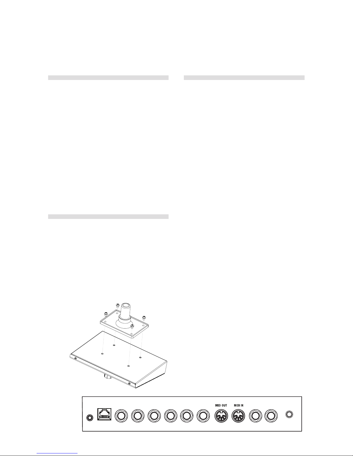
Attaching the stand holder.... 4
Connections ................... 4
Phones ......................... 4
Left, Right Out.................... 4
MIDI In .......................... 4
MIDI Out ........................ 4
Trig Inputs CH 1 – CH 6 ............ 5
Power .......................... 5
Parameter names.............. 6
The Panel ..................... 6
Channel Select ................... 6
Input Trig Level LEDs . . . . . . . . . . . . . . 7
Peak/Focus LEDs ................. 7
Trig/Mute Group LEDs ............. 7
Lower Param..................... 7
Dial ............................ 7
Shift/Exit ....................... 7
Solo Edit ........................ 8
Trig/ Tap ........................ 8
Trig Level ........................ 8
Program ........................ 8
2 Getting Started
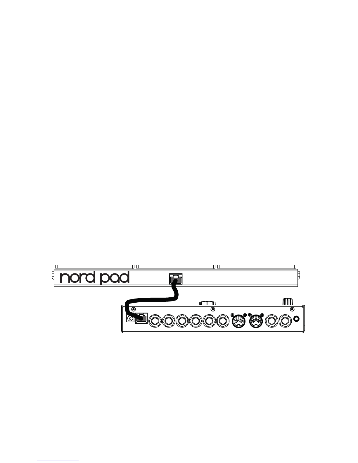
Connect a Nord Pad ........... 9
Connecting pads............... 9
Adjust Input sensitivity ....... 9
Threshold......................10
Nord Pad - Inp Sens & Thres .10
MIDI Channel ..................10
MIDI Note assignment.........10
MIDI Note Learn ...............11
Changing programs ...........11
Play the Demo.................12
Memory Protect ...............12
Storing.........................12
3 Reference
Channels & signal flow .......13
The Parameters ...............13
Master Level .....................13
Store ...........................13
Program/Value LED display .........13
Mute Group .....................14
Edit Group ......................14
Edit Group Paste ..................14
Noise Parameters .............14
Filter Freq .......................14
Filt Type .........................14
Filter Env (Dyn Filter) ...............15
Filt Res .........................16
Attack/Rate (Atk/Rate) .............16
Atk Mode (Env Mode) ..............16
Decay ..........................17
Dec Lo (Type/Dyn).................17
Tone Parameters ..............18
Spectra .........................18
Wave ...........................18
Timb Env (Dyn Timb) ...............18
Timbre..........................19
Timb Dec (Hi Decay) ...............19
Punch ..........................19
Decay ..........................19
Dec Lo (Type/Dyn) ............... 20
Pitch .......................... 20
Scl Pre......................... 20
Bend .......................... 20
Bend Time.......................21
Click Parameters ..............21
Level ...........................21
Type............................21
Mix Parameter ................21
Channel Parameters . . . . . . . . . .21
Distort ..........................21
Distortion Type .................. 22
Eq Freq ........................ 22
Gain........................... 22
Echo (Repeat) ................... 22
Echo (Repeat) Amount ............ 22
Echo BPM (Repeat Tempo) ........ 22
Level .......................... 22
Pan ........................... 22
Global Settings .............. 22
Copy .......................... 23
Paste ......................... 23
Sound Init ...................... 23
Panic ......................... 23
System ........................ 23
MIDI .......................... 23
Trig Type ........................24
Inp Thres ...................... 25
Inp Sens, Dynamics .............. 25
Updating the OS.............. 26
Website ........................ 26
4 Nord Drum 2 Manager
MIDI Interface ....................27
Get Banks .......................27
Send Banks......................27
5 MIDI
MIDI Operation . . . . . . . . . . . . . . . 28
Global & Individual MIDI ........... 28
Global MIDI Channel .............. 28
Individual MIDI Channels........... 28
Recording: Global MIDI Ch. .. 28
Recording parameter changes ...... 28
Recording: Indiv. MIDI Ch. ... 29
Pitch control on Individual MIDI Ch. .. 29
MIDI Controller ............... 29
Nord Beat..................... 30
Storing the memory content . 30
Receive Sys Ex Data.......... 30
MIDI CC Numbers..............31
MIDI Implementation Chart .. 32
6 Appendix
Stand setup .................. 33
7 Index
Stand setup .................. 34
Nord Drum 2 - Table of Contents

4 | Nord drum 2 user maNual os v2.1x
Chapter 1 overview | 5
Thank you!
Thank you for purchasing the Nord Drum 2.
We have designed this musical instrument to
be a one of a kind drum synthesizer for drum-
mers, percussionists and producers, seeking
unique and playable percussive sounds.
You are probably eager to start using the
Nord Drum 2 right away, but please spend
a few minutes with the first pages of this
manual. This will give you a good start on
how to hook it up, and to access the amaz-
ing features.
Attaching the stand
holder
The stand holder is used to mount the Nord
Drum 2 on a stand that is equipped with a
clamp. The diameter is 23 millimeter (0.9
inches) which will fit most general purpose
clamps.
Connections
Phones
Connect a low impedance stereo headphone
to the Phones output. This is a 1/8" (mini)
jack.
Left, Right Out
The L and R outputs are unbalanced ¼"
jacks with line level signals.
EThe Nord Drum 2 is capable of produc-
ing sounds with a very wide dynamic and
frequency range. Be careful when you use
the unit and when you edit the sounds.
MIDI In
Connect the MIDI Input to a drum pad or a
sequencer if you want to control the Nord
Drum 2 with incoming MIDI messages. The
MIDI Input is also used when you update the
unit with new operating systems.
MIDI Out
Connect the MIDI Output to a computer or
sequencer to record what’s played on the
Nord Pad or other pads connected to the Trig
Inputs. The performance will be transmitted
as MIDI notes, which also can be used to
trigger other MIDI units.
MIDI Output is used with the Program Dump
feature to transfer the settings of the
programs in the Nord Drum 2 via MIDI.
LEFT OUT
CH 1CH2CH 3CH 4
CH 4
POWER CH 5
CH 6
NORD PAD INPUT
RIGHT OUT PHONES
1 Overview

Chapter 1 overview
| 5
Trig Inputs CH 1 – CH 6
Connect drum pads or other signal sources
to the Trig Input ¼" jacks. These inputs can
be used with a variety of different signals. The
sensitivity and the threshold of the inputs can
be adjusted with the Inp Sens and Inp Thres
parameters, read more about this in the fol-
lowing chapter.
EDo not connect pads while the Nord Drum
2 is turned on, this will trigger the sounds.
The Nord Drum 2 has been developed and
tested with different pad and trigger types.
The Trig Inputs are designed to be very ver-
satile and is compatible with many different
types of signals.
MIf you experience double triggered
sounds, flams or a slow response from
the Nord Drum 2, make sure that you ad-
just the Trig Type, Inp Thres and Inp Sens
parameters. Read more on how to adjust
these settings on page 9
Power
Connect the Nord Drum 2 power supply to
the Power input. If the original supply is not
available, use only a 12 volt DC, 250 mA
adapter, with a barrel type plug that has the
positive current on the tip. The outer diameter
of the plug is 5.5 millimeter and the inner
diameter is 2.1 millimeter.
EAlways turn on the Nord Drum 2 first and
the sound system last, and reverse this
order when you want to turn it off again.
Nord Pad Input
Connect a Nord Pad to the RJ45 connector,
using the CAT6 cable that is supplied with the
Nord Pad.
EThis connection can not be used with any
other equipment. Do not try and connect
a computer network or any other RJ45
equipped unit to the Nord Drum 2.

6 | Nord drum 2 user maNual os v2.1x
Chapter 1 overview | 7
Parameter names
Please note: Some parameters on the Nord
Drum 2 panel have had their names changed
since the release of version 2.1. This manual
will use the new names in the text and illus-
trations but the old names will be included in
(round brackets).
Old name New name
Dyn Filter Filt Env
Atk/Rate Attack/Rate
Env Mode Atk Mode
Type/Dyn (Noise) Dec Lo
Repeat Echo
Dyn Timb Timb Env
Hi Decay Timb Dec
Type/Dyn (Tone) Dec Lo
Trig (Button) Trig/Tap
Repeat Tempo Echo BPM
The Panel
The buttons, the LED display and the Dial are
used when you select a program and when
you edit the sounds in the Nord Drum 2.
Channel Select
There are six channels, each channel repre-
sents one sound. Press the Channel Select
buttons repeatedly to change and select
the channel to be triggered with the Trig/Tap
button on the panel and/or to be edited. The
red Focus LEDs will indicate which channel is
selected and will stay lit when you are editing
a sound.
You can use pads to quickly select the
channel to edit, if no channel has been
previously selected with a Channel Select
button. If a Channel Select button has
been used to manually select a channel,
press the Program button once, strike
a pad to select the channel and then a
parameter button to return to editing that
channel.

Chapter 1 overview
| 7
Input Trig Level LEDs
The Input LEDs are used to indicate channel
activity, if a channel is triggered, being edited
or part of a Mute or Edit Group. Read more
about Groups on page 14.
Peak/Focus LEDs
The upper red LEDs will flash when a trigger
input receives a signal from the pad or trigger
device. This indication can be used to make
sure that you utilize the full dynamic range of
the Nord Drum 2. The red Peak LED should
be lit with a longer duration when you play
with your maximum force. If it blinks (which
it does 3 dB below the maximum), you can
increase the Input Sensitivity, see page 9.
EThe red LEDs do not indicate overload or
distortion in the audio signal path of the
Nord Drum 2.
Trig/Mute Group LEDs
The lower green LEDs will blink on channel
activity. Solid green LEDs indicates which
channels are in the Mute Group.
Parameters are accessed with the row of
eight buttons. Press one of the buttons to
begin to edit a sound. Settings are changed
when the Dial is turned.
If a button activates a parameter in the up-
per row, a quick double-tap on the same
button or by pressing the Row Select button
will move the edit focus to the second row
parameter.
Lower Param
When you want to see the setting of, or edit
one of the parameters with the red labels,
hold down the “Lower
Param” button. Another
method is to hold down
that particular parameter
button.
Dial
Turn the Dial to select
programs and to change
the setting of a selected
parameter when you are
editing a sound.
The Dial is sensitive to the
speed of the turning action. A quick twist to
the left or the right can set a parameter to its
lowest or highest value.
Certain parameters have a basic setting in
the middle between the highest and lowest
settings, Bend is one of these with 0 Bend in
the middle of the range. Twist the Dial quickly
and the setting will make a stop in this center
setting.
Shift/Exit
The Shift button is
used together with
the buttons to access
additional parameters.
These additional pa-
rameters are labeled with the text below the
buttons.
The System, MIDI and Inp Sens param-
eters have more than one setting. These
are accessed by pressing repeatedly on the
buttons.

8 | Nord drum 2 user maNual os v2.1x
Chapter 1 overview | 8
Press the Shift button to exit a store opera-
tion, or to exit editing the additional param-
eters.
Solo Edit
Solo Edit allows you to hear only the section
(Noise, Tone or Click) that is
currently being edited. In
addition, the channel in
focus will be soloed in
regard to incoming MIDI
notes.
Trig/Tap
Trig: Use the Trig/Tap (Trig)
button to trigger a selected
channel.
Tap: You can set the Echo
tempo by tapping. Hold the
Shift and Echo BPM button, and tap repeat-
edly on the Trig/Tap (Trig) button. Four taps
are needed to set a tempo. Dots in the lower
part of the LED display will show the progress
of the beats as you tap.
Trig Level
Adjust the Trig/Tap button’s output velocity.
Range: 1 - 20
Program
Press the Program button to the left of the
display to return to selecting programs with
the Dial.

Chapter 2 GettiNG started
| 9
Connect a Nord Pad
1 Use the supplied CAT6 cable to connect
a Nord Pad to the Nord Pad Input on the
Nord Drum.
If you want to add a kick drum pad to the
Nord Drum 2 while using the Nord Pad,
connect the kick pad to the CH 1 input.
The other inputs are disabled when the
Nord Pad is connected.
Connecting pads
1 Connect your pads to the six Trig Inputs
on the Nord Drum 2.
Most of the factory sounds use Channel
1 for Bass drum, channel 2 for Snare and
channel 3 to 6 for toms.
Adjust Input sensitivity
It is important to adjust the Input Sensitivity,
to be able to use the full dynamic range of the
Nord Drum 2.
1 Strike the pad, listen to the sound from
the Nord Drum 2 and look at the Input
Channel LEDs for that particular chan-
nel. The LEDs indicate the strength of
the incoming trigger signal from the pad.
2 Hold Shift and press the Inp Sens button
on the Nord Drum 2 panel. The LED
above the Inp Sens button will flash to
indicate that your are editing System
parameters
3 The red Peak/Focus LEDs will indicate
the trigger strength with a quick flash
when the trigger signal strength is
“almost there” and with a longer flash
when you have correctly matched the
input sensitivity with your strongest
force.
4 Press the Channel Select button to
move the solid green LED to the channel
that the pad you are striking is con-
nected to.
5 Strike the pad and adjust the Input sen-
sitivity with the Dial to match the input
sensitivity, the pad response and your
striking force.
6 Repeat steps 3 to 5 for the other pads.
LEFT OUT
CH 1CH2CH 3CH 4
CH 5
RIGHT OUT PHONES
2 Getting Started

10 | Nord drum 2 user maNual os v2.1x
Chapter 2 GettiNG started | 11
Threshold
If you have pads or other pieces in your kit
that are mounted on the same hardware,
you can use the Input Threshold (Inp Thres)
parameter to eliminate any unwanted, ac-
cidental triggers.
1 Hold Shift and press the Inp Thres but-
ton.
2 Select the Nord Drum 2 Channel that is
responding to the unwanted trigger.
3 Strike the pad or drum that causes the
unwanted triggers and raise the Inp
Thres value with the Dial until the Nord
Drum 2 channel stops triggering.
4 Strike the pad that should properly trig-
ger the Nord Drum 2 to verify that the
new setting has not changed the desired
response.
Nord Pad - Inp Sens &
Threshold
When a Nord Pad is connected to the Nord
Drum 2, the Inp Sens and Thres parameters
are not individually adjusted for each channel/
pad, only one Inp Sens and one Thres setting
will be used.
If you add a kick drum pad to the CH1 Trig
Input, this channel can however be adjusted
separately.
MIDI Channel
If you wish to control the Nord Drum 2 with a
MIDI unit, the MIDI channel and the notes that
this unit transmits must be matched to the
MIDI channel of the Nord Drum 2. The default
Global MIDI Channel is channel 10.
1 Connect a MIDI pad or other MIDI
controller to the MIDI Input on the Nord
Drum 2.
2 Hold Shift and press the MIDI button
repeatedly to access the “ L” (Global)
setting.
MThe LED above the MIDI button will flash
to indicate that your are editing System
parameters.
3 Turn the Dial to select the MIDI channel
you wish the Nord Drum 2 to use.
MIDI Note assignment
When the Nord Drum 2 is shipped from the
factory, channels 1 to 6 are assigned to MIDI
note numbers: 60, 62, 64, 65, 67 and 69.
Here is how to change this:
1 Connect a MIDI pad or other MIDI
controller to the MIDI Input on the Nord
Drum 2.
2 Hold Shift and press the MIDI button
repeatedly until you see a “n” followed
by a number in the display.
3 Press the Channel Select buttons on
the Nord Drum 2 to select one of the
channels.
4 Turn the Dial to set the desired MIDI
Note Number for that channel.
5 Repeat steps 3 and 4 to assign the other
channels to the MIDI note numbers that
the MIDI unit transmits.
6 Press the Program button to exit.

Chapter 2 GettiNG started
| 11
MIDI Note Learn
If you wish to control the Nord Drum 2 with
a MIDI controller, the MIDI notes that this
controller transmits can be automatically as-
signed by the Nord Drum 2 to trigger the six
channels.
1 Connect a MIDI pad or other MIDI
controller to the MIDI Input on the Nord
Drum 2.
2 Press Channel Select on the Nord Drum
2 to select one of the channels.
3 Press MIDI repeatedly until “n” is shown
in the display. Turn the dial until you
reach the setting after 127, “Lrn”.
4 Strike the pad on the MIDI unit that you
wish to assign to the selected Nord
Drum 2 channel.
The note number that the MIDI pad
transmitted will be assigned to this Nord
Drum 2 channel and will be shown in the
display.
5 Repeat steps 2, 3 and 4 to assign the
other five channels to the additional
MIDI note numbers that the MIDI unit
transmits.
6 Press the Program button to Exit.
Changing programs
Press the Program button and turn the dial to
change programs. Programs are organized in
8 Banks with 50 Programs in each bank.
Hold Shift and
turn the Dial
to change the
Bank number.
The Nord Drum 2 memory is divided into 8
banks with 50 user definable programs each
(400 in total).
When shipped from the factory, the Nord
Drum 2 comes with a selection of sounds
organized in the following way:
Bank Drums
1 Drum Kits & Machines
2 Drum Kits & Machines
3 Tuned Perc, Marimba, Xylofon
4 Fantasy
5 Free
6 Free
7 Free
8 Free
All the sounds can be edited and overwritten
if you like, or saved as copies to other loca-
tions. The P5 to P8 banks are intentionally
left blank for saving your own creations but
you’re free to save anywhere you like.
The factory banks are available at the
www.norddrum.com website, if you wish
to restore the unit to the factory settings

12 | Nord drum 2 user maNual os v2.1x
Chapter 2 GettiNG started | 12
Play the Demo
1 Press the Program, Channel Select and
Trig buttons simultaneously to start the
Demo playback.
2 Turn the Dial while the demo is playing
to listen to the various sounds in the
Factory soundbank.
3 Press Shift/Exit to stop the playback.
Memory Protect
When the Nord Drum 2 is shipped from the
factory, storing programs to the memory is
not possible until you turn the Memory pro-
tection off. This is one of the System settings.
MIf the Memory Protect is On, the display
will show “PrOt” when you try to Store a
program.
1 Hold Shift and press repeatedly on the
System button until “Pr.On” is shown in
the display.
2 Turn the Dial to the “Pr.Of” setting.
This makes it possible to store programs
until this parameter is set to On again.
3 Exit by pressing the Program button.
Storing
When a program has been edited, this is
indicated with a dot to the right of the
program number.
If you select
another program,
your edits will be
lost. If you want to
keep any changes
you have made, you have to Store the edited
program.
1 Hold Shift and press the Program/Store
button.
2 The display will start to blink.
3 Select a location for the new program
with the dial.
If a selected location is empty, the dot to
the right will light up.
4 Press Program/Store again.
If you do step 4 without turning the Dial,
the edited program will be stored to the
current location.

Chapter 3 refereNCe
| 13
The Parameters
Master Level
The Master Level set the
overall output level of the
Nord Drum 2. This is not a
programmable control.
Store
This function is used when you
store a program in the Nord
Drum 2 memory.
Program/Value LED display
Programs are
indicated in the
display with a P,
followed by
numbers. The first
number is the bank, the second number is
the program.
Edit is enabled
as soon as a
parameter in the
Nord Drum 2 is
selected with a
parameter button.
The presentation of the parameter settings
are made with numbers and/or characters in
the display.
3 Reference
Channels & signal
flow
There are six channels in the Nord Drum 2, it
can produce six simultaneous sounds. Each
one of the channels has an identical set of
parameters. The illustration below shows the
signal flow in the Nord Drum 2.
A sound in the Nord Drum 2 is created with
a blend of up to three components: Tone,
Noise and Click. Each one of these compo-
nents has their individual set of parameters
The Tone can be described as the “body”
of the sound, the Noise is a non-pitched
addition and the Click is the very first tran-
sient, like the contact sound of the stick on
whatever you are hitting. These components
can be processed with effects, such as the
equalizer and an echo effect.

14 | Nord drum 2 user maNual os v2.1x
Chapter 3 refereNCe | 15
Mute Group
The Mute Group feature al-
lows you to mute the output
of one channel/sound by
playing on any other chan-
nel in the Mute Group. This can be used to
silence an open hihat sound on one channel,
by playing a closed hihat sound on another
channel that is in the Mute Group.
Use the Mute Group button (hold Shift and
press) to select a channel as part of the
Mute Group. Select another channel with
the Channel Select buttons and press Mute
Group again to add this to the Mute Group.
The channels in the Mute Group will be
indicated by steady lit green LEDs. The Mute
Group selection will be saved in a Program.
Hold Shift and the Mute Group button for
one second to clear the Mute Group if
there is a selection, or to add ALL chan-
nels to a group if none is selected.
Edit Group
The Edit Group feature allows
you to change the setting of
parameters on all the channels
in the group.
The right Channel Select button allows you
to add/select several consecutive channels
as an Edit Group. The selection begins with
the current channel in focus and adds one
or more to the right of it depending on how
many times you push the button.
An Edit Group is needed for the Scale Preset
feature. Read more about this on page 20.
MEdit groups are not saved as part of
programs.
Hold Shift and the Edit Group button for
one second to clear the Edit Group if there
is a selection, or to add ALL channels to a
group if none is selected.
Edit Group Paste
When using the Paste function to one chan-
nel in a Group, the content will be pasted to
all the channels in the Edit Group.
Noise Parameters
The Noise sound source is a white noise
generator followed by a dynamic multimode
filter which shapes the noise spectra.
The filter cutoff frequency is controlled from a
velocity modulated A/D envelope generator.
Filter Freq
The Filter Freq is the
cutoff frequency where the
selected filter will begin to
influence the noise. The actual sound that
is produced depends on the filter type, see
below.
Range: 0– 50
Filt Type
There are seven filter types to choose from:
low pass, high pass and band pass with
different slopes. The low pass and high pass
can have a 12 or 24 dB/octave slope, with
an additional 24dB/octave High Cut version
of the high pass filter that also dampens the
high frequencies a bit. The band pass can be
set to 6 or 12 dB/octave.

Chapter 3 refereNCe
| 15
A low pass filter dampens the treble, making
the sound duller.
A high pass cuts the bass frequencies,
making the sound brighter.
The band pass dampens frequencies from
both the treble and the bass, leaving the mid
frequencies unfiltered.
The slope describes how steep the filter will
be at the cut off frequency.
Filter Type: LP12, LP24, bP6, BP12,
HP12, HP24, HPhc
Filter Env (Dyn Filter)
Set the amount of the envelope
that changes the noise filter
together with the velocity.
This parameter is bipolar, a positive setting
will open the filter and a negative setting will
close the filter.
Range: -50 to 50
FILT FREQ
=
FILT RES
=
Low pass filter
18
f c
24 dB/oct
12 dB/oct
0
FILT TYPE
=
FILT TYPE
=
freq
gain(dB)
FILT FREQ
=
FILT RES
=
High pass filter
36
f c
24 dB/oct
12 dB/oct
0FILT TYPE
=
FILT TYPE
=
freq
gain(dB)
FILT FREQ
=
FILT RES
=
Band pass filter
30
f c
0
FILT TYPE
=
FILT TYPE
=
12 dB/oct
6 dB/oct
freq
gain(dB)
max velocity
FILT ENV
=
low velocity
FILTER
=
lter
freq Positive filter envelope
0
time
25
50
max velocity FILTER
=
low velocity
FILT ENV
=
Negative filter envelope
lter
freq
0
time
25
50

16 | Nord drum 2 user maNual os v2.1x
Chapter 3 refereNCe | 17
Filt Res
Resonance is used to emphasize frequencies
around the filter cutoff frequency. This can be
perceived as making the sound thinner or a
bit “nasal”.
Range: 0- 20
Attack/Rate (Atk/Rate)
The Attack setting defines
how much time it will take for
the noise level to go from zero
to the maximum level. If the Attack time is
set to “0”, the noise will instantly reach its full
level. If the attack time is higher it will take a
longer time.
If the Atk Mode parameter is set to any of the
LFO modes, this parameter set the rate of
the LFO.
Range: 0- 50
Atk Mode (Env Mode)
The noise envelope (attack, decay) can be
used in a traditional, one shot behavior (Ad).
In addition, the envelope can be set to a
cyclic behavior and will act as a modulating
LFO with sawtooth, inverted sawtooth and
triangle waveforms (LFO1 to LFO3 ) during
the Noise decay.
FILT TYPE
=
FILT FREQ
=
FILT RES
=
Low pass filter w resonance
18
f c
0
24 dB/oct
freq
gain(dB)
AD mode
ATK MODE
=
ATTACK
=
DECAY
=
lter env/
noise amp
decay timeattack time
0
time
decay time
ATK MODE
=
RATE
=
DECAY
=
lter env/
noise amp
LFO mode
0
time

Chapter 3 refereNCe
| 17
The CLP (Clap) settings add a short reverb
phase after sawtooth cycles, which might be
the thing to create a good clap sound. The
higher the number, the longer the tail.
Range: Ad, LFO1-3, CLP1-9
Decay
The Decay parameter defines
how much time it takes for the
level to drop to zero after the
envelope has reached the maximum level
or during the cyclic repeats. The higher the
value, the longer the noise.
Hold Shift and turn the Dial to quickly
choose between the exponential, linear or
a gated response of the noise envelope
decay.
Range: 0-50E, 0-50L, 0-50
Dec Lo (Type/Dyn)
This parameter can activate a second decay,
which is dynamic and will be gradually
introduced when you use less striking force.
This decay time can be either longer or
shorter than the “original” decay, and shares
the response characteristic of the Decay
parameter.
MAt approx. 25% of the maximum velocity,
the Decay time is fully replaced by the Dec
Lo time.
Range: OFF, 0 - 50
lter env/
noise amp Clap mode w exp decay
reverb phasedecay time
ATK MODE
=
RATE
=
DECAY
=
0
time
lter env/
noise amp Clap mode w gate decay
reverb phasedecay time
ATK MODE
=
RATE
=
DEC AY
=
0
time
Type E Type G
Type L
high velocity
low velocity
DECAY
=
DECAY LO
=
Dynamic decay
12 38
amp
0
time
25
50

18 | Nord drum 2 user maNual os v2.1x
Chapter 3 refereNCe | 19
Tone Parameters
The Tone component can be described as
the body of the sound that can be changed
quite drastically with several parameters.
The Wave parameter is a selection of differ-
ent synthesis models, specifically created
to make the foundations for various drum
sounds.
The Spectra and Timbre parameters changes
the harmonic content of the Waves. In addi-
tion, Timbre can be dynamically controlled
with from a velocity modulated decay enve-
lope by using the Timb Env and Timb Dec
parameters.
Spectra
This powerful parameter
allows you to stretch or tune
the spectral components. With for example
the drumhead models (d1 - d9 Waves) you
can tune the head separated from the body
resonance. Very good for making Ethnic type
drum sounds.
When FM is used, the Spectra parameter will
set the modulator frequency.
MSpectra is not available if any the A type
(analog-style) waveforms are selected.
Range: 0 - 99
When Spectra is selected, both the Spec-
tra and the Wave parameter settings will
be shown in the display.
Wave
There are several different synthesis models
called Waves in the Nord Drum 2, each with
its own characteristic. Some have distinctive
pitches, others are of a more non-pitched
variety.
Wave Description
A1 - A4 Analog style waveforms:
Sine, Triangle, Sawtooth and
Square.
F1 - F6 FM algorithms.
H1 - H7 Modelling with harmonic
resonances.
P1 - P4 Resonance modelling of
tuned percussion: marimba,
vibraphone etc.
d1 - d9 Drum head resonance model-
ling.
C1 - C3 Cymbals.
The six FM algorithms are variations on the
synthesis method where one or several oscil-
lators called modulators, modulate the carrier
oscillator(s), creating quite complex wave-
forms. The complexity of the FM algorithms
span from one set of modulator/carrier in F1,
to several in F6.
Range: 0 - 50
Timb Env (Dyn Timb)
Sets the amount of the enve-
lope that changes the Timbre
together with the velocity.
high velocity
DECAY
=
DECAY LO
=
Dynamic decay
low velocity
12 38
amp
0
time
25
50

Chapter 3 refereNCe
| 19
MTimb Env is not available if the A 1 (sine)
waveform is selected.
Timbre
The initial timbre is set with this parameter.
A value of 0 produces less harmonics, and
would allow the Timb Env amount, Timb Dec
and striking force to have a greater influence
on the Wave. A value of 50 will produce the
maximum harmonic content, leaving little to
be controlled by the Timb Env and Timb Dec
parameters.
The analog style waveforms are low pass
filtered, the other Waves will have their har-
monic content changed.
Timbre controls the FM amount if a FM Wave
is selected.
MTimbre is not available if the A 1 (sine)
waveform are selected.
Range: 0 - 50
Timb Dec (Hi Decay)
Timb Decay is the time of the
timbre envelope decay.
MIf the Timb Env parameter is set to 0,
changing this parameter will have no
effect.
MTimb Dec is not available if the A 1 (sine)
waveform is selected.
Range: 0 - 50
Punch
Punch can add a short, velocity controlled
attack portion to the Wave. L1 to L3 indicates
three different levels of this attack.
The “PUP” setting will shift the pitch of the
very first cycle or period in the Wave one
octave up, a great way to get a initial kick in a
bass drum sound. The “Pdn” setting will shift
the pitch of the first period one octave down.
Range: OFF, L1, L2, L3, PUP, Pdn
Decay
The decay parameter sets
the length of the Tone and
the curve of the Tone decay. The higher the
value, the longer the sound.
Hold Shift and turn the Dial to quickly
choose between the exponential or the
linear curve.
Range: 1-50e, 1-50L
max velocity
TIMB ENV
=
low velocity
TIMBRE
=
timbre Timbre control
TIMB DEC
=
timbre decay time
0
time
25
50

20 | Nord drum 2 user maNual os v2.1x
Chapter 3 refereNCe | 21
Dec Lo (Type/Dyn)
This parameter can activate a second
Tone decay, a dynamic decay that will be
introduced when you use less velocity. The
second decay time can be either longer or
shorter than the original decay.
MAt approx. 25% of the maximum velocity,
the Decay time is fully replaced by the Dec
Lo time.
Range: OFF, 0 - 50
Pitch
Set the basic pitch of the
Tone, in semitones. The pitch
is shown in the Display as MIDI Note Num-
bers. A setting of 69.0 equals A = 440 Hz.
Range: 0.0- 127.5
Scl Pre
Use the Scl Pre feature with an Edit Group
to quickly set up different pitch relationships
between pads.
Hold Shift and press the Edit Group button
repeatedly to create an Edit Group. Hold the
SCL Pre button and select a scale with the
Dial.
The pitches will begin at the set pitch on the
lowest numbered channel in the Edit Group
and increase with a factor determined by the
selected scale on the selected channels.
If a Scale has been used to set a pitch
relationship, you can change the pitch of one
channel without breaking the pitch relation-
ship. This will move all the other pitches until
one of the pitches reaches the maximum, or
minimum pitch (“0” or “127.5”).
SCL value Description
Sc.1-10 Pitches are increased by 1,
2, etc. semitones
P 1-3 Pentatonic, P major and
P minor
H 1-5 Hang tunings
Av Hexatonic, augmented
Pr Hexatonic, prometheus
bL Hexatonic, blues
The SCL Pre is not a parameter as such
and will not be stored as one. It will act
as a macro on the pitch settings of the
selected channels.
Bend
The Bend feature bends the
pitch of the Tone. The Bend
has two directions indicated by symbols in
the display, for bending up to the Tone pitch
or for bending down. This parameter is veloc-
ity sensitive.
high velocity
low velocity
DECAY
=
DECAY LO
=
Dynamic decay
12 38
amp
0
time
25
50
high velocity
DECAY
=
DECAY LO
=
Dynamic decay
low velocity
12 38
amp
0
time
25
50
Table of contents
Other Clavia Drum manuals