Clayton DUSTMASTER 660-DM-1000 User manual

TECHNICAL MANUAL
OPERATION AND MAINTENANCE INSTRUCTIONS
DUSTMASTER™
VACUUM SANDING SYSTEMS
660-DM-1000 670-DM-1535-0 670-DM-1535-4 DM-100
DM-104 DM-300 DM-304 682-A100 Cyclone Separator
This manual is intended as a complete operator’s manual for owners and users of the Clayton DustMaster™ Vacuum
Systems. Although this manual details maintenance and operation of Clayton pneumatic tools in conjunction with the
vacuum, these tools are sold separately or as part of a kit. Purchasers of the DustMaster™ vacuum systems may choose
to purchase pneumatic tools, hoses, or accessories from Clayton Associates, Inc.
Clayton Associates, Inc. www.VacuumSanding.com
1650 Oak Street Lakewood, NJ 08701 www.DustlessMadeSimple.com
Phone (732) 363-2100 Fax (732) 364-6084 www.JClayton.com

Copyright © 2012 Clayton Associates Inc.
This page intentionally left blank

Copyright © 2012 Clayton Associates Inc.
Table of Contents
Introduction .....................................................................................................................1
Warnings & Cautions.......................................................................................................2
Preparations....................................................................................................................3
DM-100/300 Operations..................................................................................................4
DM-104/304 Operations..................................................................................................5
Filter Change...................................................................................................................6
Vacuum Maintenance.................................................................................................... 16
Troubleshooting ............................................................................................................17
Warranty........................................................................................................................19

Copyright © 2012 Clayton Associates Inc. 1
Introduction
Clayton Vacuums have been engineered specifically for use in environments where hazardous dust and debris is present.
All operators of this equipment should read this manual thoroughly and understand proper use and maintenance of the
system. The procedures herein provide a method for performing dust and debris collection while minimizing the
particulate contamination of hazardous dust into the air, ground, and water. Failure to follow proper operational
procedures and Safe Filter Change™ instructions can result in personal exposure, damage to equipment, or personal
injury.

Copyright © 2012 Clayton Associates Inc. 2
Warnings and Cautions
When operating electric and pneumatic appliances, or while working nearby one, safety precautions should be exercised
to avoid personal injury and property damage. The following safety precautions should be followed by and communicated
to all personnel working with or around Clayton DustMasterTM Vacuums:
Never exceed compressed air line pressure of 120 PSI. For best results on all Clayton pneumatic vacuums, maintain an
operating pressure of 90 PSI.
Before using this cleaning equipment, check to ensure that all filters are in place. Follow Safe-Filter-Change™
procedures to open filter compartment after initial use.
Never raise cover to filter compartment without the vacuum in operation. The constant suction will prevent
recontamination of the work area and personal exposure to hazardous dust.
This vacuum collection system is intended to collect dry or damp, not wet matter. Free flowing liquids may damage the
ULPA filter, and will void the warranty.
Always store equipment in dry area.
All vacuums must be grounded during operation. Use a conductive air supply hose or attach a grounding wire to
pneumatic vacuums. Always connect electric vacuums to a properly grounded outlet. Failure to use a properly grounded
outlet could result in electrocution, injury, or death.
Never operate an electrical vacuum if the cord appears broken or damaged.
Always use conductive vacuum hoses or vacuum hoses with a static conductive wire and assure that hoses and vacuum
are bonded before use.
Use caution when connecting and disconnecting compressed air lines. When static air pressure is suddenly released, it
can cause the airline to whip.
Never attempt to lift the vacuum system without assistance.
If the vacuum is used with a Clayton Tool Caddy (Model CTK-1 Part No 650-201), always ensure that the CTK-1 is
positioned properly atop the vacuum before moving the system. If the CTK-1 is not properly seated on the vacuum, it can
topple and cause personal injury or property damage.

Copyright © 2012 Clayton Associates Inc. 3
Preparation for Use
System is shipped complete on a pallet. Remove packaging material from around system, and remove any straps or ties
holding the system to the pallet.
If the vacuum is shipped with the optional Clayton CTK-1 (650-201): Lift the CTK-1 up from the vacuum base, and set it
down on the floor.
CAUTION: DO NOT ATTEMPT TO LIFT THE CTK-1 OR THE VACUUM WITHOUT ASSISTANCE. Two persons are
required for lifting.
Lift the vacuum system off the pallet. Casters are already mounted, and filter bags are in place and ready for use.
The electric vacuum is designed to operate on the attached 50’ electrical cord. Do not connect the vacuum to an
extension cord – the added resistance will cause the vacuum to run hot, and performance will be dramatically decreased.
The pneumatic vacuum is designed to operate on a ¾” compressed airline. This size airline will supply enough
compressed air to power the vacuum and up to three pneumatic tools. The vacuum can operate from a ½” airline if no
pneumatic tools are connected. Pneumatic vacuums are shipped with a ¾” compressed air filter in a separate box.
Thread the compressed air filter into the air inlet on the vacuum. Failure to install filter may cause premature motor
failure.
Preparation for Storage
The Clayton DustMasterTM system requires no special preparation for short term storage.
When long term storage is required, Clayton recommends that the operator perform a Safe-Filter-ChangeTM to remove
any dust or residue from the system.
Any pneumatic tools stored with the system should be oiled and operated briefly prior to long-term storage.
Preparation for Shipping
Place the vacuum on a pallet. Support the vacuum on blocks of wood, so that the casters are not against the pallet.
Failure to block the vacuum can cause damage to the caster mounting studs. Strap the vacuum down firmly, ensuring
that it will not be jarred free in shipping.
Shrink wrap or box the pallet.

Copyright © 2012 Clayton Associates Inc. 4
Electric Powered Vacuum Operational Procedures
Ensure that the electrical supply is properly grounded. If unsure, consult a licensed electrician. Connect vacuum power
cord to outlet.
Insert a vacuum hose into one of the vacuum ports. One end of each hose has a metal sleeve – insert this end into the
vacuum port. Connect the end of the airline to one of the three air couplers located between the vacuum ports. This
connection can be made by pushing the airline plug directly into the coupler.
Turn the vacuum control switches to the ON positions. The vacuum will start operation.
If vacuum is used for sanding or grinding, follow the directions below.
Connect the 1/2” air supply to the vacuum air intake, beneath the power switches. Never allow air pressure to exceed 120
PSI.
Connect the vacuum exhaust of the tool to the end of the vacuum hose by threading the cuff onto the hose. Connect the
air fitting on the tool to the airline coupler of the adapter hose.
Choose the proper size of abrasive for the pneumatic tool. If you are unsure of the proper grit abrasive, check with a
supervisor.
CAUTION: Always use a higher-numbered (finer) grit if unsure. Lower numbered (rougher) grits can damage the skin of
some aircraft.
Lay the abrasive onto the backup pad, with the abrasive side facing away from the tool. Ensure that the abrasive sheet
covers the backup pad completely, and that the abrasive is oriented properly. Press the tool against a flat surface with the
abrasive down, to affix the abrasive to the backup pad.
Place the pneumatic tool on the work surface. Keep the abrasive flat against the work surface, and depress the throttle
paddle on the top of the tool. Keep the tool against the work surface at all times while the tool is in motion. Operating a
sander while the abrasive is not touching the work surface can cause the abrasive to spin off of the backup pad.
To control the speed of each tool, locate the speed control valve beneath the tool air intake. Turn the valve control
clockwise to reduce the speed of the tool, and counter clockwise to increase the speed.
If two or three technicians will be operating the system at once, follow the same procedure above using the two remaining
couplers and ports. The air manifold can support up to three airlines. Additional airlines should be hooked directly to the
shop air supply.

Copyright © 2012 Clayton Associates Inc. 5
Air Powered Vacuum Operational Procedures
Below the vacuum control switch is a standard grounding jack, which will accept most aviation grounding plugs. If a
grounding plug is available, connect it to the vacuum. If an aviation grounding plug is unavailable, connect a grounding
clamp to the vacuum.
CAUTION: Failure to properly ground vacuum can result in static buildup and sparking, which could cause fire or
explosion if flammable fumes are present.
Connect the vacuum to an air supply. To operate the vacuum, the air supply must be ½” or larger. To operate the
vacuum and pneumatic tools, the air supply must be ¾” or larger. Air pressure should not exceed 120 PSI.
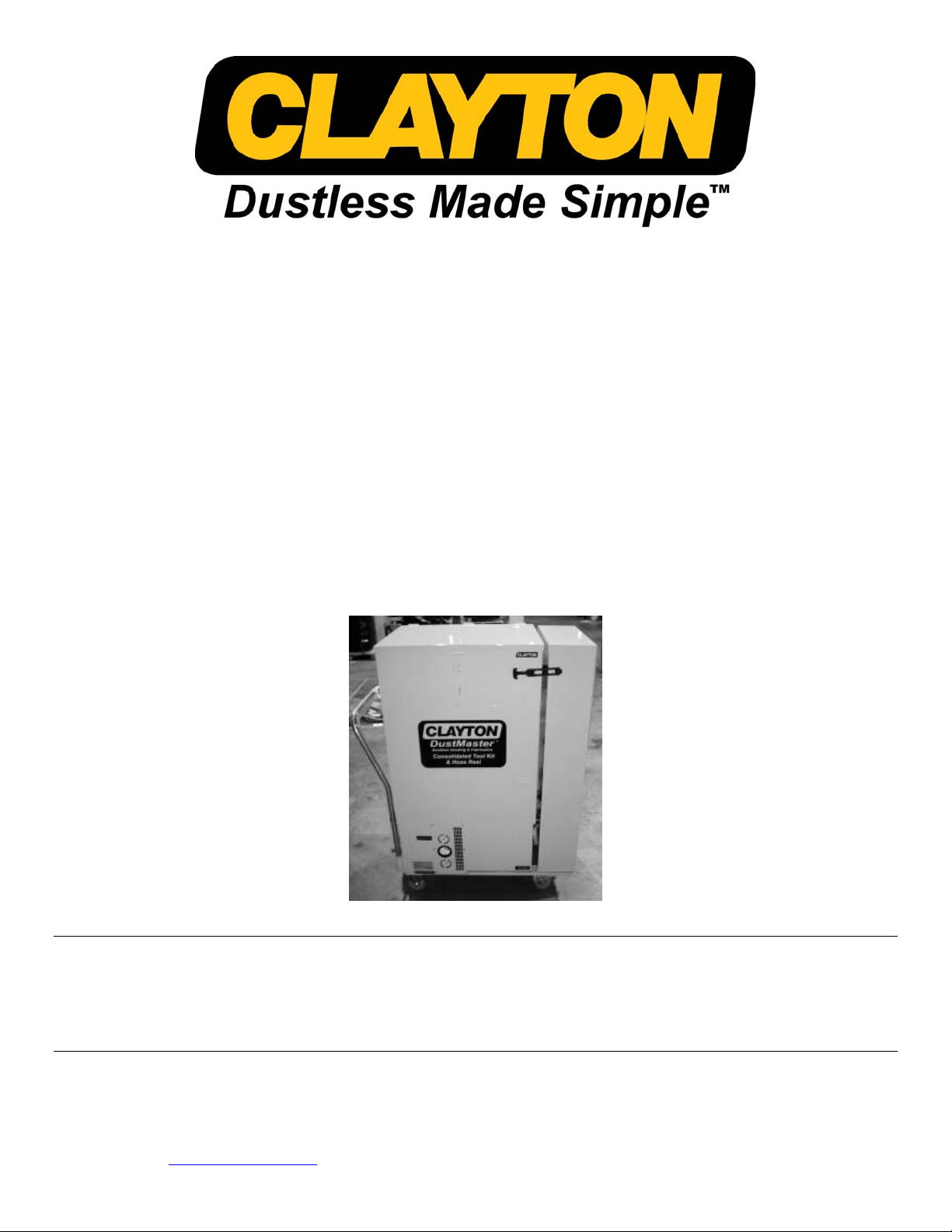
Some models are equipped with an automatic control system, which can be operated in AUTO mode or ON mode. These
vacuums do not have an exposed valve. When the system control is switched to ON, the vacuum will operate
continuously until switched OFF. In AUTO mode, the vacuum will turn ON when a pneumatic tool is actuated, and will
turn off after a brief delay when the pneumatic tool is released.
The time delay for the AUTO system shutoff is user-adjustable. At the bottom of the control panel is the time delay dial.
Turning the dial clockwise will increase the time delay, and turning it counter clockwise will decrease the delay. A
minimum 4-second delay is recommended to allow all dust in hoses to be cleared.
Insert a vacuum hose into one of the vacuum ports. One end of each hose has a metal sleeve – insert this end into the
vacuum port. Connect the end of the airline to one of the three air couplers located between the vacuum ports. This
connection can be made by pushing the airline plug directly into the coupler.
Turn the vacuum control switches to the ON or AUTO position. The vacuum will now be operational.
If vacuum is used for sanding or grinding, follow the directions below.
Connect the 1/2” air supply to the vacuum air intake, beneath the power switches. Never allow air pressure to exceed 120
PSI.
Connect the vacuum exhaust of the tool to the end of the vacuum hose by threading the cuff onto the hose. Connect the
air fitting on the tool to the airline coupler of the adapter hose.
Choose the proper size of abrasive for the pneumatic tool. If you are unsure of the proper grit abrasive, check with a
supervisor.
CAUTION: Always use a higher-numbered (finer) grit if unsure. Lower numbered (rougher) grits can damage the skin of
some aircraft.
Lay the abrasive onto the backup pad, with the abrasive side facing away from the tool. Ensure that the abrasive sheet
covers the backup pad completely, and that the abrasive is oriented properly. Press the tool against a flat surface with the
abrasive down, to affix the abrasive to the backup pad.
Place the pneumatic tool on the work surface. Keep the abrasive flat against the work surface, and depress the throttle
paddle on the top of the tool. Keep the tool against the work surface at all times while the tool is in motion. Operating a
sander while the abrasive is not touching the work surface can cause the abrasive to spin off of the backup pad.
To control the speed of each tool, locate the speed control valve beneath the tool air intake. Turn the valve control
clockwise to reduce the speed of the tool, and counter clockwise to increase the speed.
If two or three technicians will be operating the system at once, follow the same procedure above using the two remaining
couplers and ports. The air manifold can support up to three airlines. Additional airlines should be hooked directly to the
shop air supply.

Copyright © 2012 Clayton Associates Inc. 6
Safe-Filter-Change™
WARNING: It is imperative that the operator perform the following Safe-Filter-Change™ procedures in order to
ensure that neither the operator nor the environment are exposed to potentially hazardous dust.
Changing the Cyclone Waste Bag in DM-300 & 304 Vacuums. If you do not have a cyclone separator on your
vacuum, skip this section.
Also applies to DM-100 & 104 vacuums retrofitted with a cyclone separator PN 682-A100
Clayton recommends the use of HEXOFF Surface Decontamination Cleaner to wipe down vacuums and
tools to remove traces of Hexavalent Chromium and heavy metals. Hexoff is manufactured under
license from the Center for Disease Control, and has been proven to remove hexavalent chromium at
the microscopic level.
PN 415-SC01Q Hexoff Surface Decontamination spray (1 QT bottle)
PN 415-NR045 Hexoff No Rinse Wipes (45 count canister)
PN 415-NR800 Hexoff No Rinse Wipes (800 count tub)
Safe-Filter-Change™Procedure for the Cyclone Collection Bag.
1.
Connect the shop air supply to the vacuum but do not start
the vacuum at this time.
Unlatch the front door to the Cyclone Waste Compartment
and open it slowly.
2.
Wearing impermeable gloves gently slide the waste bag down
from the fill tube.
Lower it just enough to prevent it from being sucked into the
tube when the vacuum is turned on.

Copyright © 2012 Clayton Associates Inc. 7
3.
With the door still open, turn the vacuum on.
Open the air supply valve and, if equipped with the automatic
on/off feature, move the operating switch to ON.
This will cause the vacuum to operate, and will create a
downdraft into the open compartment.
4.
Using a DustMaster™ disposal bag (600-114DM or other
suitable sturdy plastic bag) hold the open bag in front and
below the open compartment.
Grasp the waste bag and insert it into the disposal bag. Seal
and discard bag. If the vacuum was used to collect hazardous
dust or debris, be sure to follow all requirements governing
disposal of hazardous materials.
5.
Turn the vacuum off.
Place a new cyclone bag PN 926-050on the fill tube.
Close and secure the door.
After fifteen (15) changes of the cyclone waste bag it’s time to
inspect the main filter bag in the vacuum using the procedure
for the main filter bag that follows.

Copyright © 2012 Clayton Associates Inc. 8
Safe-Filter-Change™Procedure for the Main Filter Bag.
The minihelic gauge on the side of the vacuum measures
the condition of the Prefilter and the ULPA filter only - it
does not measure the main filter bag.
The main filter bag should be changed when it is approximately half (1/2) to three quarters (3/4) full. If the
bag becomes too full, it will be difficult to remove the bag from the compartment.
On models equipped with a cyclone separator, this interior filter bag should be checked after the cyclone bag
has been changed fifteen (15) times.
DM-300 & 304 vacuums have a cyclone separator section that must be disconnected in order to access the vacuum
filter compartment
1.
Turn the vacuum on.
Briefly flip open each of the 3 inlet ports to clear any dust that
might have settled in the ports.
2.
With the vacuum still running, grasp the metal sleeve at the
end of the hose and remove it from the vacuum port.
A gentle twisting action will help loosen the sleeve.

Copyright © 2012 Clayton Associates Inc. 9
3.
Repeat for the second hose. It is now safe to turn the vacuum
off.
4.
Release the straps holding the cyclone section to the
hose/tool cabinet.
5.
While moving the separator section, use one hand to guide
the three (3) compressed air hoses so that they do not hang
up on the separator cabinet while moving it.
6.
Allow the cyclone section to move away from the hose/tool
cabinet until the top lies on the floor.
From this point onward, follow the instructions for all DM-
Series Vacuums.

Copyright © 2012 Clayton Associates Inc. 10
Bag Filter Change (All Vacuums):
1.
With an assistant, lift the cabinet off of the vacuum, and set it
on the floor.
Lift safely using your legs not your back when removing the
cabinet.
2.
Use your thumb to release the safety clip on the latch and
then lift the handle to release the latch.
3.
Unlatch the vacuum cover and open the lid 1”-2”.
Turn on the vacuum and then open the lid completely.
4.
Push gently on the filter bag with a stick or tool to check the
quantity of dust in the bag.
If the bag is ¼ to ½ full, perform the filter change.
Do not wait for the bag to be full - a full filter bag can be
heavy and unwieldy.

Copyright © 2012 Clayton Associates Inc. 11
5.
Turn a DustMaster™ disposal bag (600-114DM) inside out
around your arms like a large mitten.
Reach into the vacuum and grasp the DustMaster™ Filter
Bag.
Keep the bag over the open lid at all times.
Be sure to keep the open mouth of the filter bag in the air
stream created by the vacuum.
Any dust or debris dislodged from the filter will be drawn into
the vacuum and will be captured by the Prefilter.
6.
Turn the disposal bag inside out around the DustMaster™
filter bag.
7.
Tape or tie the end of the disposal bag shut.
8.
Place a new filter over the intake port, and dispose of the
used bag in accordance with all regulations.
Use ONLY Clayton DustMaster™ Filter Bags.
Reorder part number 600-313A.
Close the vacuum cover.
Turn the vacuum off.

Copyright © 2012 Clayton Associates Inc. 12
Safe-Filter-Change™ Procedure To Change The Prefilter (All Vacuums):
The minihelic gauge should be read with the vacuum running and one or more hoses connected.
1.
If the minihelic gauge reads 5 or higher, follow the steps
listed above to open the filter compartment to change the
Prefilter.
2.
Loosen the knobs holding the Prefilter screen and carefully
lift it out of the Prefilter frame.
3.
Leave the screen inside the compartment while you change
the Prefilter.
4.
Turn a DustMaster™ disposal bag inside out and use it like a
mitten to grasp and remove the Prefilter.
The Prefilter can be removed by pulling it gently upwards
and out of the Prefilter frame.

Copyright © 2012 Clayton Associates Inc. 13
5.
Replace the Prefilter by inserting a new filter into the Prefilter
frame.
Note the direction arrows on the filter.
6.
Install the filter with the arrows pointing toward the ULPA
filter.
Use ONLY Clayton DustMaster™ Prefilters - Part Number
600-115.
Shut the lid and latch it securely.
Turn the vacuum control to the OFF position to shut down
the vacuum.
The minihelic gauge should be read with the vacuum running and one or more hoses connected.
Change the ULPA filter if the gauge still indicates 5 or higher with a new Prefilter installed. Contact
Clayton for technical support before attempting to change this filter.

Copyright © 2012 Clayton Associates Inc. 14
ULPA Filter Change
The ULPA filter change is performed with the vacuum turned OFF. Wear proper PPE, including
protective clothing, gloves, safety glasses, and respirator. Check with a supervisor to determine the
appropriate level of protection required based on the type of dust collected in the vacuum. If available,
we recommend changing the ULPA filter in a controlled environment, such as a sanding booth or
downdraft room.
1.
Loosen the knobs holding the prefilter screen
and carefully lift it out of the prefilter frame.
2.
Remove the prefilter by sliding it straight up.
3.
The prefilter holder is held in place by two metal
straps. Use a 5/32” Allen key to loosen the set
screws visible at the center of each strap.
4.
Once loose, the straps and the prefilter holder
can be removed by hand.

Copyright © 2012 Clayton Associates Inc. 15
5.
Use a 9/16” socket to loosen and remove
the four filter brackets.
6.
Grasp the ULPA filter by the metal frame
and pull it from the enclosure. Discard the
filter in accordance with HAZMAT
regulations.
7.
Insert a new ULPA filter into the filter
compartment with the gasket side facing
into the vacuum.
Secure the filter in place using the filter brackets, and reinstall the prefilter holder using the metal
straps you removed previously. Reinstall the prefilter, and ensure that there is a filter bag on each
inlet tube before closing the filter compartment.
Be sure to discard filters and contaminated PPE in accordance with appropriate HAZMAT regulations.
Clayton recommends the use of HEXOFF Surface Decontamination Cleaner to wipe down vacuums and
tools to remove traces of Hexavalent Chromium and heavy metals. Hexoff is manufactured under
license from the Center for Disease Control, and has been proven to remove hexavalent chromium at
the microscopic level.
PN 415-SC01Q Hexoff Surface Decontamination spray (1 QT bottle)
PN 415-NR045 Hexoff No Rinse Wipes (45 count canister)
PN 415-NR800 Hexoff No Rinse Wipes (800 count tub)

Copyright © 2012 Clayton Associates Inc. 16
Filters
926-050
Cyclone Clear Collection Bag 10 pack
610-313A
Cyclone Collection Bag Cloth 10 pack
600-313A
Filter Bag 5 pack
600-115
Pre Filter 3 pack
600-116
HEPA / ULPA Filter 1 pack
600-114DM
Waste Disposal Bag 25 pack

Copyright © 2012 Clayton Associates Inc. 17
Vacuum Maintenance
Always check the air pressure of the vacuum and the pneumatic tool system using the gauges on the side of the unit.
Never allow the air pressures to exceed recommended specifications.
Always connect hoses before operating the system. Keep at least one inlet open or one hose connected at all times while
vacuum is running to prevent stress on the vacuum motors.
Check the Cyclone collection bags regularly during operation, and before every use. Follow Safe-Filter-Change
procedures outlined above to check filter bag levels. If filters are not changed at the recommended levels, a decrease in
system performance will be realized.
Keep the unit away from moisture or harsh environments whenever possible. Store unit in a dry location.
Never use the Clayton Vacuum for wet vacuuming. The Clayton System is designed to extract dry dust, and is not
equipped for fluid extraction. Vacuuming wet material can ruin the filter system, and void the warranty.
No field adjustment or calibration is required on vacuum system air pressure gages.
Tool Maintenance
Always check the condition of a pneumatic tool before use. Ensure that the backup pad is in good condition. Replace the
backup pad at the first sign of wear. An old or damaged backup pad can break apart at high speeds, causing personal
injury or property damage.
Oil the tools regularly. Before each use, place a drop of pneumatic tool oil directly into the air intake of each tool. Always
disconnect the pneumatic tool from the air supply when the tool is not in use. Change abrasives whenever a decrease in
sanding performance is noticed. Failure to change abrasives regularly can cause more rapid degradation of backup pads.
To remove the backup pad from circular random orbital sanders, choose the proper wrench from the CTK-1 tool tray.
Insert the wrench into the sander between the pad and the shroud. Push the wrench to the center of the sander, until you
feel it lock onto the shaft. Once the wrench is holding the shaft in place, turn the pad counterclockwise by hand until it
spins freely off. Reverse these directions to install a new pad.
To remove the backup pad from the rectangular orbital sanders, simply peel the backup pad from the tool. The backup
pad is affixed with an adhesive backing. Be sure to remove any old adhesive from the sander. Peel the backing paper
from a new pad, line it up to the tool, and press firmly. Note that the 3” x 4” pads have a tapered front edge. Be sure to
position this rounded edge to the front of the sander.
Use only Clayton DustMaster Supreme backup pads, and only use the proper size for the sander. Each tool is calibrated
for a specific size pad. Using an under- or over-sized pad will most likely result in heavy vibration, and a shortened
lifespan for the tool and the backup pad. Excess vibration can cause personal injury.
Hose Maintenance
Never use the Clayton Air/Vacuum hoses for suctioning liquids.
Always visually examine the air lines and disconnect plugs before using the Clayton Air/Vacuum Hoses. If a leak is
detected, discontinue use immediately and discard the hose.
This manual suits for next models
7
Table of contents
Other Clayton Sander manuals