cleanAIR Pressure User manual
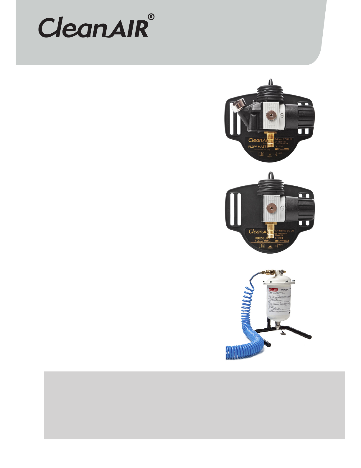
CleanAIR® Pressure Flow Master
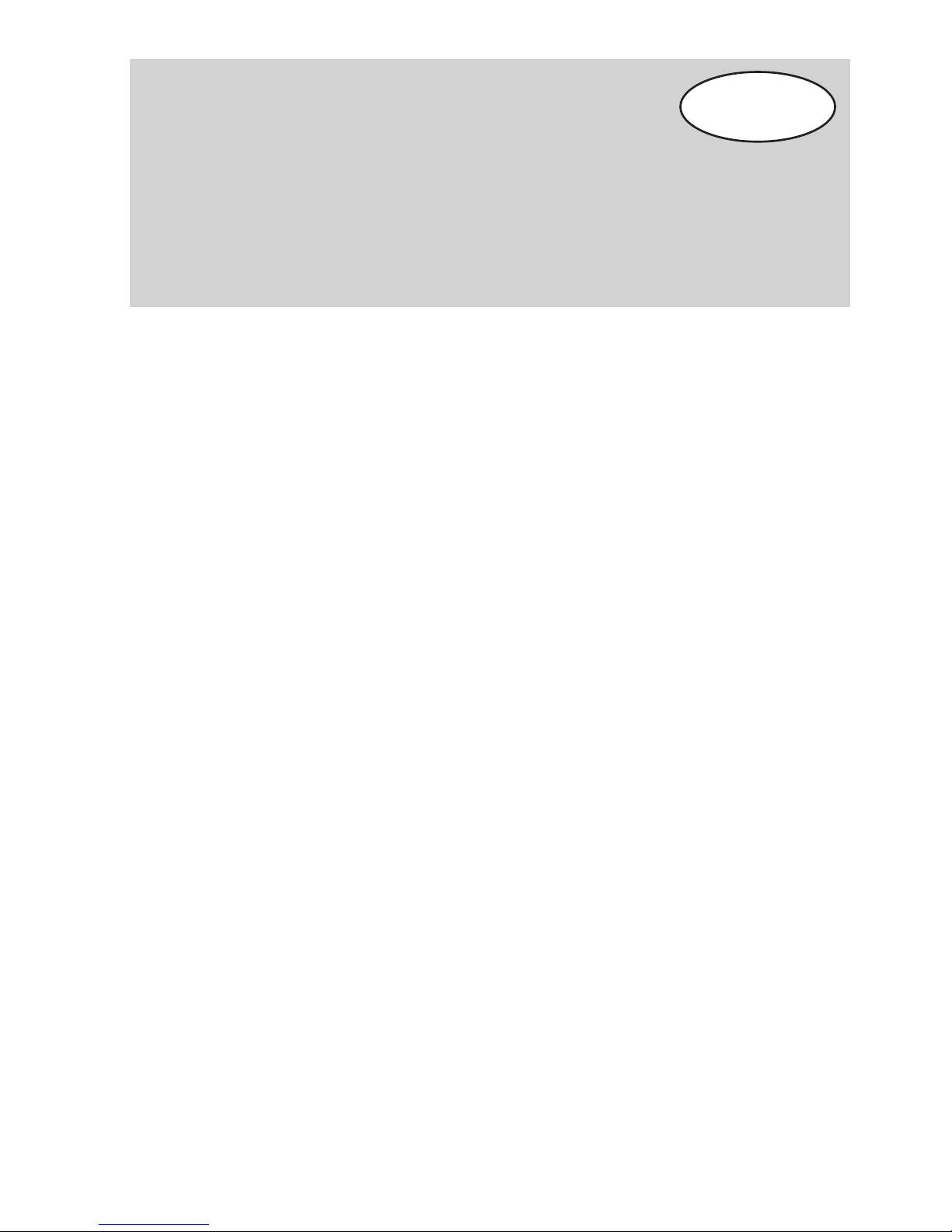
CleanAIR® Pressure
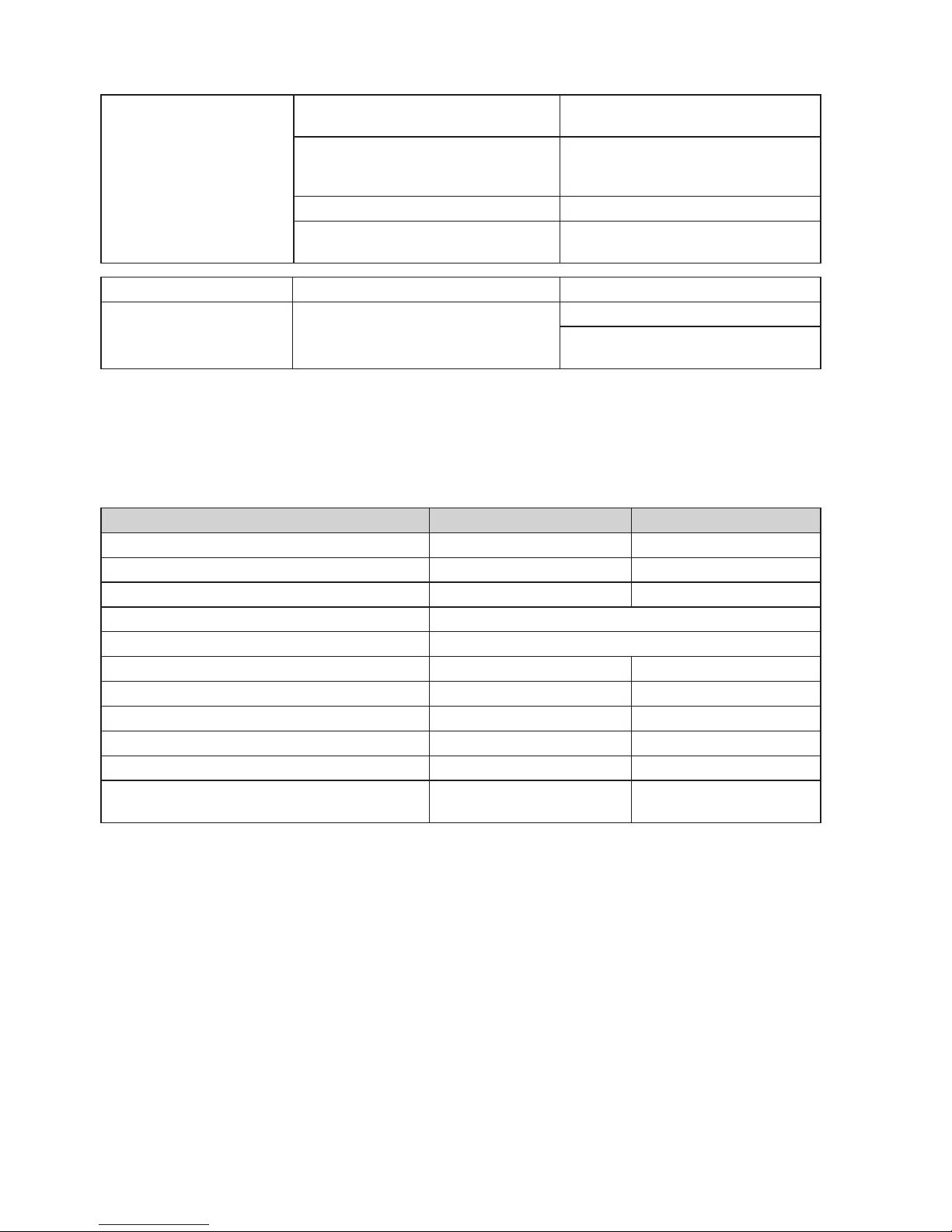
CleanAIR® Pressure Conditioner
NA-013-R03
GER X
NOR X
RUS X
SPA X
SWE X
ENG 3
CZE X
DUT X
FIN X
FRE X
PERSONAL RESPIRATORY PROTECTION SYSTEMS
USER MANUAL

3
1. Introduction
CleanAIR® Pressure systems are systems of
continuous flow compressed air line breathing
apparatus. The system is based on the principle of
overpressure of filtered air in the breathing zone.
The air is taken from the source of compressed air
(compressor) delivered to CA Pressure Condi-
tioner where the solid particles, oil mists and
unpleasant odours are removed. Then is the air delive-
red to CA Pressure/CA Pressure Flow Master, which
allows to regulate the airflow delivered through the
hose into a protective mask or hood. The overpressure
in the breathing zone prevents from entering of con-
taminants. This mild overpressure at the same time
ensures the wearer’s comfort, even with long-term
use, as the wearer does not have to struggle in their
breathing to overcome the resistance of the filter.
The air supplied from the compressor directly
(without use of CAP Conditioner filter) to CA Pressu-
re (Flow Master) must be hygienically clean and must
comply with the EN 12021 standard. If the air does not
comply with this requirement, install the CA Pressure
Conditioner filtration unit before the CA Pressure unit/
CAP Flow Master!
Apart from CA Pressure (CAP), CleanAIR® Pressure
Flow Master (CAP FM) is equipped with a pressure
gauge for the current check of the input pressure and
with warning whistle, which will warn the user in the
case of an inlet pressure decreases below the bottom
limit of operation pressure.
The air at the outlet of CA Pressure Conditioner
complies with EN 12021 if it is used within the range
of temperatures stated in Chapter 10 and the air from
the compressor complies with the requirements of
Chapter 1.1. CA Pressure Conditioner removes oil mist,
smells and flavours. There can be two users connec-
ted to the filtration station (CAP Conditioner).
CAP Conditioner does not remove carbon monoxide
(CO) and carbon dioxide (CO2) from the air!!!
1.1. Requirements for compressed air supplied
from the compressor
• CA Pressure Conditioner can only be connected to
compressor which supplies air at an oxygen con-
centration of 20 % to 22 % vol. The carbon dioxide
concentration must not exceed 500 ppm and the
carbon monoxide concentration must not exceed
15 ppm.
• The maximum concentration of water in the air
may be 50 mg/m³ at the rated pressure of 1 to
20 MPa. The humidity of the supplied air must be
controlled to prevent the unit from freezing.
2. Instructions for Use
Read this manual carefully and follow its instructions!!!
• The user must fully understand the instructions.
• During an extreme work load, the pressure in the
hood may reach negative values and the user may
feel air deficiency. In such case the protection of
air passages is reduced.
• The use of oxygen-enriched air and oxygen is
forbidden in the CleanAIR® system due to the risk
of explosion.
• The system may only be used in environ-
ments with a small probability of damage of the
supply hose and where the user’s movement is not
limited.
• If, apart from CleanAIR®, another accessory (e.g.
a spray gun) is connected to the compressed air
supply, the user must make sure that a sufficient
air flow to the hood is secured even at the maxi-
mum air consumption by this accessory.
• If the unit is used in environments with high tem-
peratures, the supply hose must be resistant to
such effects.
• It is forbidden to use the unit in explosive
enviroments.
• Before every use of the unit, check that the air
flow is higher than the minimum value specified in
the technical parameters.
• If the unit stops supplying air for any reason, the
user must leave the contaminated area immedia-
tely.
• The unit, in a combination with a welding helmet
Contents:
1. Introduction
2. Instructions for Use
3. Unpacking / Assembly / Use and Functions
4. Before Use
5. Maintenance / Cleaning
6. Spare Parts and their Replacement
7. Storage
8. Warranty
9. Possible faults
10. Technical Data
11. List of Parts
EN

4
or a safety helmet, is not recommended for users
with beard or long hair extending to the respiratory
zone.
• Beware of a higher CO2concentration in the air-
supply, which may occur if the compressor does
not work properly, when the lubricating oil someti-
mes burns due to high temperatures.
• The supply air pressure must be within the range
between 400 - 1000 kPa.
• The supply pressure hoses may only be located in
such places of the workplace where they cannot
be damaged.
• Pressure hoses for CA Pressure (Flow Master) and
CAP Conditioner, order No. 61 00 30 and 61 00 46,
are not antistatic and the maximum temperature to
which they are resistant without damage is 70 °C.
• The maximum length of the hose from the
compressed air distribution or CAP Conditioner to
the unit must not exceed 10 m.
• The recommended temperature range of use is
10 - 40 °C; at lower temperatures, the use of the
protective hood or mask with air supply may be
unpleasant.
• Before connecting the unit to the air distribution, it
is necessary to check what medium is in the line
and what is its quality.
• For the CA Pressure (Flow Master) it is necessary
to provide breathable air according to EN 12021.
• The CA Pressure units can be combined with the
types of head parts shown in the pictorial annex.
It shows also classes for the respective combina-
tions.
• Information on head parts are provided in the in-
structions for use of the CA head parts.
If any principles stated in this manual are breached,
the warranty becomes null and void!
3. Unpacking / Assembly /
Use and Functions
3.1. Unpacking CA Pressure
Check that the delivery is complete and no damage
occurred during transport.
Content of the CA Pressure (63 00 00), CA Pressu-
re Flow Master (67 00 00) contain:
CleanAIR® Pressure (Flow Master) unit 1 pc
Belt for the unit 1 pc
Air flow indicator 1 pc
User manual 1 pc
Content of the CA Pressure Conditioner (61 00 50):
CA Pressure Conditioner unit 1 pc
Unit stand 1 pc
Screws for connecting the unit to the stand 2 pcs
Gasket 4 pcs
Instruction for Use 1 pc
3.2. Assembly
CA Pressure (Flow Master) + CAP Conditioner
• Check that all components are in good condition,
i.e. without apparent damage.
• Connect CAP Conditioner to the compressed air
distribution system or straight to a compressor.
The air source must be equipped with a safety
valve (if CA Pressure Conditioner is not used, the
compressed air supply is connected straight to CA
Pressure (Flow Master).
• It is recommended using only original hoses supp-
lied by the manufacturer certified according to the
applicable standard.
• Check that the air pressure in the distribution sys-
tem corresponds to the range 300 to 1000 kPa.
• Attach the unit onto your belt and fit the connecti-
ng hose to it.
• Using the quick coupling, connect the pressure
hose from the compressed air source to the CA
Pressure unit. The hose from CAP Conditioner to
CA Pressure must not be longer than 10 metres.
• Check the air flow according to Chapter 4.2. The
lowest allowable flow rate is 170 l/min.
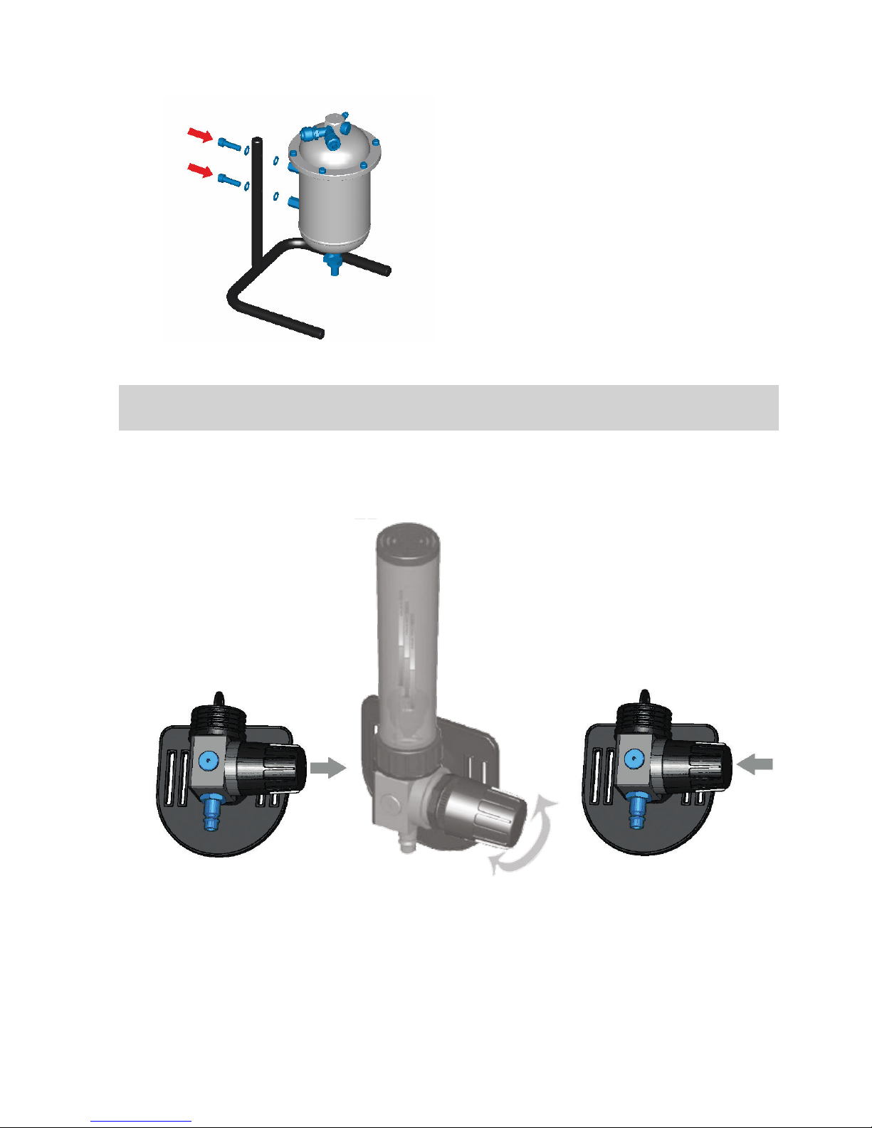
3.3. Assembling CAP Conditioner (61 00 50)
Screw the pressure vessel body onto the stand; for
the procedure see pictorial annex 1A.

5
4. Before Use
4.1. Check before use
Check before every use:
• that individual parts, particularly the air hose and
sealing elements, are not apparently damaged,
• that the hose is fitted correctly to the unit and to
the head part connector,
• that the air pressure in the distribution system
is in the range 300 to 1000 kPa (for both CA
Pressure and CAP Conditioner),
• that the air flow in the hose is sufficient (using
the air flow indicator, see Chapter 4.2.),
• that air is supplied from the head part.
4.2. Air flow test (CA Pressure / CA Flow Master)
All units are pre-adjusted on the airflow of 170 liters/
min. When measuring the airflow, follow the instruc-
tions in the manual enclosed to the flow indicator. If
the flow rate is different, proceed as follows:
1. Pull the reducing valve, you will hear a click. see.
pictorial annex 2A.
2. To set the optimal airflow, rotate the reducing val-
ve clockwise or counter-clockwise (to check the
airflow, you may conect flow meter) see. pictorial
annex 2B.
3. Push the reducing valve, you will hear a click (see.
pictorial annex 2C).
WARNING:
The airflow should not drop below 160 liters/min!
5. Maintenance and Cleaning
CA Pressure (Flow Master)
Every time you finish work, it is recommended to cle-
an the CA Pressure unit, to check individual parts and
to replace the damaged ones.
• Cleaning must be carried out in a well ventilated
room. Avoid inhaling the harmful dust settled on
individual parts of the unit and accessories!
• It is forbidden to use cleaning agents containing
solvents or abrasives. Detergents are recommen-
ded.
• The air hose can be rinsed with clean water.
• Use a damp cloth for cleaning. Each part must be
wiped dry after cleaning.
CA Pressure Conditioner
• Once a week, drain the condensate from the con-
tainer bottom by the cock located on the bottom
side. Before this operation, it is recommended
disconnecting the unit from the compressed air
supply.
• Replace the filter at least once in three months.
After this period, viruses and bacteria may proli-
ferate in the unit filter and if it is used regularly,
the absorption capacity of the activated carbon
eliminating smells may be exhausted (if the air lea-
ving CA Pressure Conditioner smells in any way,
replace the filter immediately).
• When replacing the filter, clean the inner part of
the container with a dry cloth or detergent.
6. Spare Parts and their
Replacement
6.1. Filter for CA Pressure Conditioner
The filter plant CAP Conditioner contains a combined
filter which removes oil mist, smells and flavours from
industrially produced compressed air.
The filter does not remove CO and CO2!
Read the instructions for use and replacement.
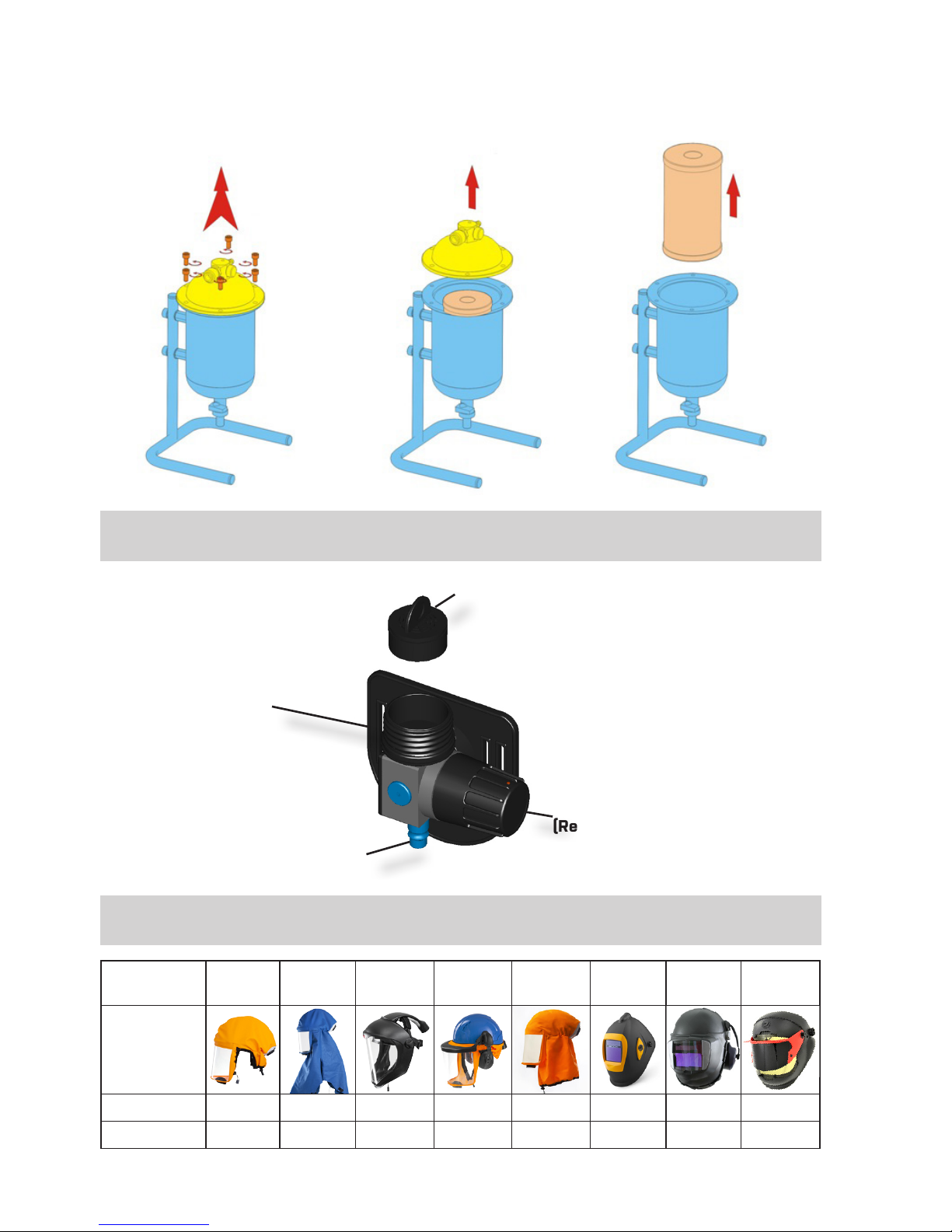
Replacing CA Pressure Conditioner filter:
See pictorial annex 3A-3C
• Unscrew the top part of the filter pressure contai-
ner (6 screws).
• Remove the contaminated filter, wipe the inside of
the container.
• Check the condition of the rubber seal in the top
cover. If the seal is damaged, replace it.
• Install a new filter, put the container cover on and
screw it back.
• Check the container for leakage. If the container is
not absolutely tight, tighten all screws that fasten
the top cover.
7. Storage
If any fault, sudden decrease or increase in air supply
occurs and the user is at a contaminated workplace,
it is necessary to leave the workplace and to check
the following:
• That the unit is assembled correctly.
• The filter condition in CA Pressure Conditioner.
• That the air hose is not damaged. It is necessary
to make sure that, during work, the hose is not got
caught at projecting objects and a crack cannot
occur.
• That the noise damper in CA Pressure is not
clogged.
• That the seal on the safety hood is in good con-
dition. All components of CleanAIR® systems must
be stored in rooms with temperatures between
0 °C and 40 °C with relative air humidity between
20 % and 80 %. The storage time in closed con-
tainers is max. 2 years, except for the batteries!.
8. Warranty
Warranty for manufacturing defects is 12 months from
the date of sale to the customer. A claim must be filed
with the sales organization and the proof of sale (in-
voice or delivery note) must be submitted.
Warranty does not cover in particular defects caused
by a late replacement of the filter or by using a filter
damaged by cleaning or blowing.
CA Pressure Pressure Pressure FM
Minimum air flow 170 lpm 170 lpm
Maximum air flow 400 lpm 250 lpm
Weight of unit 250 g 280 g
Inlet connection Compatible with RECTUS series 25, 26 and CEYN320
Outlet connection CA40x1/7“
Noise level of unit 61 dB 61 dB
Waist size 60 – 150 cm 60 – 150 cm
Supply pressure range 300 – 1000 kPa 400 – 1000 kPa
Recommended temperature range at work +10 to +60 °C +10 to +60 °C
Recommended air humidity range at workplace 20 % to 80 % Rh 20 % to 80 % Rh
Certification EN 14594 Class 2A EN 14594 Class 2A, 2B,
3A, 3B
10. Technical Data
Notified body for CE testing: Výzkumný ústav bezpečnosti práce, v.v.i. – ZL
Testing Laboratory No. 1024, Jeruzalémská 9, 116 52 Praha 1
Authorized Body 235 | Notified Body 1024
6
The unit does not supply
the sufficient amount of air.
Air hose or air channel blocked. Check and remove the possible ob-
stacle.
Air escapes through leakages.
Check all sealing elements and co-
nnections, check that the hose is not
damaged and without leaks.
The baffle is clogged. Replace the baffle in CA Pressure .
The filter in CA Conditioner is clogged. Replace the filter.
Fault Probable cause Recommendation
The unit does not work at
all.
Compressed air supply failure. Hose
damage.
Check the compressed air source.
Check that connecting hoses are not
damaged.
9. Possible Faults

CleanAIR® Pressure Conditioner
Maximum air flow 500 l/min
Weight without filter 6 300 g
Weight including filter 6 800 g
Inlet connection Compatible with RECTUS series 25,26 a CEYN320
Outlet connection Compatible with RECTUS series 25,26 a CEYN320
Recommended temperature range at work +10 to +60 °C
Recommended air humidity range at workplace 20 % to 80 % Rh
Certification If the requirements of TP-610050-1 are met, it com-
plies with EN 12021
11. List of Spare Parts:
CleanAIR® Pressure / CA Pressure Flow Master
Order No.: Description:
63 00 00 CA Pressure + belt
67 00 00 CA Pressure Flow Master + comfort belt
61 00 30 Standard hose 10 m for CAP
61 00 38 Standard hose 25 m for CAP
61 00 39 Standard hose 50 m for CAP
61 00 46 Spiral hose 10 m for CAP, mechanically resistant - mod.
63 00 10 CA Pressure - silencer
70 00 60 Light flexi hose CA40x1/7“ - CA40x1/7“
70 00 86CA Rubber hose CA40x1/7“ - CA40x1/7“
70 00 95 Belt for CA Pressure 155 cm
70 00 90RD Air flow indicator
CA PRESSURE CONDITIONER
Order No.: Description:
61 00 50 CleanAIR® Pressure Conditioner
61 00 10 Filter for CleanAIR® Pressure Conditioner
61 00 24 CleanAIR® Pressure Conditioner - sealing O-ring 139x3
61 00 28 CleanAIR® Pressure Conditioner - sealing O-ring 30x4
7

8
1. Úvod
CleanAIR® Pressure je systém umožňující kontinuální
zásobování dýchatelným vzduchem ze zdroje stlače-
ného vzduchu. Systém je založen na principu přetlaku
filtrovaného vzduchu v dýchací zóně. Vzduch je při-
jímán ze zdroje stlačeného vzduchu (kompresoru, či
tlakové láhve), přepraven do CA Pressure Conditioner
kde jsou následně odstraněny pevné částice, olejové
mlhy a nepříjemné pachy. Následně je vzduch přepra-
ven do CA Pressure / CA Pressure Flow Master, kte-
rý umožňuje regulovat množství vzduchu přicházející
hadicí do ochranné masky, či kukly. Přetlak v dýcha-
cí zóně zabraňuje vstupu kontaminantů. Tento mírný
přetlak ve stejné chvíli zajišťuje komfort uživatele i při
dlouhodobém používání, protože uživatel nemusí při
dýchání překonávat odpor filtru.
Vzduch přiváděný z kompresoru (bez použití CAP Con-
ditioner filtru) přímo do CA Pressure (Flow Master)
musí být hygienicky čistý a musí vyhovovat normě
EN 12021. Pokud vzduch nevyhovuje těmto podmín-
kám, je nutné zařadit CA Conditioner mezi zdroj tlako-
vého vzduchu a CA Pressure (Flow Master).
CA Pressure (Flow Master) je taktéž vybaven tlako-
měrem pro kontrolu vstupního tlaku a současně i bez-
pečnostní píšťalkou, která varuje uživatele v případě,
že vstupní tlak poklesne pod spodní limit povoleného
provozního tlaku.
Vzduch na výstupu z CA Pressure Conditioner vyho-
vuje normě EN 12021 v případě je používán v rozsahu
teplot uvedených v kapitole 10 a vzduch z kompre-
soru vyhovuje požadavkům uvedeným v kapitole 1.1.
CA Conditioner odstraňuje olejové mlhy, pachy a chutě.
V jeden okamžik mohou být k filtrační stanici připojeni
dva uživatelé (CA Pressure Conditioner).
CAP Conditioner neodstraňuje ze vzduchu oxid uhel-
natý (CO) and oxid uhličitý (CO2)!!!
1.1. Požadavky na stlačený vzduch přicházející z
kompresoru
• CA Pressure Conditioner může být připojen pouze
na kompresor distribuující vzduch s procentuelním
zastoupením vzduchu 20 % až 22 %. Koncentrace
oxidu uhličitého nesmí překročit 500 ppm a kon-
centrace oxidu dusného nesmí překročit 15 ppm.
• Koncentrace vody ve vzduchu by neměla překročit
50 mg/m³ při jmenovitém tlaku vzduchu v rozmezí
1 - 20 MPa. Vlhkost vzduchu přicházejícího z kom-
presoru musí být kontrolována jako prevence proti
zamrznutí jednotky.
2. Návod k použití
Čtěte tento návod pozorně a postupujte dle pokynů!!!
• Uživatel musí nejprve plně chápat pokyny.
• V případě extrémní pracovní zátěže může tlak v
kukle, či masce klesnout pod úroveň atmosferic-
kého tlaku a uživatel může pociťovat nedostatek
vzduchu. V těchto případech může být ochrana
uživatele snížena.
• Při použití systému CleanAIR® je kvůli hrozbě explo-
ze zakázáno používat vzduch obohacený o kyslík.
• Systém může být použit pouze v prostředí s níz-
kou pravděpodobností poškození přívodní hadice,
prostředí v němž je systém využíván by zároveň
nemělo uživatele omezovat v pohybu.
• V případě, že je kromě systému CleanAIR® k pří-
vodu stlačeného vzduchu připojeno další příslu-
šenství (např. vzduchová pistole), uživatel se musí
ujistit, že je zajištěn dostatečný přívod vzduchu do
hlavového dílu i při maximálním využití připojeného
příslušenství.
• Pokud je zařízení používáno v prostředích s vyso-
kými teplotami, přívodní hadice musí být vůči tomu-
to vlivu odolná.
• Je zakázáno používat zařízení ve výbušném pro-
středí.
• Před každým použitím zkontrolujte, že je skutečný
průtok vzduchu vyšší, nežli minimální hodnot uve-
dená ve technických parametrech.
Obsah:
1. Úvod
2. Návod k použití
3. Rozbalení / montáž / funkce a použití
4. Před prvním použitím
5. Údržba a čištění
6. Výměna náhradních dílů
7. Skladování
8. Záruka
9. Jak postupovat v případě selhání
10. Technické údaje
11. Seznam dílů
CZ

9
• Pokud z jakéhokoli důvodu jednotka přestane do-
dávat vzduch, uživatel musí neprodleně opustit
kontaminovanou oblast.
• Jednotka v kombinaci se svářecí kuklou, nebo bez-
pečnostní přilbou není doporučená pro uživetele s
bradkou, nebo s dlouhými vlasy přesahujícími do
dýchací zóny.
• Dejte si pozor na zvýšené koncentrace CO2 na
vstupní straně, které se mohou vyskytnout v pří-
padě, že kompresor nepracuje správně (v případě,
že mazací olej spalován díky vysokým teplotám).
• Vstupní tlak musí být v mezích 400 - 1000 kPa.
• Hadice přivádějící tlakový vzduch mohou být umís-
těny pouze na místech, kde nemohou být poško-
zeny.
• Tlakové hadice pro CA Pressure (Flow Master)
a CAP Conditioner, objednací číslo 61 00 30 a
61 00 46 nejsou antistatické a maximální teploty
vůči kterým jsou odolné bez poškození činí 70 °C.
• Maximální vzdálenost tlakové hadice vedoucí z
kompresoru, nebo z CAP Conditioner činí 10 m.
• Doporučený rozsah teplot pro použití je 10 - 40 °C;
při nižších teplotách může být používání ochranné
kukly, či masky nepohodlné.
• Před napojením jednotky k centrálnímu rozvodu
vzduchu je nutné zkontrolovat jaký plyn se nachází
v rozvodu a jaké je kvality.
• Jednotku CA Pressure (Flow Master) je nezbyt-
né zásobovat dýchatelným vzduchem dle normy
EN 12021.
• Jednotky CA Pressure (Flow Master) mohou být
kombinovány s hlavovými díly uvedenými v obrázo-
vé příloze. Můžete zde nalézt taktéž ochranné třídy
pro dané kombinace.
• Návod k použití hlavových dílů je vždy přiložen ke
konkrétnímu produktu.
Pokud je kterýkoli z uvedených principů v tomto
manuálu porušen záruka zaniká!
3. Rozbalení / montáž / funkce a použití
3.1. Rozbalení CA Pressure
Zkontrolujte, že dodávka je kompletní a nedošlo k
žádnému poškození při přepravě.
Obsah balení CA Pressure (63 00 00) a CA Pressure
Flow Master (67 00 00) obsahuje:
Jednotka CleanAIR® Pressure (Flow Master) 1 ks
Opasek 1 ks
Indikátor průtoku vzduchu 1 ks
Návod 1 ks
Obsah balení CA Pressure Conditioner (61 00 50):
Jednotka CA Pressure Conditioner 1 ks
Stojan 1 ks
Šrouby k upevnění na stojan 2 ks
Podložky 4 ks
Návod 1 ks
3.2. Sestavení
CA Pressure (Flow Master) + CAP Conditioner
• Zkontrolujte, že jsou všechny komponenty v pořád-
ku, tj. bez zjevného poškození.
• Připojte CA Pressure Conditioner k rozvodu stlače-
ného vzduchu, nebo přímo ke kompresoru. Zdroj
vzduchu musí být vybaven bezpečnostním venti-
lem. Pokud není CA Pressure Conditioner použit,
tlakový vzduch připojte přímo k CA Pressure (Flow
Master).
• Je doporučeno používat pouze originální hadice
dodávané výrobcem certifikované dle dané normy.
• Zkontrolujte, že tlak vzduchu v distribučním systé-
mu odpovídá rozsahu 300 - 1000 kPa.
• Upevněte jednotku na opasek a propojte pomocí
vzduchové hadice do hlavového dílu.
• Pomocí rychlospojky připojte tlakovou hadici ze
zdroje tlakového vzduchu k jednotce CA Pressure
(Flow Master). Hadice z CA Pressure Conditioner
nesmí být delší, než 10 metrů.
• Zkontrolujte skutečný průtok vzduchu indikátorem
průtoku vzduchu dle kapitoly 4.2. Nejnižsí povolený
průtok vzduchu je 170 l/min.
3.3. Sestavení CA Pressure Conditioner (61 00 50)
Sešroubujte jednotku CA Pressure Conditioner se
stojanem. Jako návod použijte obrazovou přílohu 1A.

10
4. Před prvním použitím
4.1. Zkontrolujte před použitím
Před každým použitím zkontrolujte:
• že nejsou jednotlivé díly (vzduchová hadice a
těsnění) poškozeny,
• že je vzduchová hadice správně připojena k
jednotce i k hlavovému dílu,
• že je tlak v rozvodu zlakového vzduchu v roz-
mezí 300 až 1000 kPa (pro CA Pressure (Flow
Master) i CA Pressure Conditioner),
• že je průtok vzduchu na výstupu z jednotky
dostatečný (dle indikátoru průtoku vzduchu, viz
kapitola 4.2),
• že je hlavový díl zásobován vzduchem.
4.2. Test průtoku vzduchu CA Pressure (Flow Master)
Jednotky jsou přednastaveny na průtok vzduchu
170 l/min. V případě, že měříte průtok vzduchu, dbej-
te pokynů v návodu přiloženému k indikátoru průtoku
vzduchu. Pokud naměřený průtok neodpovídá, učinte
následující kroky:
1. Uvolněte tahem redukční ventil (uslyšíte cvaknutí).
Viz. obrazová příloha 2A.
2. Pro nastavení optimálního průtoku vzduchu otá-
čejte redukčním ventilem po směru, či proti směru
hodinových ručiček. Pro kontrolu průtoku vzduchu
připojte indikátor průtoku vzduchu (viz. obrazová
příloha 2B).
3. Zatlačte na redukční ventil a vraťte ho do původ-
ní pozice - uslyšíte cvaknutí (viz. obrazová příloha
2C)
VAROVÁNÍ:
Průtok vzduchu by neměl klesnout pod 160 l/min!!!
5. Údržba a čištění
CA Pressure (Flow Master)
Na konci každé směny je doporučené vyčistit
jednotku, zkontrolovat jednotlivé díly a vyměnit poško-
zené části.
• Čištění jednotky musí probíhat v dobře ventilované
místnosti. Vyhněte se vdechnutí škodlivého pra-
chu usazeného na jednotlivých částech jednotky
a příslušenství!
• Je zakázáno používat čistící prostředky obsahující
rozpouštědla a abrazivní látky. K čištění lze dopo-
ručit běžné detergenty.
• Vzduchová hadice může být opláchována čistou
vodou.
• K čištění používejte vlhký hadr. Každá část musí
být utřena do sucha.
CA Pressure Conditioner
• Jednou za týden vypusťte zkondenzovanou vodu
vodu z nádrže za pomoci výpusti umístěné na
spodní části. Před tímto úkonem je doporučeno
odpojit jednotku od zdroje stlačeného vzduchu.
• Vyměňte tento filtr vždy alespoň jednou za
3 měsíce. Po uplynutí této doby se mohou v
jednotce začít velmi rychle množit viry a bakterie.
V případě, že je jednotka používána pravidelně,
absorbční kapacita aktivního uhlí eliminujícícho zá-
pach může být vyčerpána (pokud vzduch vychá-
zející z jednotky CA Pressure Conditioner jakkoli
zapáchá, vyměňte okamžitě filtr).
• Když měníte filtr, vyčistěte nejprve vnitřek jed-
notky suchým hadrem, nebo za pomoci běžného
detergentu.
6. Výměna náhradních dílů
6.1. Filter pro CA Pressure Conditioner
Zařízení CA Pressure Conditioner obsahuje
kombinovaný filtr odstraňující olejové mlhy, zápachy a
chutě z průmyslově vyráběného stlačeného vzduchu.
Filtr neodstraňuje CO and CO2!
Čtěte instrukce k použití a výměně.
Výměna filtru CA Pressure Conditioner:
viz. obrázková příloha 3A-3C
• Odšroubujte horní část jednotky (6 šroubů).
• Odstraňte filtr jednotky a vyčistěte její vnitřek.
• Zkontrolujte stav pryžového těsnění víka jednotky.
Pokud je poškozené, vyměňte ho.
• Vložte nový filtr, nasadtě víko filtru a našroubujte
ho zpátky.
• Zkontrolujte zdali z nádoby neuniká vzduch.
Pokud není nádoba naprosto těsná, utáhněte zno-
vu všechny šrouby na horní straně.
7. Skladování
Všechny komponenty systému CleanAIR® musí být
skladovány v prostorách s teplotami v rozsahu 0 °C
až 40 °C s relativní vlhkostí 20 % až 80 %. Možná doba
skladování v uzavřených kontejnerech je maximálně
2 roky s výjimkou baterií.
8. Záruka
Záruka pro výrobní závady je 12 měsíců od data
prodeje koncovému zákazníkovi. Nárok musí být
uplatněn u prodávajícího při současném předložení
faktury, či dodejky.
Záruka ztrácí platnost v případě poškození
způsobeného pozdní výměnou filtru, nebo použitím
filtru poškozeného čištěním, nebo profukováním.
CA Pressure Pressure Pressure Flow Master
Minimální průtok 170 l/min 170 l/min
Maximální průtok 400 l/min 250 l/min
Hmotnost jednotky 250 g 280 g
Vstupní konektor Compatible with RECTUS series 25, 26 and CEYN320
Výstupní konektor CA40x1/7“
Hlučnost jednotky 61 dB 61 dB
Délka opasku 60 - 150 cm 60 - 150 cm
Rozsah možného vstupního tlaku 300 – 1000 kPa 400 – 1000 kPa
Doporučený teplotní rozsah při práci +10 to +60 °C +10 to +60 °C
Doporučená relativní vzdušná vlhkost při práci 20 % to 80 % 20 % to 80 %
Certifikace EN 14594 Class 2A EN 14594 Class 2A, 2B,
3A, 3B
10. Technické údaje
Notifikovaná osoba pro testování CE: Výzkumný ústav bezpečnosti práce, v.v.i. – ZL
Testovací laboratoř č. 1024, Jeruzalémská 9, 116 52 Praha 1
Autorizovaná osoba 235 | Notifikovaná osoba 1024
11
Jednotka neposkytuje
dostatečné množství
vzduchu.
Hadice, nebo vzduchový kanál jsou ucpané. Zkontrolujte a odstraňte případné
překážky.
Vzduch uniká díky netěsnostem.
Zkontrolujte všechny těsnící elementy
a spoje a prověřte zdali není hadice
poškozená a neobsahuje díry.
Tlumič hluku je ucpaný. Vyměňte tlumič hluku.
Filtr v CA Pressure Conditioner je ucpaný. Vyměňte filtr.
Závada Pravděpodobná příčina Doporučení
Jednotka vůbec nefunguje Závada na straně zdroje tlakového
vzduchu, nebo poškozená hadice.
Zkontrolujte zdroj stlačeného vzduchu.
Ověřte, zdali jsou propojovací hadice
v pořádku.
9. Jak postupovat v případě selhání

CleanAIR® Pressure Conditioner
Maximální průtok vzduchu 500 l/min
Hmotnost bez filtru 6 300 g
Hmotnost včetně filtru 6 800 g
Vstupní konektor Compatible with RECTUS series 25,26 a CEYN320
Výstupní konektor Compatible with RECTUS series 25,26 a CEYN320
Doporučený teplotní rozsah při práci +10 to +60 °C
Doporučená relativní vzdušná vlhkost při práci 20 % to 80 % Rh
Certifikace Pokud jsou splněny požadavky uvedené v
TP-610050-1, pak odpovídá EN 12021
11. Seznam náhradních dílů:
CleanAIR® Pressure a CleanAIR® Pressure Flow Master
Objednací č.: Popis:
63 00 00 CA Pressure + belt
67 00 00 CA Pressure Flow Master + comfort belt
61 00 30 Standard hose 10 m for CAP
61 00 38 Standard hose 25 m for CAP
61 00 39 Standard hose 50 m for CAP
61 00 46 Spiral hose 10 m for CAP, mechanically resistant - mod.
63 00 10 CA Pressure - silencer
70 00 60 Light flexi hose CA40x1/7“ - CA40x1/7“
70 00 86CA Rubber hose CA40x1/7“ - CA40x1/7“
70 00 95 Belt for CA Pressure 155 cm
70 00 90RD Air flow indicator
CA PRESSURE CONDITIONER
Objednací č.: Popis:
61 00 50 CleanAIR® Pressure Conditioner
61 00 10 Filtr pro CleanAIR® Pressure Conditioner
61 00 24 CleanAIR® Pressure Conditioner - sealing O-ring 139x3
61 00 28 CleanAIR® Pressure Conditioner - sealing O-ring 30x4
12
13
CA Pressure conditioner assembly
1A
Airflow adjustment
CA Pressure, CA FM
2A 2B 2C
14
Filter change
3A 3B 3C
CA Pressure, CA FM
Exchangable silencer
Airflow regulation
(Reducing Valve)
Pressure hose connector
Headtop CA-1 CA-2 CA-3 CA-4 CA-10 CA-20 CA-40
/G/GW
CA-28
Euromaski
Unit
CA Pressure 2A 2A 2A 2A x x 2A 2A
CA FM 2A 2A 2A 3A 2A 3B 2B 2A
Possible combinations
Hose connector

15

16
MALINA - Safety s.r.o.
Luční 11,
466 01 Jablonec n. Nisou
Czech Republic
Tel. +420 483 356 600
Fax +420 483 312 106
export@malina-safety.cz
www.malina-safety.com
This manual suits for next models
2
Table of contents
Languages:
Popular Diving Instrument manuals by other brands


Ocean Reef
Ocean Reef Extender Kit instruction manual

Aqua Lung
Aqua Lung i300C owner's manual

Sherwood Scuba
Sherwood Scuba Insight Manual guide

Northern Diver
Northern Diver SRE SQUEEZE LOCK KNIFE user manual

Ocean Reef
Ocean Reef AQUARIST owner's manual

Blueprint Subsea
Blueprint Subsea ArtemisPRO Technical manual


