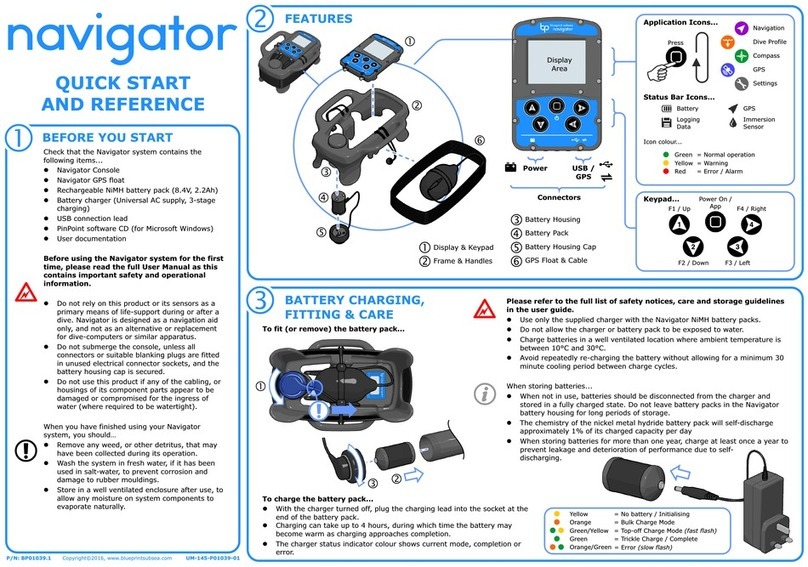
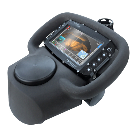
Blueprint Subsea ArtemisPRO User manual

ArtemisPRO
Technical Manual


ArtemisPRO
Technical Manual
6-3
Contents
1. Documentation .........................................................................................................................................................5
2. Notices.......................................................................................................................................................................6
3. Introduction ..............................................................................................................................................................7
4. Parts List....................................................................................................................................................................8
5. Maintenance & Storage...........................................................................................................................................10
5.1. Pre-Dive Preparation .......................................................................................................................................10
5.2. Post-Dive Maintenance & Short Term Storage ...............................................................................................10
5.3. Long Term Storage ..........................................................................................................................................11
5.4. Connector Lubrication ....................................................................................................................................11
6. Troubleshooting .....................................................................................................................................................12
7. Settings Manager ....................................................................................................................................................15
7.1. System Menu ...................................................................................................................................................16
7.2. Set Clock Menu ................................................................................................................................................16
7.3. Sensor Menu ....................................................................................................................................................17
7.4. Display Menu....................................................................................................................................................17
7.5. Sonar Menu......................................................................................................................................................18
7.6. Navigation Menu..............................................................................................................................................18
8. Updating Console Software....................................................................................................................................19
9. Battery Pod and Battery Charger ...........................................................................................................................20
9.1. Battery Performance .......................................................................................................................................20
9.1.1. Self-Discharge.................................................................................................................................................................................... 20
9.1.2. Memory Effect.................................................................................................................................................................................... 20
9.1.3. Storage............................................................................................................................................................................................... 20
9.1.4. Reconditioning .................................................................................................................................................................................. 20
9.2. Battery Handling..............................................................................................................................................21
9.2.1. Safety Precautions............................................................................................................................................................................. 21
9.2.2. Disposal or recycling.......................................................................................................................................................................... 21
9.2.3. Transport Regulations....................................................................................................................................................................... 21
9.3. Battery Charger................................................................................................................................................22
9.3.1. Safety Precautions............................................................................................................................................................................. 22
9.3.2. Charger Fuse...................................................................................................................................................................................... 22
9.3.3. Charge Sequence Diagram ................................................................................................................................................................ 22
9.3.4. Charging Duration ............................................................................................................................................................................. 23
9.3.5. Charging Errors.................................................................................................................................................................................. 23
9.3.6. Interrupting a Charge ........................................................................................................................................................................ 23
9.3.7. Charging Complete............................................................................................................................................................................ 23
10. Electrical Wiring ....................................................................................................................................................24
10.1. System Connections......................................................................................................................................24
10.2. Console Connectors ......................................................................................................................................25
10.2.1. Console USB (User) Connector........................................................................................................................................................ 25
10.2.2. Console Battery Pod (NiMH) Connector.......................................................................................................................................... 26
10.2.3. Console Navigation Pod Connector ................................................................................................................................................ 26
10.2.4. Console Sonar Connector................................................................................................................................................................ 26
10.2.5. Console Aux Sensor Connector (Option)......................................................................................................................................... 27
10.2.6. Console Video Camera Connector (Option) .................................................................................................................................... 27
10.2.7. Console Dive-Light Connector (Option) .......................................................................................................................................... 27
10.3. Battery Pod (NiMH) Connector......................................................................................................................28
10.4. Navigation Pod Connector ............................................................................................................................29

ArtemisPRO
Technical Manual
6-4
10.5. Sonar (Oculus) Connector .............................................................................................................................29
11. Specifications........................................................................................................................................................30
11.1. System ...........................................................................................................................................................30
11.2. Console ..........................................................................................................................................................30
11.3. Multibeam Sonar ...........................................................................................................................................31
11.4. Navigation Pod ..............................................................................................................................................31
11.4.1. Doppler Velocity Log........................................................................................................................................................................ 31
11.4.2. GNSS Receiver (Integrated) ............................................................................................................................................................. 31
11.4.3. Attitude & Heading Sensor .............................................................................................................................................................. 32
11.4.4. Water Sensor.................................................................................................................................................................................... 32
11.5. Camera (optional)..........................................................................................................................................32
11.6. Dive-Light (optional)......................................................................................................................................32
11.7. Battery Pack (NiMH) ......................................................................................................................................33
11.8. Battery Charger..............................................................................................................................................33
11.9. Transit Case ...................................................................................................................................................33
12. Product Support ...................................................................................................................................................34
12.1. Website ..........................................................................................................................................................34
12.2. Technical Support .........................................................................................................................................34
13. Limited Warranty Policy .......................................................................................................................................35
14. Glossary.................................................................................................................................................................36

ArtemisPRO
Technical Manual
6-5
1. Documentation
For ease of reading and training the ArtemisPRO documentation is split into several sections:
1. Getting Started
Guide
Covers the basics to quickly allow a user to power up ArtemisPRO,
understand and use the interface, operate the sonar, prepare and dive a
mission file, review the collected Dive-Log data and put the system into
storage after use.
2. System Manual
Provides in-depth information for the operation and use of the main
ArtemisPRO hardware, including:
Charging and using the battery packs.
Powering up and turning off the system.
Understanding and using the various information displays.
Operational procedures for pre-dive and post-dive checks,
maintenance and storage.
3. Sonar Manual
Provides theory and operational information regarding the use of the
forward-looking multibeam sonar system, including:
Basic sonar theory and concepts
How to interpret sonar imagery and get the best results from the
sonar.
How to control the sonar (range, gain and frequency settings).
General procedure to help find targets and perform search
operations.
4. Navigation Manual
Provides information and instructions for using the navigation system
(containing DVL, GNSS receiver and AHRS sensors), including:
Theory of operation for each of the sensors,
How to use the navigation display
Creating mission files and defining markers and waypoints
Calibrating the compass
Swimming a mission
Replaying and reviewing Dive-Log data.
5. NavPoint Software
Manual
NavPoint is the ‘Windows’ software application that can be used to plan
mission files prior to a dive, or review Dive-Log data collected during a dive.
This document covers the installation and operation of the NavPoint
software application.
6. Technical Manual
(This document)
Contains information relating to the correct maintenance and storage of the
ArtemisPRO system as well as Troubleshooting and Technical Reference,
Specification and Support details.

ArtemisPRO
Technical Manual
6-6
2. Notices
Symbols
Throughout the ArtemisPRO documentation the following symbols are used to indicate special precautions or
procedures:
WARNING!
This symbol indicates a warning you should follow to avoid bodily injury or damage to your equipment.
CAUTION
This symbol denotes precautions and procedures you should follow to avoid damage to your equipment.
NOTE
This symbol denotes special instructions or tips that should help you get the best performance from your
ArtemisPRO system.
Copyright
Blueprint Subsea is a trading name of Blueprint Design Engineering Ltd.
Copyright © 2015 Blueprint Design Engineering Limited, all rights reserved.
No part of this publication may be reproduced, stored in a retrieval system, or transmitted in any form or by means
(electronic, mechanical, photocopying, recording or otherwise), without the prior written permission of Blueprint
Design Engineering Ltd.
Disclaimer
Neither Blueprint Design Engineering Limited, or their affiliates shall be liable to the purchaser of this product, or
third parties, for losses, costs, damages or expenses incurred by the purchaser or third parties as a result of
accident, misuse, abuse, modification of this product or a failure to strictly comply with the operating and
maintenance instructions.
Trademarks
The Windows™ operating system is a trademark of the Microsoft Corporation. The Google Earth™ mapping service
is a trademark of Google Inc. Other product and brand names used within this document are for identification
purposes only. Blueprint Design Engineering Ltd. disclaims any and all rights in those marks.
Third-Party Software Applications
Third-party applications referred to in this document (such as Google Earth and Microsoft Windows) are not
affiliated with Blueprint Design Engineering Ltd. in any way, and the content provided here is on an “as is” basis
for information only. Blueprint Design Engineering Ltd. can offer no technical support for these applications
(unless stated otherwise in the text), or accept responsibility whatsoever for any damages arising out of the use
of information contained in the documentation by other parties, and makes no guarantees, expressed or implied,
about its availability, quality, reliability, functionality or any other characteristic.
Specifications & Content
All information in this document is believed to be correct at the time of going to press, Blueprint Design
Engineering Ltd cannot be held responsible for any inaccuracies or omissions. If you find an error or feel we have
missed important or useful information, please contact us. The latest version of the manual is always available to
download from the website.
Specifications and information contained in this document are subject to change without notice, and does not
represent a commitment on the part of Blueprint Design Engineering Ltd.

ArtemisPRO
Technical Manual
6-7
Handling Recommendations
The ArtemisPRO system contains sensitive electronic components that may be damaged by an Electrostatic
Discharge (ESD) if handled incorrectly. To minimise risk of damage, users should avoid dismantling the unit,
touching any exposed electrical contacts on external connector, or inserting anything other than the
recommended cabling into the connectors.
Waste Electrical & Electronic Equipment Statement
Under the European Union (EU) directive on 'Waste Electrical & Electronic Equipment' (Directive 2002/96/EC),
from August 13, 2005, products categorised as electrical or electronic equipment cannot be discarded as
municipal waste by placing in landfill, dumping in the sea or incineration. SEPARATE collection is mandatory.
At the end of its life, you should either return this system and its associated leads & accessories (if appropriate) to
Blueprint Design Engineering Ltd with a certificate of decontamination (we reserve the right to protect our staff
from the effects of any contamination) or it should be sent to an appropriate treatment or recycling agency.
Restriction of Hazardous Substances Statement
Under the European Union (EU) directive on the 'Restriction of Hazardous Substances' (Directive 2002/95/EC),
from July 1, 2006, electrical and electronic equipment cannot contain lead ("lead free"), mercury, cadmium,
hexavalent chromium, polybrominated biphenyls (PBB) or polybrominated diphenyl ethers (PBDE).
All components of the ArtemisPRO system, sold by Blueprint Design Engineering Ltd, fully comply with this
legislation where applicable.
3. Introduction
ArtemisPRO is a self-contained diver target detection sonar and underwater navigation aid. The system combines
a forward looking multi-beam imaging sonar, Doppler-Velocity-Log (DVL) sensor, Global Navigation Satellite
System (GNSS/GPS) receiver, internal Attitude and Heading sensors (AHRS), optional video camera and dive-light.
This manual provides a technical reference for the ArtemisPRO system, including maintenance and storage
procedures, troubleshooting information, wiring details and technical specifications.

ArtemisPRO
Technical Manual
6-8
4. Parts List
The following section identifies parts used within the ArtemisPRO system.
Depending on the options specified at the time of ordering, some systems may not contain all the items shown (
).
BP01122
Buoyancy Chassis
BP01125
Navigation Pod (DVL, GNSS, AHRS)
BP01123
Display Console
BP01201
Buoyancy Chassis Bottom Cover
BP01044
User/USB Port Blanking Plug
BP01135
Forward Looking Multibeam Sonar
BP01196
Battery Pod
BP01136
Sonar Cable Whip
BP01137
Navigation Pod Cable Whip
BP01203
Video Camera
BP01204
Dive-Light
only supplied on systems purchased with this option

ArtemisPRO
Technical Manual
6-9
BP01197
Battery Charger
BP01198
GNSS Float (30m cable)
BP01195
USB Adapter Lead
BP00059
USB Cable (A-B, 1.8m)
BP01077
User Manual Set
BP01202 or
BP01082
Software CD (NavPoint, drivers and documentation)or
Software USB Drive (NavPoint, drivers and documentation)
BP01086
NavPoint Charting (ENC) USB Dongle
BP01205
Transit Case
only supplied on systems purchased with this option

ArtemisPRO
Technical Manual
6-10
5. Maintenance & Storage
5.1. Pre-Dive Preparation
Prior to diving with an ArtemisPRO it is recommended that the following actions are performed:
Charge the Battery Pod - this may take up to 4 hours.
Check the Pressure Relief Value –ensure the value has been push firmly into its sealed position.
Check the Battery Pod is pushed fully into place –the groove at the end of the battery pod should
click into the securing clips on the chassis.
Check the Battery Pod is fully charged - the Status Bar should show a green icon with all 4 battery
‘bars’ present, or use the Power Display for more battery and run-time information.
Check available storage space - this can be seen in the Dive-Log Manager display. Allow for up to 10Gb
per hour (or 170Mb per minute) if sonar and dynamic video content are being recorded.
Check the Blanking Plug is fitted –the blanking plug is integrated with the rear float cover. Ensure this
is pushed firmly into place and there are no warnings on the ArtemisPRO display.
For a comprehensive checklist of pre-dive preparations please refer to the System Manual or Getting Started guide.
5.2. Post-Dive Maintenance & Short Term Storage
Following the completion of a dive, it is recommended that the following actions are taken:
Ensure the USB blanking plug is fitted - while downloading files after a dive, the USB blanking plug
may have been removed. Replace the blanking plug to protect the USB connector pins.
Submerge and wash in clean fresh water to remove any salt and silt deposits - wash off any silt or
salt residue that may corrode Aluminium parts and degrade rubber, and remove any marine detritus
such as weed.
Keep the Battery Pod connected to the unit during washing (do not expose the Battery Pod connector
pins to water!)
Leave to dry in an open and well-ventilated space - to reduce corrosion and prevent the growth of
mould or mildew, allow all parts to thoroughly dry before sealing into the transit case.
Clean the display glass and camera lens with a soft lint free cloth if required - if any salt or other
residue is on the glass display or camera lens, use a soft clean cloth to gently clean the surfaces.
Only use fresh water as a cleaning agent, do not use any other solvents or glass cleaning products as
this may damage rubber seals.
Recharge the Battery Pod - do not leave on trickle charge for periods longer than 24 hours after
charging completes.
For a comprehensive checklist of post-dive action please refer to the System Manual or Getting Started guide.

ArtemisPRO
Technical Manual
6-11
5.3. Long Term Storage
If ArtemisPRO is being stored without use for periods of more than a couple of weeks, then in addition to the
previous Short Term storage actions previous discussed, the following additional actions should also be taken:
Remove the Battery Pod - do not store ArtemisPRO for any length of time (more than a few weeks)
with the battery pack connected, as there will always be a small current drain on it.
Store the battery pods in their assigned space in the transit case to prevent damage to the housing and
accidental short-circuiting of the connector pins.
Recharge the Battery Pod to maintain performance - when storing for periods longer than a few
weeks, it is recommended to charge the battery prior to storage –batteries will discharge during
storage, but this reduces the risk of its performance degrading and the need for reconditioning charge
cycles before further use.
Store in a cool and well ventilated area - for best battery life, store the equipment at cooler
temperatures –ideally between 10°C to 25°C.
Every 6 - 12 months, inspect system parts and recharge Battery Pods - periodically check the system
for signs of corrosion, mould growth, perishing of rubber connector components and cable insulation
and damage or cracking to the battery housing.
Batteries can remain uncharged for up to 3 years, but periodic recharging is recommended to maintain
battery performance.
5.4. Connector Lubrication
Normally minimal connector maintenance is required, but if connectors are becoming increasing difficult to mate
together (when inserting the battery pod, blanking plug or external float connector), then a small amount of
lubrication on the mating rubber parts may be required.
Apply only a very small amount of a SILICONE based grease into the connector socket holes and push the
connector halves together. This should deposit the grease evenly on both the plug pins and socket receptacles of
the connector.
Use a dry cloth to wipe away any excess grease that may be forced out between the connector halves.
Do not use an excessive amount of grease as this may prevent electrical connection.

ArtemisPRO
Technical Manual
6-12
6. Troubleshooting
Below is a table of common problems and solutions, but if you have a problem that cannot be solved from the
table below, or an issue that is not covered, please contact technical support (see the end of this manual for
further details).
Problem…
Solution(s)…
The compass direction is wrong
Depending where ArtemisPRO is used, the surrounding magnetic
fields from the Earth surface and rocks may change, and this can
affect the compass heading.
When diving at a new location always perform a compass
calibration before use.
Additionally, a Magnetic Declination value allows the compass to
indicate true north (rather than magnetic north). Ensure that the
“Magnetic Declination” setting on the Sensors Menu (on the
Settings Manager display) is set to “MODEL” to automatically select
a value based on GNSS position and the World-Magnetic-Model
data.
Alternately, enter a manual declination value in the Settings
Manager.
The compass direction is erratic.
The compass direction can be thrown off by the presence of
magnetic fields from ferrous materials. On vessels, engines and the
hull can be a large contributing factor to this.
Try using ArtemisPRO in a large clear area away from any metals,
and if this fails to stabilise the compass, try performing a compass
calibration.
After power-up, it may take up to 5 minutes for the AHRS system to
stabilise in colder temperatures. Try leaving ArtemisPRO stationary
on a flat surface for a few minutes to see if heading becomes stable.
The depth sensor reading is offset.
As atmospheric pressure changes it may have a small effect on the
reading of the depth sensor. Before every dive, zero the depth
sensor at the surface using the “Zero Depth” function from Sensors
Menu (on the Settings Manager display), or enable “Auto Zero
Depth” to allow calibration to occur when the diver is at the surface
before a dive-starts.
Velocities and distances reported by
the acoustic sensors (Sonar and DVL)
are slightly incorrect.
To give a correct reading, the acoustic sensors need to know the
velocity-of-sound (VOS) underwater.
VOS changes depending on temperature, depth and salinity –
temperature and depth are read by the pressure sensor, but the
salinity must be specified through the “Water Salinity” setting of the
Sensors Menu.
If you are operating in Fresh Water enter a value of “0 ppt”, and for
most oceans Salt Water choose “35 ppt”. Be aware that some tidal
inland estuaries and seas (like the Baltic) have values in-between 0
and 35.

ArtemisPRO
Technical Manual
6-13
Problem…
Solution(s)…
No satellite position is obtained despite
having the receiver connected.
GNSS coordinates can be taken from the internal GNSS receiver or
external float.
Check the status of the GNSS receiver from the Power display, and
check the availability of satellites overhead using the Satellite
Display from the Tools screen and the quality of DOP fix being used.
If DOP values are higher than the Satellite Valid Threshold in the
Sensors menu of the Settings display, then position fixes will be
ignored.
The battery life is less than expected.
Over time, as the number of charged and discharge cycles on a
Battery Pod increases, its ability to store charge starts to decrease –
this usually happens as the Battery goes beyond 300-500 cycles.
Storing the batteries at extreme low or high temperatures, or
charging the batteries at high temperatures (>35°C) can also reduce
their capacity.
When batteries are stored in a discharged state for a long period (>6-
12 months) they may require reconditioning (several charge and
discharge cycles) to recover some of their capacities. Refer to the
Battery section in this manual for further details.
Batteries will self-discharge between use, ensure the battery is
charged fully in the 24-hours prior to use.
The battery charger shows an error and
stops charging.
There are several errors that can occur during a Battery charge
cycle:
Over-heat –cell temperatures has exceeded 60°C.
Timeout –cells have taken longer than 5 hours to charge,
indicating a possible fault with the battery pack.
Too Cold –the ambient temperature is less than 0°C and
the charger has stopped to prevent damage to the
batteries.
When an error occurs, charging is halted and requires the power to
be cycled on the charger to reset the error.
Turn off the charger, disconnect the battery and if necessary leave
to cool before trying charging again. If the problem persists contact
Technical Support.
After connecting the USB lead,
ArtemisPRO cannot be accessed from a
PC.
The first time as PC is connected to ArtemisPRO it will require the
RNDIS driver to be manually installed for the USB connection –refer
to the Driver Installation procedure described in the System
Manual.
On the Sonar display, there is no sonar
image, just a radial set of colours.
The sonar is most likely powered down. Check the status indicators
and use the control on the Power display to ensure the sonar is
powered up.
Check sonar is not reporting an “overheat” condition on the
ArtemisPRO display.

ArtemisPRO
Technical Manual
6-14
Problem…
Solution(s)…
When navigating using dead-reckoning,
the starting position has a large error
on it.
When starting a dive, ensure the satellite receiver is working
correctly and has a good quality of fix (DOP’s less than 1 if possible)
from the Satellite Display (from the Tools screen).
Starting a dive with a large position error, will cause the entire dive
track position produced by dead-reckoning to have this position
offset.
When navigating using dead-reckoning,
large erratic errors keep appearing on
the navigation display.
When the GNSS satellite receivers are submerged within a couple of
metres from the surface they are still capable of receiving satellite
positions, but these fixes will have large errors (and DOP values).
Check that the dive was not started using “continuous positioning”
mode (where the external GNSS float was selected), so the dead-
reckoning system is not continually trying to update its position
from erroneous satellite fixes.
If diving with the GNSS receiver float, either ensure the float is either
deployed on the surface where the signal strength is good and
errors are minimised, or the diver swims more than a couple of
metres below the surface where signal aren’t received.
The navigation position is wrong when
using dead-reckoning mode.
Dead-reckoning is a technique that estimates the divers position by
accumulating sequences of readings from the DVL and AHRS
sensors. As each of these readings can contain a small error, the
overall position error will increase with time.
The Navigation Manual discusses the various sources of errors that
can be significant and how these can be reduced, including:
Hold ArtemisPRO still and level during a dive.
Calibrate the compass before the dive.
Ensure a good satellite fix is taken at the start of the dive.
Ensure the Water Salinity value is correctly specified so
range values are calculated correctly.

ArtemisPRO
Technical Manual
6-15
7. Settings Manager
This section describes the function of all the settings available from the Settings Manager (accessed from the Tools
screen):
Available settings menus are:
System
Shows options for controlling system wide settings, including the clock,
measurement units and coordinate format.
Sensors
Shows options for configuring the sensors, including water salinity, depth sensor,
magnetic compass declination, and signal level valid thresholds.
Display
Shows options for configuring the display, including screen brightness and display
thumbnails.
Sonar
Shows options for configuring the sonar display, including palette selection and
gamma control.
Navigation
Shows options for configuring the navigation display, including chart orientation
and proximity circles.

ArtemisPRO
Technical Manual
6-16
7.1. System Menu
Measurement Units
Select the units of measurement to be used.
Select from:
Metric
Imperial
Coordinate Format
Select the format of geographic coordinate
values.
Select from:
Signed Degrees
Signed Degrees &
Minutes
Signed Degrees,
Minutes & Seconds
Unsigned Degrees
Unsigned Degrees &
Minutes
Unsigned Degrees,
Minutes & Seconds
Set Clock
Options for setting the date and time.
Display the ‘Set Clock’ sub menu
Set Clock UTC Offset
Select the time zone offset from UTC. Used
when the clock is updated from the Satellite
receiver (GNSS) time signal.
Select a value in the range
-11 to +12 in steps of 1
Set Clock from
Satellite
Update the current date and time from the
Satellite receiver (GNSS) time signal.
Reset to Factory
Defaults
Return all settings to their factory default state.
7.2. Set Clock Menu
Day
Select the day of the month to apply when 'Set
Date and Time' is pressed.
Select a value in the range
1 to 31 in steps of 1
Month
Select the month to apply when "Set Date and
Time" is pressed.
Select a value in the range
January to December
Year
Select the year to apply when "Set Date and
Time" is pressed.
Select a value in the range
2000 to 2100 in steps of 1
Hour
Select the hour to apply when "Set Date and
Time" is pressed.
Select a value in the range
0 to 23 in steps of 1
Minute
Select the minute to apply when "Set Date and
Time" is pressed.
Select a value in the range
0 to 59 in steps of 1
Set Date and Time
Set the clock to the specified date and time
values.

ArtemisPRO
Technical Manual
6-17
7.3. Sensor Menu
Water Salinity
Select the salinity to use for calibrating the
range of acoustic sensors, in parts per thousand.
Select a value in the range
0 to 45 in steps of 5
Zero Depth
Set the depth reading to zero at the current
pressure.
Auto Zero Depth
Allow the depth reading to be automatically
zeroed while the diver is at the surface.
Select from:
Disabled
Enabled
Heading Offset
Select a manual compass heading offset to be
applied in addition to the declination and other
calibrations.
Select a value in the range
-10.0 to 10.0 in steps of 0.1
Magnetic Declination
Source
Select how magnetic declination is obtained.
Choosing "Model" automatically calculates the
declination using the current position with the
World-Magnetic-Model. Choosing "Manual"
allows a user specified value.
Select from:
Zero
Model
Manual
Magnetic Declination
Select the magnetic declination to use with
"Manual" mode.
Select a value in the range
-45 to 45 in steps of 0.1
DVL Valid Threshold
Choose the DVL's "Figure of Merit" value that
determines if received echoes are considered
good and valid.
Select a value in the range
0 to 100 in steps of 5
Satellite Valid
Threshold
Choose the Satellite Receivers (GNSS) "Dilution-
of-Precision" value that determines if position
fixes are considered good and valid.
Select a value in the range
0.0 to 10.0 in steps of 0.1
7.4. Display Menu
Screen Brightness
Select the brightness of the display. Lower
brightness’s will save battery power and extend
mission life.
Select from:
Night (25%)
Low (50%)
Medium (75%)
High (100%)
Sonar Thumbnail
Toggle the visibility of the Sonar thumbnail on
information displays.
Select from:
Disabled
Enabled
Navigation
Thumbnail
Toggle the visibility of the Navigation thumbnail
on information displays.
Select from:
Disabled
Enabled
Vision Thumbnail
Toggle the visibility of the Vision thumbnail on
information displays.
Select from:
Disabled
Enabled

ArtemisPRO
Technical Manual
6-18
7.5. Sonar Menu
Colour Palette
Select the colour palette to display sonar
images with.
Select from:
Grey
Copper
Blue
Green
Gamma Correction
Select the gamma correction factor used to
enhance the content of sonar images.
Select a value in the range
0.2 to 2.0 in steps of 0.1
Gain Mode
Select the gain control mode used by the sonar.
Select from:
Manual
Auto
7.6. Navigation Menu
Chart Orientation
Select the navigation chart display mode. In
"Diver Up" the chart rotates so the diver icon is
always pointing to the top of the display. In
"North Up" the chart always has north at the top
of the display.
Select from:
North Up
Diver Up
Diver Heading Line
Choose if a line should be drawn extending the
diver heading to the edge of the chart.
Select from:
Disabled
Enabled
Inner Circle
Toggle the visibility of the inner reference circle
on the navigation display.
Select from:
Disabled
Enabled
Inner Circle Radius
Select the radius of the inner reference circle.
Select a value in the range
0.2 to 10.0 in steps of 0.1
Inner Circle Colour
Select the colour of the inner reference circle.
Select from:
Red
Green
Blue
Yellow
White
Gold
Grey
Outer Circle
Toggle the visibility of the outer reference circle
on the navigation display.
Select from:
Disabled
Enabled
Outer Circle Radius
Select the radius of the outer reference circle.
Select a value in the range
10 to 100 in steps of 10
Outer Circle Colour
Select the colour of the outer reference circle.
Select from:
Red
Green
Blue
Yellow
White
Gold
Grey

ArtemisPRO
Technical Manual
6-19
8. Updating Console Software
The software running on the ArtemisPRO console can be upgraded while in the field so that new features can be
added or bugs fixed without the unit being returned to the factory.
The current version of the software is displayed at the bottom of the Home Screen.
To update the firmware, first remove the USB
Cover (and Blanking Plug) by placing your fingers
in the two holes in the rear of the housing, then
pull firmly outwards.
This will expose the USB connector on the rear of
the ArtemisPRO console.
Firmly push the plug end of the USB Adapter
Lead into the USB connector on the rear of
the console , then plug the “B” end of the USB
Cable into the adapter’s socket , and the
“A” end into the PC.
The first time ArtemisPRO is connected to a new
PC, you may need to follow the “Driver
Installation” procedure described in the System
Manual before the connection below will work.
Once the USB lead is connected, open a Windows
File Explorer and navigate to the location
“\\ARTEMISPRO” (or IP address 192.168.11.1).
Open the “Update” folder on ArtemisPRO and
copy the supplied “ArtemisPro” software file
(with no file extension!) into this location.
Disconnect the USB lead and power down
ArtemisPRO, then turn the power on again and
ArtemisPRO will update its software.
It is VERY IMPORTANT that when you have
finished using the USB cable, the Blanking
Plug and cover are replaced to prevent
connector pins from getting wet, damage and
corrosion.

ArtemisPRO
Technical Manual
6-20
9. Battery Pod and Battery Charger
9.1. Battery Performance
ArtemisPRO uses Nickle-Metal Hydride (NiMH) Batteries, as this chemistry gives a good balance between
performance, ease of use, ease of storage and transportation, and safety.
9.1.1. Self-Discharge
Compared to other battery technologies, NiMH batteries have a high self-discharge rate although the cells used
in ArtemisPRO are of a newer generation that reduce this significantly. However, after charging the cells may lose
up to 5-10% of its charge in the first 24 hours, and then up to 10% per month thereafter.
9.1.2. Memory Effect
The cells used in ArtemisPRO are of a newer generation NiMH design that do not develop a memory effect and can
be recharged at any time during the usage cycle.
9.1.3. Storage
NiMH batteries can be stored in a ‘flat’ discharged state for periods of up to 3-5 years. However, after long storage
periods, they may lose some of their capacity and require “reconditioning” to restore this.
It is recommended to store batteries in a charged state if possible.
NiMH batteries will self-discharge while in storage.
9.1.4. Reconditioning
After long periods of storage or no use (greater than 12 months), the NiMH cells may have a reduced capacity to
hold charge. To some extent this can be reversed through several reconditioning cycles where:
The Battery Pod should be charged, left to cool, then connected to ArtemisPRO.
The console should be switched on (but at the lowest power setting with sonar, camera and dive-light
turned off) and the battery discharged completely until the unit turns itself off.
Without recharging, wait for a few minutes for the battery voltage to recover then turn the unit on again
and leave it until it turns itself off. Repeat 2 or 3 times.
Recharge the Battery Pod and discharge again to see if capacity (run-time) has increased.
Other manuals for ArtemisPRO
3
Table of contents
Other Blueprint Subsea Diving Instrument manuals
Popular Diving Instrument manuals by other brands
Uwatec
Uwatec S600 Configuration A troubleshooting guide

Atmos
Atmos MissionOne user manual
Dive Rite
Dive Rite NiTek Trio user guide
Aquaphile
Aquaphile Eazydive Air compressor Features and instruction manual

Dräger
Dräger PSS 5000 Series Instructions for use
heinrichs weikamp
heinrichs weikamp Bottomtimer manual
