Divesoft CCR Liberty User manual

MANUAL
Liberty
LIBERTY USER MANUAL
Date of issue: 30th June 2020; rev. 2.11
CU HW rev. 1.5, HS HW rev. 3.0, FW 2.11
Authors: Adam Procháska, Jakub Šimánek, Aleš Procháska
Published by Liberty systems s.r.o., CCRLiberty.com
LIBERTY MANUAL

1
Content
Introduction . . . . . . . . . . . . . . . . . . . . . . . . . . . . . . . . . . . . . . . . . . . . . . . . . . . 6
Use of this manual . . . . . . . . . . . . . . . . . . . . . . . . . . . . . . . . . . . . . . . . . . . . . 6
Responsibility of the CCR Liberty user . . . . . . . . . . . . . . . . . . . . . . . . . . . . . 6
Documentation . . . . . . . . . . . . . . . . . . . . . . . . . . . . . . . . . . . . . . . . . . . 7
User support . . . . . . . . . . . . . . . . . . . . . . . . . . . . . . . . . . . . . . . . . . . . 7
Technical data . . . . . . . . . . . . . . . . . . . . . . . . . . . . . . . . . . . . . . . . . . . . . . . . . 8
Depth limits . . . . . . . . . . . . . . . . . . . . . . . . . . . . . . . . . . . . . . . . . . . . . . . . . 8
Water temperature limits . . . . . . . . . . . . . . . . . . . . . . . . . . . . . . . . . . . . . . . . . 8
CO2scrubber duration limit . . . . . . . . . . . . . . . . . . . . . . . . . . . . . . . . . . . . . . . 8
Weight . . . . . . . . . . . . . . . . . . . . . . . . . . . . . . . . . . . . . . . . . . . . . . . . . . . . 9
1. Technical design . . . . . . . . . . . . . . . . . . . . . . . . . . . . . . . . . . . . . . . . . . . . 10
1.1 Basic schematic . . . . . . . . . . . . . . . . . . . . . . . . . . . . . . . . . . . . . . . . . . 12
1.2 Dive/surface valve . . . . . . . . . . . . . . . . . . . . . . . . . . . . . . . . . . . . . . . . 13
1.2.1 Inhalation valve . . . . . . . . . . . . . . . . . . . . . . . . . . . . . . . . . . . . 13
1.2.2 Exhalation valve . . . . . . . . . . . . . . . . . . . . . . . . . . . . . . . . . . . . 13
1.2.3 Mouthpiece . . . . . . . . . . . . . . . . . . . . . . . . . . . . . . . . . . . . . . . 14
1.2.4 Usage with a full face mask . . . . . . . . . . . . . . . . . . . . . . . . . . . . . 14
1.3 Corrugated hoses and accessories . . . . . . . . . . . . . . . . . . . . . . . . . . . . . . 15
1.3.1 Hoses . . . . . . . . . . . . . . . . . . . . . . . . . . . . . . . . . . . . . . . . . . . 15
1.3.2 Attachment to the head . . . . . . . . . . . . . . . . . . . . . . . . . . . . . . . 15
1.3.3 Connection to the breathing bags . . . . . . . . . . . . . . . . . . . . . . . . . 15
1.3.4 Attachment of the DSV . . . . . . . . . . . . . . . . . . . . . . . . . . . . . . . . 16
1.4 Inhalation bag . . . . . . . . . . . . . . . . . . . . . . . . . . . . . . . . . . . . . . . . . . . 16
1.4.1 Automatic diluent valve . . . . . . . . . . . . . . . . . . . . . . . . . . . . . . . 16
1.4.2 Manual diluent bypass valve . . . . . . . . . . . . . . . . . . . . . . . . . . . . . 17
1.5 Exhalation bag . . . . . . . . . . . . . . . . . . . . . . . . . . . . . . . . . . . . . . . . . . . 17
1.5.1 Manual oxygen bypass valve . . . . . . . . . . . . . . . . . . . . . . . . . . . . . 17
1.5.2 Overpressure valve . . . . . . . . . . . . . . . . . . . . . . . . . . . . . . . . . . . 18
1.6 Oxygen tank . . . . . . . . . . . . . . . . . . . . . . . . . . . . . . . . . . . . . . . . . . . . 18
1.6.1 Tank . . . . . . . . . . . . . . . . . . . . . . . . . . . . . . . . . . . . . . . . . . . . 18
1.6.2 Valve . . . . . . . . . . . . . . . . . . . . . . . . . . . . . . . . . . . . . . . . . . . 19
1.6.3 Reduction valve . . . . . . . . . . . . . . . . . . . . . . . . . . . . . . . . . . . . . 19
1.6.4 Pressure reading . . . . . . . . . . . . . . . . . . . . . . . . . . . . . . . . . . . . 19

2
1.7 Diluent tank . . . . . . . . . . . . . . . . . . . . . . . . . . . . . . . . . . . . . . . . . . . . 19
1.7.1 Tank . . . . . . . . . . . . . . . . . . . . . . . . . . . . . . . . . . . . . . . . . . . . 19
1.7.2 Valve . . . . . . . . . . . . . . . . . . . . . . . . . . . . . . . . . . . . . . . . . . . 19
1.7.3 Reduction valve and pressure reading . . . . . . . . . . . . . . . . . . . . . . . 19
1.7.4 Backup regulator (optional) . . . . . . . . . . . . . . . . . . . . . . . . . . . . . 20
1.8 CO2scrubber . . . . . . . . . . . . . . . . . . . . . . . . . . . . . . . . . . . . . . . . . . . . 20
1.9 Head . . . . . . . . . . . . . . . . . . . . . . . . . . . . . . . . . . . . . . . . . . . . . . . . . 20
1.9.1 Control units . . . . . . . . . . . . . . . . . . . . . . . . . . . . . . . . . . . . . . 21
1.9.2 Direct measurement of ppO2. . . . . . . . . . . . . . . . . . . . . . . . . . . . . 22
1.9.3 Measurement of He content . . . . . . . . . . . . . . . . . . . . . . . . . . . . . 23
1.9.4 Helium blind plugs . . . . . . . . . . . . . . . . . . . . . . . . . . . . . . . . . . . 24
1.9.5 Pressure and depth measurement . . . . . . . . . . . . . . . . . . . . . . . . . 25
1.9.6 Temperature measurement . . . . . . . . . . . . . . . . . . . . . . . . . . . . . 25
1.9.7 Solenoids . . . . . . . . . . . . . . . . . . . . . . . . . . . . . . . . . . . . . . . . 25
1.9.8 Power supply . . . . . . . . . . . . . . . . . . . . . . . . . . . . . . . . . . . . . . 25
1.10 Visual display units . . . . . . . . . . . . . . . . . . . . . . . . . . . . . . . . . . . . . . . . 26
1.10.1 Handsets . . . . . . . . . . . . . . . . . . . . . . . . . . . . . . . . . . . . . . . . . 26
1.10.2 Head-up display . . . . . . . . . . . . . . . . . . . . . . . . . . . . . . . . . . . . 26
1.10.3 Buddy display . . . . . . . . . . . . . . . . . . . . . . . . . . . . . . . . . . . . . . 26
1.11 Backplate and mounting . . . . . . . . . . . . . . . . . . . . . . . . . . . . . . . . . . . . 28
1.12 Harness . . . . . . . . . . . . . . . . . . . . . . . . . . . . . . . . . . . . . . . . . . . . . . . 29
1.13 Buoyancy compensator . . . . . . . . . . . . . . . . . . . . . . . . . . . . . . . . . . . . . 30
1.14 Ballast . . . . . . . . . . . . . . . . . . . . . . . . . . . . . . . . . . . . . . . . . . . . . . . . 30
1.15 Weights of individual parts . . . . . . . . . . . . . . . . . . . . . . . . . . . . . . . . . . . 31
2. Control-unit operation . . . . . . . . . . . . . . . . . . . . . . . . . . . . . . . . . . . . . . . . 32
2.1 Control elements . . . . . . . . . . . . . . . . . . . . . . . . . . . . . . . . . . . . . . . . . 32
2.1.1 Surface mode inputs . . . . . . . . . . . . . . . . . . . . . . . . . . . . . . . . . 32
2.1.2 Dive mode inputs . . . . . . . . . . . . . . . . . . . . . . . . . . . . . . . . . . . . 33
2.1.3 Language . . . . . . . . . . . . . . . . . . . . . . . . . . . . . . . . . . . . . . . . 34
2.2 Switching on the unit . . . . . . . . . . . . . . . . . . . . . . . . . . . . . . . . . . . . . . . 34
2.2.1 Activation . . . . . . . . . . . . . . . . . . . . . . . . . . . . . . . . . . . . . . . . 34
2.3 Surface mode . . . . . . . . . . . . . . . . . . . . . . . . . . . . . . . . . . . . . . . . . . . 35
2.3.1 Entering surface mode . . . . . . . . . . . . . . . . . . . . . . . . . . . . . . . . 35
2.3.2 Surface mode primary screen . . . . . . . . . . . . . . . . . . . . . . . . . . . . 35
2.3.3 Surface mode O2sensors screen . . . . . . . . . . . . . . . . . . . . . . . . . . 36
2.3.4 Switching to other modes . . . . . . . . . . . . . . . . . . . . . . . . . . . . . . 36
2.3.5 ppO2control in surface mode . . . . . . . . . . . . . . . . . . . . . . . . . . . . 37
2.4 Setup . . . . . . . . . . . . . . . . . . . . . . . . . . . . . . . . . . . . . . . . . . . . . . . . 37
2.4.1 Editor use . . . . . . . . . . . . . . . . . . . . . . . . . . . . . . . . . . . . . . . . 38

3
2.4.2 Setpoints . . . . . . . . . . . . . . . . . . . . . . . . . . . . . . . . . . . . . . . . . 38
2.4.3 Mixtures . . . . . . . . . . . . . . . . . . . . . . . . . . . . . . . . . . . . . . . . . 39
2.4.4 Decompression . . . . . . . . . . . . . . . . . . . . . . . . . . . . . . . . . . . . . 41
2.4.5 Alarms . . . . . . . . . . . . . . . . . . . . . . . . . . . . . . . . . . . . . . . . . . 43
2.4.6 Preferences . . . . . . . . . . . . . . . . . . . . . . . . . . . . . . . . . . . . . . . 45
2.4.7 Calibration . . . . . . . . . . . . . . . . . . . . . . . . . . . . . . . . . . . . . . . . 46
2.4.8 Faulty sensors . . . . . . . . . . . . . . . . . . . . . . . . . . . . . . . . . . . . . 47
2.4.9 Miscellaneous . . . . . . . . . . . . . . . . . . . . . . . . . . . . . . . . . . . . . 48
2.5 Dive mode . . . . . . . . . . . . . . . . . . . . . . . . . . . . . . . . . . . . . . . . . . . . . . 49
2.5.1 Detailed screen . . . . . . . . . . . . . . . . . . . . . . . . . . . . . . . . . . . . . 49
2.5.2 Synoptic screen . . . . . . . . . . . . . . . . . . . . . . . . . . . . . . . . . . . . 52
2.5.3 Big Screen . . . . . . . . . . . . . . . . . . . . . . . . . . . . . . . . . . . . . . . . 52
2.5.4 Dive profile screen . . . . . . . . . . . . . . . . . . . . . . . . . . . . . . . . . . . 53
2.5.5 Sensors screen . . . . . . . . . . . . . . . . . . . . . . . . . . . . . . . . . . . . . 53
2.5.6 TTS Screen . . . . . . . . . . . . . . . . . . . . . . . . . . . . . . . . . . . . . . . . 54
2.6 CCR mode . . . . . . . . . . . . . . . . . . . . . . . . . . . . . . . . . . . . . . . . . . . . . . 54
2.6.1 Entering CCR mode . . . . . . . . . . . . . . . . . . . . . . . . . . . . . . . . . . 54
2.6.2 Switching to other modes . . . . . . . . . . . . . . . . . . . . . . . . . . . . . . 55
2.6.3 ppO2regulation . . . . . . . . . . . . . . . . . . . . . . . . . . . . . . . . . . . . . 56
2.6.4 Decompression . . . . . . . . . . . . . . . . . . . . . . . . . . . . . . . . . . . . . 58
2.6.5 Specific handset control . . . . . . . . . . . . . . . . . . . . . . . . . . . . . . . 58
2.7 Manual CCR mode . . . . . . . . . . . . . . . . . . . . . . . . . . . . . . . . . . . . . . . . . 58
2.7.1 Entering manual CCR mode . . . . . . . . . . . . . . . . . . . . . . . . . . . . . 58
2.7.2 Switching to other modes . . . . . . . . . . . . . . . . . . . . . . . . . . . . . . 58
2.7.3 ppO2regulation . . . . . . . . . . . . . . . . . . . . . . . . . . . . . . . . . . . . . 58
2.7.4 Decompression . . . . . . . . . . . . . . . . . . . . . . . . . . . . . . . . . . . . . 59
2.8 Bailout OC mode . . . . . . . . . . . . . . . . . . . . . . . . . . . . . . . . . . . . . . . . . 59
2.8.1 Entering bailout OC mode . . . . . . . . . . . . . . . . . . . . . . . . . . . . . . 59
2.8.2 Switching to other modes . . . . . . . . . . . . . . . . . . . . . . . . . . . . . . 59
2.8.3 Mixture . . . . . . . . . . . . . . . . . . . . . . . . . . . . . . . . . . . . . . . . . . 59
2.8.4 Decompression . . . . . . . . . . . . . . . . . . . . . . . . . . . . . . . . . . . . . 60
2.8.5 Specific handset control . . . . . . . . . . . . . . . . . . . . . . . . . . . . . . . 60
2.9 Ascent plan . . . . . . . . . . . . . . . . . . . . . . . . . . . . . . . . . . . . . . . . . . . . . 60
2.10 Setup in Dive mode . . . . . . . . . . . . . . . . . . . . . . . . . . . . . . . . . . . . . . . . 61
2.11 Games . . . . . . . . . . . . . . . . . . . . . . . . . . . . . . . . . . . . . . . . . . . . . . . . 62
2.11.1 Sokoban . . . . . . . . . . . . . . . . . . . . . . . . . . . . . . . . . . . . . . . . . 63
2.11.2 Snake . . . . . . . . . . . . . . . . . . . . . . . . . . . . . . . . . . . . . . . . . . . 63
2.12 List of pop-up alarms and notifications on Liberty CCR . . . . . . . . . . . . . . . . . 64
2.12.1 Critical priority . . . . . . . . . . . . . . . . . . . . . . . . . . . . . . . . . . . . . 64

4
2.12.2 High priority . . . . . . . . . . . . . . . . . . . . . . . . . . . . . . . . . . . . . . . 66
2.12.3 Medium priority . . . . . . . . . . . . . . . . . . . . . . . . . . . . . . . . . . . . . 70
2.12.4 Notifications . . . . . . . . . . . . . . . . . . . . . . . . . . . . . . . . . . . . . . 71
3. Procedures . . . . . . . . . . . . . . . . . . . . . . . . . . . . . . . . . . . . . . . . . . . . . . . . 75
3.1 Dive plan . . . . . . . . . . . . . . . . . . . . . . . . . . . . . . . . . . . . . . . . . . . . . . 75
3.1.1 Planner settings . . . . . . . . . . . . . . . . . . . . . . . . . . . . . . . . . . . . 75
3.1.2 Planning . . . . . . . . . . . . . . . . . . . . . . . . . . . . . . . . . . . . . . . . . 76
3.2 Dive preparation . . . . . . . . . . . . . . . . . . . . . . . . . . . . . . . . . . . . . . . . . . 78
3.2.1 Replacement of CO2sorbent . . . . . . . . . . . . . . . . . . . . . . . . . . . . . 78
3.2.2 Assembling the rebreather body . . . . . . . . . . . . . . . . . . . . . . . . . . 82
3.2.3 Mounting the rebreather body . . . . . . . . . . . . . . . . . . . . . . . . . . . . 82
3.2.4 Attaching the counterlungs and hoses . . . . . . . . . . . . . . . . . . . . . . 83
3.2.5 Tank filling . . . . . . . . . . . . . . . . . . . . . . . . . . . . . . . . . . . . . . . . 84
3.2.6 Battery charging . . . . . . . . . . . . . . . . . . . . . . . . . . . . . . . . . . . . 86
3.2.7 Helium sensor calibration . . . . . . . . . . . . . . . . . . . . . . . . . . . . . . 86
3.2.8 Calibration of the oxygen sensors . . . . . . . . . . . . . . . . . . . . . . . . . 87
3.2.9 Preparing the bailout apparatus . . . . . . . . . . . . . . . . . . . . . . . . . . 88
3.2.10 Setting parameters . . . . . . . . . . . . . . . . . . . . . . . . . . . . . . . . . . 88
3.2.11 Directional valve check . . . . . . . . . . . . . . . . . . . . . . . . . . . . . . . . 88
3.2.12 Physical inspection . . . . . . . . . . . . . . . . . . . . . . . . . . . . . . . . . . 89
3.3 Pre-dive inspection . . . . . . . . . . . . . . . . . . . . . . . . . . . . . . . . . . . . . . . . 89
3.3.1 Internal testing of the control units . . . . . . . . . . . . . . . . . . . . . . . . 90
3.3.2 Pressure sensor test . . . . . . . . . . . . . . . . . . . . . . . . . . . . . . . . . 90
3.3.3 Comparison of oxygen sensors and their calibration . . . . . . . . . . . . . . 91
3.3.4 Helium-sensor test . . . . . . . . . . . . . . . . . . . . . . . . . . . . . . . . . . 91
3.3.5 Battery testing . . . . . . . . . . . . . . . . . . . . . . . . . . . . . . . . . . . . . 92
3.3.6 Solenoid testing . . . . . . . . . . . . . . . . . . . . . . . . . . . . . . . . . . . . 92
3.3.7 HUD inspection . . . . . . . . . . . . . . . . . . . . . . . . . . . . . . . . . . . . . 92
3.3.8 BD inspection . . . . . . . . . . . . . . . . . . . . . . . . . . . . . . . . . . . . . . 93
3.3.9 Negative pressure test . . . . . . . . . . . . . . . . . . . . . . . . . . . . . . . . 93
3.3.10 Positive pressure test . . . . . . . . . . . . . . . . . . . . . . . . . . . . . . . . . 94
3.3.11 Predive checklist . . . . . . . . . . . . . . . . . . . . . . . . . . . . . . . . . . . . 94
3.3.12 Prebreathe . . . . . . . . . . . . . . . . . . . . . . . . . . . . . . . . . . . . . . . . 95
3.4 Diving . . . . . . . . . . . . . . . . . . . . . . . . . . . . . . . . . . . . . . . . . . . . . . . . 97
3.4.1 Breathing high oxygen content gases . . . . . . . . . . . . . . . . . . . . . . . 97
3.4.2 Putting on the apparatus . . . . . . . . . . . . . . . . . . . . . . . . . . . . . . . 98
3.4.3 Using the DSV . . . . . . . . . . . . . . . . . . . . . . . . . . . . . . . . . . . . . . 99
3.4.4 Monitoring of devices . . . . . . . . . . . . . . . . . . . . . . . . . . . . . . . . . 99
3.4.5 Switching to CCR mode . . . . . . . . . . . . . . . . . . . . . . . . . . . . . . . 100

5
3.4.6 Water entry . . . . . . . . . . . . . . . . . . . . . . . . . . . . . . . . . . . . . . 100
3.4.7 Submersion . . . . . . . . . . . . . . . . . . . . . . . . . . . . . . . . . . . . . . 101
3.4.8 In-water check . . . . . . . . . . . . . . . . . . . . . . . . . . . . . . . . . . . . 101
3.4.9 Descent . . . . . . . . . . . . . . . . . . . . . . . . . . . . . . . . . . . . . . . . 101
3.4.10 Controlling buoyancy and trim . . . . . . . . . . . . . . . . . . . . . . . . . . 102
3.4.11 Mask clearing . . . . . . . . . . . . . . . . . . . . . . . . . . . . . . . . . . . . . 103
3.4.12 Increased physical exertion . . . . . . . . . . . . . . . . . . . . . . . . . . . . 103
3.4.13 Ascent . . . . . . . . . . . . . . . . . . . . . . . . . . . . . . . . . . . . . . . . . 103
3.5 Post-dive procedures . . . . . . . . . . . . . . . . . . . . . . . . . . . . . . . . . . . . . . 104
3.5.1 Immediately after surfacing . . . . . . . . . . . . . . . . . . . . . . . . . . . . 104
3.5.2 CO2scrubber maintenance . . . . . . . . . . . . . . . . . . . . . . . . . . . . . 104
3.5.3 Cleaning and disinfection . . . . . . . . . . . . . . . . . . . . . . . . . . . . . 105
3.5.4 Battery care . . . . . . . . . . . . . . . . . . . . . . . . . . . . . . . . . . . . . . 106
3.5.5 Dive log download . . . . . . . . . . . . . . . . . . . . . . . . . . . . . . . . . . 107
3.5.6 Long-term storage . . . . . . . . . . . . . . . . . . . . . . . . . . . . . . . . . . 107
3.6 Emergency procedures . . . . . . . . . . . . . . . . . . . . . . . . . . . . . . . . . . . . 108
3.6.1 Emergency ascent (bailout) . . . . . . . . . . . . . . . . . . . . . . . . . . . . 108
3.6.2 Oxygen-source malfunction . . . . . . . . . . . . . . . . . . . . . . . . . . . . 109
3.6.3 Diluent-source malfunction . . . . . . . . . . . . . . . . . . . . . . . . . . . . 110
3.6.4 Scrubber malfunction . . . . . . . . . . . . . . . . . . . . . . . . . . . . . . . . 111
3.6.5 Inadvertent release of the mouthpiece . . . . . . . . . . . . . . . . . . . . . 112
3.6.6 Flooding . . . . . . . . . . . . . . . . . . . . . . . . . . . . . . . . . . . . . . . . 112
3.6.7 Loss of buoyancy . . . . . . . . . . . . . . . . . . . . . . . . . . . . . . . . . . . 113
3.6.8 Rescue on the surface . . . . . . . . . . . . . . . . . . . . . . . . . . . . . . . 113
3.6.9 Malfunction of oxygen-concentration measuring . . . . . . . . . . . . . . . 114
3.7 Maintenance . . . . . . . . . . . . . . . . . . . . . . . . . . . . . . . . . . . . . . . . . . . 114
3.7.1 Tools and replacement parts . . . . . . . . . . . . . . . . . . . . . . . . . . . 114
3.7.2 Detection of leaks . . . . . . . . . . . . . . . . . . . . . . . . . . . . . . . . . . 115
3.7.3 Regular service inspection . . . . . . . . . . . . . . . . . . . . . . . . . . . . . 115
3.7.4 Long-term maintenance . . . . . . . . . . . . . . . . . . . . . . . . . . . . . . 115
3.7.5 Firmware update . . . . . . . . . . . . . . . . . . . . . . . . . . . . . . . . . . . 116
3.8 Transport . . . . . . . . . . . . . . . . . . . . . . . . . . . . . . . . . . . . . . . . . . . . . 118
3.8.1 By car . . . . . . . . . . . . . . . . . . . . . . . . . . . . . . . . . . . . . . . . . . 118
3.8.2 By boat . . . . . . . . . . . . . . . . . . . . . . . . . . . . . . . . . . . . . . . . . 118
3.8.3 By plane . . . . . . . . . . . . . . . . . . . . . . . . . . . . . . . . . . . . . . . . 119
Liberty User Manual . . . . . . . . . . . . . . . . . . . . . . . . . . . . . . . . . . . . . . 121

6
Introduction
Use of this manual
This user manual is part of the CCR Liberty documentation.
The CCR Liberty is intended to be used exclusively by a trained person who is capable of fully
understanding the instructions contained in this manual or is in the process of training with
the CCR Liberty in a course accredited by the manufacturer. The training course prerequisites
are set by cooperating agencies.
Responsibility of the CCR Liberty user
Strong emphasis was placed on reliability during the development of the CCR Liberty. Internal
parts are individually separated to minimize the impact that a failure of any given part may
have on the rebreather’s basic functionality. Several systems have multiple backups. The logic
behind the CCR Liberty is that the controls will never prohibit the start of a dive, even if
malfunctions are detected. The system never locks out the diver; instead, the system will
indicate the status of the unit in light of any damage if able to do so. When cave diving, the
inability to submerge can mean not being able to return from a dive; therefore, the CCR Liberty
does not impede submersion.
It is always the user’s responsibility to decide whether he/she switches to a backup apparatus
or chooses to begin a dive with a partially malfunctioning rebreather.
A CCR Liberty user must accept the fact that diving involves risk. Following everything the
user has learned by reading the CCR Liberty’s technical manual and during their training on
the rebreather can only reduce the risk. Diver safety is increased through by regular training,
methodical education, and following good diving practices. Diving with a rebreather requires
a far greater degree of discipline and awareness compared to diving with an open-circuit
apparatus.
If you do not accept this risk and you are not a trained, careful, and disciplined diver, do not dive
with the CCR Liberty.
The manufacturer does not bear any responsibility for the use of the CCR Liberty if the
apparatus has been modified in any way that is not stated in this manual or in the technical
guidelines issued by the manufacturer.

7
Documentation
Version
The technical documents are subjected to a process of continual development and
improvement. Therefore, please regularly check the website at www.divesoft.com for updates.
This manual provides operating instructions for the hardware and software (firmware) version
of the CCR Liberty written on the tittle page.
Technical guidelines
The manufacturer can issue technical guidelines. It is strongly recommended that the user
regularly checks www.divesoft.com for new guidelines. Registered users will receive
notifications by e-mail.
Document updates
The electronic form of the manual is always available in its complete, updated form.
The electronic and printed forms of the manual may not be completely identical. In case of
insignificant changes (correction of minor typing errors, for example), only the electronic
version is updated.
User support
Registered users are entitled to technical support. The extent of free support can be limited.
The technical support department at Liberty systems s.r.o. will provide limited support for
potential and unregistered users. Prior to submitting a question, please familiarize yourself
with the general principles of trimix rebreather diving and the CCR Liberty technical
documents available for free.

8
Technical data
Depth limits
The maximum depth for which the CCR Liberty meets the requirements of the Harmonized
Standard EN 14143:2013 is 100 m.
Diluent Max. depth
Air 40 m
tmx 21/35 66 m
tmx 18/45 78 m
tmx (heliox) 10/90 > 78 m
Additional depth limits depend on the diluent used, see 84 Tank filling – Diluent.
All components are subjected to a pressure of 6 MPa (depth 600 m). The depth gauge is
checked and calibrated to a pressure of 3.5 MPa (depth 350 m). EC Type-examination was
performed to a simulated depth of 100 m.
Water temperature limits
The CCR Liberty is intended for use in water temperatures above 4 °C and below 34 °C
according to the requirements of EN 14143:2013 (Article 5.1).
The minimal temperature is determined through CO2scrubber duration tests, which are
performed at 4 °C.
CO2scrubber duration limit
The maximum safe operating period of the sorbent is 168 min, determined by a test in
accordance to EN 14143:2013 (Article 6.6.2). During the test, 1.6 l/min of CO2were added to the
breathing loop with a ventilation rate of 40 l/min and an exhalation temperature of 32±4 °C;
the unit was submerged in 4° C water to a depth of 40 m with a ppCO2of 5mBar.
The sorbent’s actual maximum operating period can differ depending on the sorbent,
temperature, depth, and the diver’s physical effort.

9
Date of issue: 30. June 2020
CU HW rev. 1.5, HS HW rev. 3.0, FW 2.11
Authors: Adam Procháska, Jakub Šimánek, Aleš Procháska
Published by Liberty systems s.r.o., CCRLiberty.com
Under normal conditions, scrubber duration ranges from 4 h in deep cold water with moderate
work to 6 hours for a minimal working dive. For details see 78 Sorbent service life.
Weight
The total ready-to-dive weight of The CCR Liberty (including scrubber), is approx. 37 kg.
For details see 31 Weights of individual parts.
The recommended service intervals are at 1 year, 3 years and 5 years.
The servicing of the unit can only be performed by authorised service technician or technical
centre.
Not performing services at regular intervals may result in voiding your warranty.
10
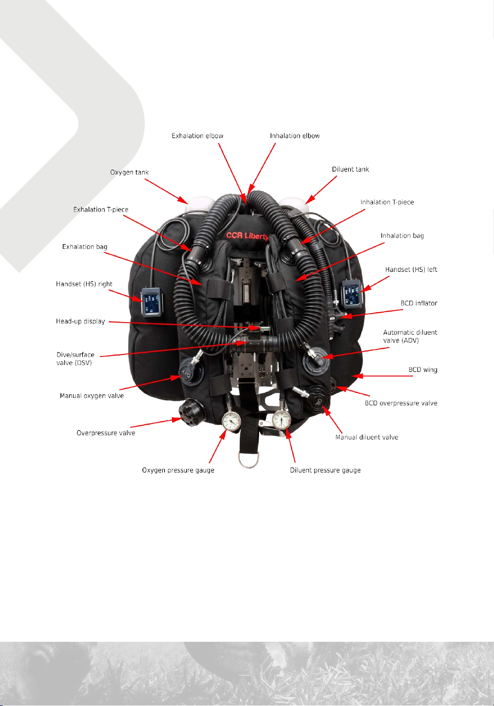
1. Technical design

11

12
1.1 Basic schematic
OXYGEN
DILUENT
CU
CU
HS
HS
Exhalation
bag
Inhalation
bag
Watertrap
CO absorbent
2
ppO sensors
2
Solenoid
valves
Overpressure
valve
Manualoxygenvalve
ADV
Manualdiluentvalve
Pressure
&temperature
sensors
He%
sensors
Dive/surface
valve
Oxygen
reduction
valve
Diluent
reduction
valve
Controlunits
HUD
Buddy
display
Rechargeablebatteries
Displayunits
The principle of a rebreather involves in recycling the breathing mixture. Carbon dioxide is
removed from the exhaled mixture and is again prepared for the next inhalation after being
replenished with oxygen. The composition of the breathing mixture changes continuously.
13
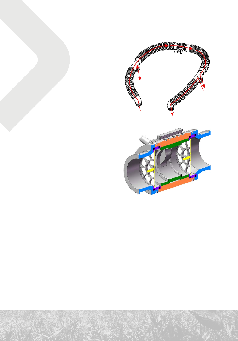
1.2 Dive/surface valve
The breathing mixture is delivered to the
dive/surface valve (DSV) through the
corrugated hose from the left. When inhaling,
the mixture passes through the inhalation
valve to the mouthpiece and then into the
diver’s respiratory tract. When exhaling, it
passes through the exhalation valve into the
corrugated hose on the right.
The direction of the mixture’s flow is indicated
on the DSV.
1.2.1 Inhalation valve
The inhalation valve ensures that the exhaled
mixture does not backflow into the inhalation
bag and is not repeatedly inhaled by the diver
without the removal of carbon dioxide and the
addition of oxygen.
The inhalation valve is situated within the
connection of the left corrugated hose.
A similar mushroom valve can be found in the exhalation valve an open circuits’s second-stage
regulator.
This is one of the most critical components of the rebreather. It is, however, difficult to
detect a malfunction in this part during a dive, and such a malfunction can lead to loss of
consciousness.
1.2.2 Exhalation valve
The exhalation valve directs the exhaled mixture via the corrugated hose to the exhalation bag.
It prevents the diver from directly re-inhaling the exhaled mixture.
The exhalation valve is situated within the connection of the right corrugated hose.

14
Closing the dive/surface valve
If the diver is in the water and not using the
DSV, the DSV must be closed. Otherwise, the
circuit will become flooded with water.
Closing the DSV is done by using the gate
handle situated on the front part of the DSV.
In the open position, the handle is put up; in
the closed position, it is down.
1.2.3 Mouthpiece
Creating a tight seal around the rebreather’s mouthpiece prevents water from entering into
the circuit. The DSV and corrugated hoses function at a greater force than the regulator of
an open-circuit apparatus. Therefore having, an anatomically suitable mouthpiece and proper
clenching of the mouth is critical.
We do not recommend using a mouthpiece that can be shaped to the diver’s bite after heating.
This kind of mouthpiece restricts the movement of the lower jaw, which leads to unilateral
stress and will rapidly exhaust the masseter muscles.
1.2.4 Usage with a full face mask
Even though the mechanical dimensions of the DSV would allow for the connection of
a full face mask, it is not possible to switch an open-circuit mixture inlet with an inlet from
a rebreather. One of the reasons for this is the necessity of defogging the visor.
Consult with the manufacturer regarding possibilities of connecting a full face mask to the
rebreather. The use of such an apparatus will require procedures that deviate from this manual
and from standard procedures taught in a course accredited by the rebreather’s manufacturer.

15
1.3 Corrugated hoses and accessories
1.3.1 Hoses
The corrugated hoses are made of EPDM
rubber. Compatible chemical agents must be
used for cleaning and disinfection (see 104
Cleaning and disinfection).
The corrugated hoses can be damaged if
subjected to excessive stress. In particular, it
is necessary to avoid perforation, cutting, and
excessive wear. Avoid long-term deformation
of the hoses when storing the unit. Do not
treat the hoses like a hanger.
The corrugated hoses are one of the least durable mechanical parts of the CCR Liberty. Pay
appropriate attention to protecting and maintaining them.
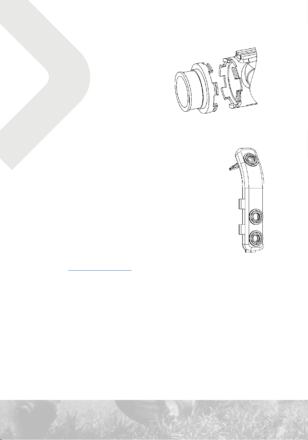
1.3.2 Attachment to the head
Unlike almost all other bayonet connectors
on the CCR Liberty, the bayonet connector on
the exhalation side has three protrusions. This
design prevents incorrect attachment of the
hoses, since the inhalation side has only two
protrusions.
Elbow on the exhalation side (left) and inhalation side (right).
1.3.3 Connection to the breathing bags
The T-pieces have standard bayonet connections. On the
exhalation side, the T-piece has a partition that directs any
water that has entered the DSV to
the exhalation bag and improves
the blending of the mixture when
oxygen is added via the manual
bypass valve.
16
1.3.4 Attachment of the DSV
The DSV attachment to the corrugated hoses
is done with axial teeth that fit together and
are secured with a wire retaining ring.
The baskets of the mushroom valves are
inserted into the connector. When handling
the baskets, pay close attention to their
correct orientation.
1.4 Inhalation bag
The inhalation bag is mounted on the left side of the harness (from the
diver’s perspective when wearing the CCR Liberty).
The external cover is made from a resilient textile, ensuring mechanical
protection. The internal bag is made from polyurethane. It is connected to
the breathing circuit with a T-piece via the upper bulkhead with a bayonet
connector.
The inhalation bag is affixed to the harness with two stainless-steel
buckles and is secured with Velcro flaps. It can be easily removed for
cleaning, disinfecting, and other handling.
See also 104 Cleaning and disinfection.
1.4.1 Automatic diluent valve
The automatic diluent valve (ADV) is mounted in the middle bulkhead with a bayonet connector.
When the volume of the inhalation bag decreases, the ADV is pressed, and diluent is
automatically added to the breathing circuit.
The ADV can be closed by sliding the collar.
The sensitivity of the ADV can be decreased with an additional spring, which is included as
a spare part.

17
1.4.2 Manual diluent bypass valve
The manual diluent bypass valve is situated in the lower bulkhead of the inhalation bag and is
equipped with a bayonet connector.
The valve is attached to the low pressure (LP) hose with a seatec-style quick-release connector.
It is operated by pressing the center button.
The safety lock prevents diluent valve from accidentally falling out. Keep this
information in mind when removing the valve.
1.5 Exhalation bag
The exhalation bag is situated on the right side of the harness. It’s design and
the way it is connected to the harness and to the breathing loop are similar to
that of the inhalation bag.
1.5.1 Manual oxygen bypass valve
The manual oxygen bypass valve is situated in the middle
bulkhead of the exhalation bag and is equipped with a bayonet
connector.
The valve is attached to the intermediate pressure hose with
an oxygen quick-release connector. This connector is like
a standard seatec-style quick-release connector with a collar.
A standard connector cannot be connected to the oxygen quick-
release connector, though, it is possible to connect the oxygen hose to the normal connector.
Do not remove the collar from the oxygen connector as connecting the wrong gas to the wrong
valve could potentially be dangerous. This is a requirement of the EN 14141 norm.
The bayonet connector on the oxygen bypass valve has three protrusions.
Use oxygen-compatible lubricant for maintenance of the oxygen bypass valve (We recommend
DuPont Krytox GPL-226).

18
1.5.2 Overpressure valve
The overpressure valve (OPV) is mounted in the lower bulkhead of
the exhalation bag and is equipped with a bayonet connector.
The required pressure is regulated via rotation. When set to
a minimal pressure (by turning counterclockwise), the valve is
opened; only a mushroom valve ensures minimal overpressure.
A safety lock prevents the OPV from accidentally falling out. To remove the valve push it in to
unlock, and rotate in the direction of the arrows. Indicated on the valve.
1.6 Oxygen tank
1.6.1 Tank
The CCR Liberty uses a three-liter steel tank with 100 mm diameter and has a 200 bar filling
pressure. The original 300 bar filling pressure of the tank was changed according to valid
technical standards.
The tank is labeled OXYGEN and is situated on the diver’s right side when wearing the CCR
Liberty.
When connecting the oxygen tank to the unit, make sure the tank is in an upright orientation
before tightening the handwheel on the oxygen first-stage regulator. Trying to straighten the
cylinder when it is already screwed in will put tension on the threats and will be hard to remove
without the help of tools.
For more information on filling, see 85 Oxygen.

19
1.6.2 Valve
The oxygen tank valve has a M26×2 200 bar outlet connection. The valve is not compatible with
standard DIN valves to eliminate possible mix-up between oxygen and diluent bottles, this is
a requirement of the EN 14141 norm.
1.6.3 Reduction valve
The CCR Liberty uses an Apeks DST4 first-stage regulator with a specially made low-pressure
turret mounted on the backplate that serves as a lower tank-mounting point. A Velcro strap
wraps around the middle of the tank to secure it to the unit.
The reduction valve is equipped with an intermediate-pressure safety overpressure valve.
1.6.4 Pressure reading
The oxygen pressure gauge is situated on the diver’s right side; the HP hose runs through an
opening in the backplate.
1.7 Diluent tank
1.7.1 Tank
The CCR Liberty uses a three-liter steel tank with 100 mm diameter and 230 bar filling
pressure. The original 300 bar filling pressure of the tank was changed due to utilizing a
230 bar valve.
The tank is labeled DILUENT and is situated on the diver’s left side when wearing the CCR
Liberty.
For more information on filling, see 84 Diluent.
1.7.2 Valve
The diluent cylinder valve has a DIN G 5/8” 230 bar outlet connection.
1.7.3 Reduction valve and pressure reading
The design is similar to that of the oxygen tank, only mirrored.
Table of contents
Other Divesoft Diving Instrument manuals


Popular Diving Instrument manuals by other brands


Dive Rite
Dive Rite Transpac II owner's manual

Aqua Lung
Aqua Lung Airsource owner's manual

Sherwood Scuba
Sherwood Scuba 9000 SERIES Service manual

SUBMERSIBLE SYSTEMS
SUBMERSIBLE SYSTEMS HEED 3 Technical user's manual

DIVEX
DIVEX DIVEX ULTRALITE 2 E12380 Operating and maintenance manual

Sealife
Sealife SeaDragon 1500F instruction manual