Cleanburn 14336 User guide
CLEAN BURN MODEL: DOUBLE-PISTON AIR COMPRESSOR #14336
OptionalAccessoriesforCleanBurnFurnaces/Boilers
INSTALLER'S MANUAL
PUBLICATION DATE: 1/4/10, Rev. 5 CLEAN BURN PART # 43142
IMPORTANTFORU.S.INSTALLATIONS: Allinstallationsmustbemadeinaccordancewithstateandlocalcodeswhich
maydifferfromtheinformationprovidedinthismanual. Savetheseinstructionsforreference.
IMPORTANTFORCANADIANINSTALLATIONS: Theinstallationofthisequipmentistobeaccomplishedbyqualified
personnelandinaccordancewiththeregulationofauthoritieshavingjurisdictionandCSAStandardB139,Installation
CodeforOilBurningEquipment.
I89056


WARRANTY INFORMATION
CleanBurn,Inc.,MANUFACTURER,herebywarrantsthatMANUFACTURER'sproductsshallbefreefromdefectinmaterial
and workmanship under normal use according to the provisions and limitations herein set forth.
MANUFACTURERwarrantstheheatexchanger/combustionchamberforaperiodoften(10)years(or15,000hours,
whichever comes first), from the date of purchase by the purchaser, as follows:
If the defect occurs in the first five (5) years (or 7500 hours, whichever comes first) , Clean Burn pays 100% of parts,
replacement or repair (the customer pays 0%), and pro rata thereafter according to the following schedule:
(a) If the defect occurs during the sixth year (or 7500-9000 hours, whichever comes first), customer pays 70% of
parts,replacementor repair.
(b) If the defect occurs during the seventh year (or 9000-10,500 hours, whichever comes first), customer pays 75%
of parts, replacement or repair.
(c) If the defect occurs during the eighth year (or 10,500-12,000 hours, whichever comes first), customer pays 80%
of parts, replacement or repair.
(d) If the defect occurs during the ninth year (or 12,000-13,500 hours, whichever comes first), customer pays 85% of
parts,replacementor repair.
(e) If the defect occurs during the tenth year (or 13,500-15,000 hours, whichever comes first), customer pays 90% of
parts,replacementor repair.
MANUFACTURERwarrantsallotherCleanBurncomponentparts,includingtheenergyretentiondisk,foraperiodofone
(1) year from the date of purchase by the purchaser.
LIMITATIONS:
The obligation of MANUFACTURER for breach of warranty shall be limited to products manufactured by MANUFACTURER (1) that
are installed, operated and maintained according to MANUFACTURER's instructions furnished and/or available to the purchaser upon
request; (2) that are installed according to all other applicable Federal, State and local codes or regulations; and (3) that the purchaser
substantiates were defective in material and workmanship notwithstanding that they were properly installed and correctly maintained as set
forth above and were not abused or misused.
The obligation of MANUFACTURER shall be limited to replacing or repairing the defective product, at the option of the
MANUFACTURER. MANUFACTURER shall not be responsible for any labor or costs of removal or reinstallation of its products and
shall not be liable for transportation costs to and from its plant at Leola, Pennsylvania.
Use of parts for modification or repair of the product or any component part thereof not authorized or manufactured by
MANUFACTURER specifically for such product shall void this warranty.
This warranty shall not apply to any damage to or defect in any of MANUFACTURER's products that is directly or indirectly caused by
(1) force majeure, Act of God or other accident not related to an inherent product defect; or (2) abuse, misuse or neglect of such product,
including any damage caused by improper assembly, installation, adjustment, service, maintenance or faulty instruction of the purchaser.
Other than as expressly set forth hereinabove, MANUFACTURER makes no other warranty, express or implied, with respect to any of
MANUFACTURER's products, including but not limited to any warranty of merchantability or fitness for a particular purpose.
And in no event shall MANUFACTURER be responsible for any incidental or consequential damages of any nature suffered by purchaser
or any other person or entity caused in whole or in part by any defect in any of MANUFACTURER's products. Any person or entity to
whom this warranty extends and who claims breach of warranty against MANUFACTURER must bring suit thereon within one year from
the date of occurrence of such breach of warranty or be forever barred from any and all legal or other remedies for such breach of warranty.
MANUFACTURER is not responsible for and hereby disclaims any undertaking, representation or warranty made by any dealer,
distributor or other person that is inconsistent with or in any way more expansive than the provisions of this limited warranty.
This warranty grants specific legal rights and shall be read in conformity with applicable state law. In some jurisdictions, the applicable law
mandates warranty provisions that provide greater legal rights than those provided for herein. In such case, this limited warranty shall be
read to include such mandated provisions; and any provision herein that is prohibited or unenforceable in any such jurisdiction shall, as to
such jurisdiction, be ineffective to the extent of such prohibition or unenforceability without invalidating the remaining provisions and
without affecting the validity or enforceability of such provision in any other jurisdiction(s).

TRADEMARKS
The Clean Burn logo is a trademark of Clean Burn, Inc. All other brand or product names mentioned are the registered
trademarks or trademarks of their respective owners.
COPYRIGHT
Copyright © 2010 Clean Burn, Inc. All rights reserved. No part of this publication may be reproduced, or distributed without
thepriorwrittenpermissionofCleanBurn,Inc. 34ZimmermanRoad,Leola,PA 17540. Subjecttochangewithoutnotice.

TABLE OF CONTENTS
NOTE: A Special Bulletin (which appears just after the Table of Contents) has been
added to your manual to highlight important information about the installation,
adjustment and operation of your air compressor. Be sure to read this sheet before
beginning any procedures in this manual.
SECTION 1: INTRODUCTION ................................................................................... 1-1
GuidetothisManual ..........................................................................................................1-1
ForYourSafety... ..............................................................................................................1-2
SECTION 2: UNPACKING ......................................................................................... 2-1
UnpackingandInspectingAllComponents .........................................................................2-1
SECTION 3: INSTALLING THE AIR COMPRESSOR ............................................... 3-1
AirCompressorExplodedViewwithPartsList ..................................................................3-2
InstallingtheAirCompressorComponents .........................................................................3-3
PreparingtheFurnaceCabinet(Saturn140/Saturn240)....................................................3-5
MountingtheAirCompressor(Saturn140/Saturn240) ....................................................3-5
PreparingtheFurnaceCabinet(CB-1750/CB-2500/CB-3250) ......................................3-7
MountingtheAirCompressor(CB-1750/CB-2500/CB-3250).......................................3-7
PreparingtheFurnaceCabinet(CB-3500/CB-5000)........................................................3-9
MountingtheAirCompressor(CB-3500/CB-5000) ........................................................3-9
MountingtheAirCompressor(CB-200-CTB/CB-350-CTB/CB-500-CTB)..................3-9
PreparingtheCB-500SeriesBurnerforusewiththeAirCompressor ...............................3-10
ConnectingtheAirCompressortotheCB-500SeriesBurner ...........................................3-12
WiringtheAirCompressortotheCB-500SeriesBurner ..................................................3-12
PreparingtheSaturnBurnerforusewiththeAirCompressor ............................................3-13
ConnectingtheAirCompressortotheSaturnBurner ........................................................3-14
WiringtheAirCompressortotheSaturnBurner ...............................................................3-14
SECTION 4: OPERATING & MAINTAINING THE AIR COMPRESSOR ...................4-1
AdjustingtheAirCompressorduringOperation ..................................................................4-1
MaintainingtheAirCompressor .........................................................................................4-2
APPENDIX A
TechnicalReferenceMaterials ........................................................................................... A-1
CB-500SeriesBurnerWiringDiagram ....................................................................... A-1
SaturnBurnerWiringDiagram .................................................................................... A-2
AirCompressorWiring .............................................................................................. A-3


SPECIAL BULLETIN
CleanBurnModel#14336isadouble-pistonaircompressorwhichcanbeinstalledonALLClean
Burnfurnaceandboilermodels.
IMPORTANT INFORMATION CONCERNING THE SERVICE RATING
OF THE AIR COMPRESSOR
Aircompressormodel#14336hasaserviceratingofapproximately75%. Thismeansthattheaircompressor
canoperatecontinuouslyforapproximately45minutes(75%ofonehour),andthenitmustnotoperatefor
approximately15minutes(25%ofonehour)toallowtheaircompressorto"cooldown." Thisworkswellfor
mostfurnace/boilerinstallationswheretheunitwillcycleonandoffafewtimesduringanhour.
CAUTION: If the furnace/boiler will run continuously (without cycling on and off a few times
during an hour), you must use an air compressor with a tank. (Refer to the air compressor specifications
foryourfurnace/boilerwhenpurchasinganaircompressorwithatank.) DONOTuseaircompressormodel
#14336 if your furnace/boiler will run continuously for periods which exceed the 75% service rating.
Thiswilloverheattheaircompressorandseverelydamagetheteflonringsandteflonskirtintheaircompressor,
resultinginpoorairpressureoutputfromthecompressor.
IMPORTANT INFORMATION CONCERNING ADJUSTMENT
OF THE AIR COMPRESSOR
Itisveryimportanttofollowtheinstructions"AdjustingtheAirCompressorDuringOperation"inthis
manual. Thisprocedureinvolvestheadjustmentofthepressurereliefontheaircompressorsothattheprecise
airpressure(12to18psi)requiredforproperburneroperationisprovidedtotheburner. Excessairpressure
isbledoffthroughthepressurerelief.
CAUTION: DONOTruntheaircompressorwithoutproperlyadjustingthepressurerelief. Thiswilloverheat
theaircompressorandseverelydamagetheteflonringsandteflonskirtintheaircompressor,resultinginpoor
airpressureoutputfromthecompressor.
IMPORTANT INFORMATION CONCERNING YOUR
AIR COMPRESSOR MODEL


Installer's Manual: Clean Burn Air Compressors
1-1
SECTION 1: INTRODUCTION
Guide to this Manual
IMPORTANT! This manual provides all the instructions necessary to install the Clean Burn
air compressor on your Clean Burn furnace or boiler. Refer to your equipment Operator's Manual
for instructions on assembling, installing, operating, and maintaining your furnace or boiler.
Consult the Table of Contents for a detailed list of topics covered in this manual. You'll find the step-
by-step procedures easy to follow and understand. Should questions arise, please contact your Clean
Burn dealer before starting any of the procedures in this manual.
Following is an outline of the air compressor installation process:
•UNPACKING
• INSTALLINGTHEAIRCOMPRESSOR
• InstallingtheAirCompressorComponents
• PreparingtheFurnaceCabinet
• MountingtheAirCompressor(Furnaces)
• MountingtheAirCompressor(Boilers)
• PreparingtheBurnerforusewiththeAirCompressor
• ConnectingtheAirCompressortotheBurner
• WiringtheAirCompressor
Proceduresarealsoprovidedforadjustingtheaircompressorduringfurnace/boileroperationandfor
maintainingtheaircompressor.
Please read all sections carefully--including the following safety information--before beginning any
installation procedures; doing so ensures your safety and the optimal performance of your Clean
Burn air compressor.
Installer's Manual: Clean Burn Air Compressors
1-2
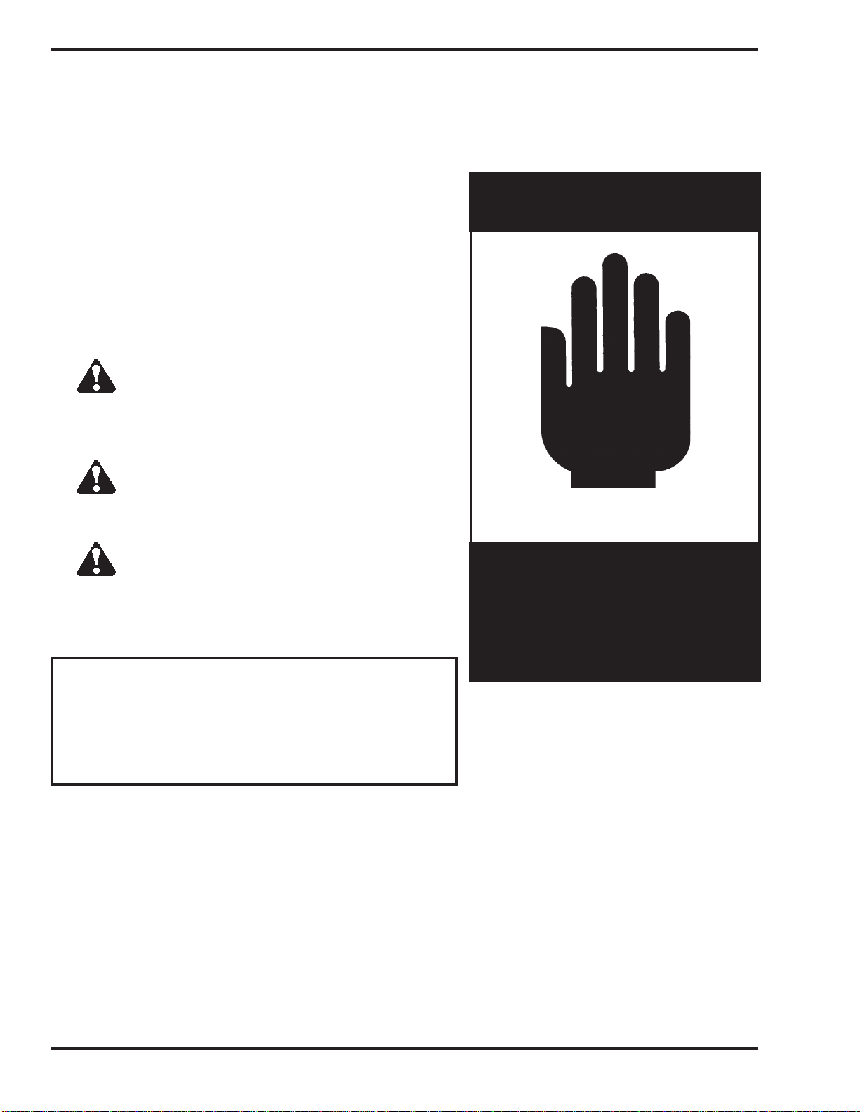
For Your Safety...
IMPORTANT! Review the list of general safety
precautionsprovidedinSection1ofyourFurnace/
BoilerOperator'sManual. Theseprecautionsmust
be heeded toensureproper,safe air compressorand
furnace/boileroperation.
WARNING!
STOP
YOUR SAFETY IS AT STAKE!
DO NOT INSTALL, OPERATE, OR
MAINTAIN THIS EQUIPMENT
WITHOUT FIRST READING
AND UNDERSTANDING
THIS MANUAL!
Please read all sections in this manual carefully--including the following safety information--before
beginning any installation procedures; doing so ensures your safety and the optimal performance of
your Clean Burn air compressor and furnace/boiler.
For your safety, Clean Burn documentation contains the
following types of safety statements (listed here in order
of increasing intensity):
•NOTE: A clarification of previous
information or additional pertinent
information.
•ATTENTION: A safety statement
indicating that potential equipment damage
may occur if instructions are not followed.
CAUTION: A safety statement
that reminds of safety practices or directs
attention to unsafe practices which could
result in personal injury if proper
precautions are not taken.
WARNING: A strong safety
statement indicating that a hazard exists
which can result in injury or death if proper
precautions are not taken.
DANGER! The utmost levels of
safety must be observed; an extreme hazard
exists which would result in high probability
of death or irreparable serious personal
injury if proper precautions are not taken.

Installer's Manual: Clean Burn Air Compressors
2-1
SECTION 2: UNPACKING
Beforeinstallingtheaircompressoronyourfurnace/boiler,youshouldtakesometimetocarefullyunpackyour
shipment from Clean Burn.
Carefully open all shipping containers and inspect all components. Immediately notify the freight
company and your Clean Burn dealer in case of shipping damage or shortage(s). Keep all components
together so you will have them as needed for assembly and installation.
For your convenience, air compressor components are listed in Section 3 (in related groupings)
throughout the installation process. Detailed illustrations with labelled components should enable
easy assembly/installation.
Unpacking and Inspecting All Components

Installer's Manual: Clean Burn Air Compressors
2-2

Installer's Manual: Clean Burn Air Compressors
3-1
SECTION 3: INSTALLING THE AIR COMPRESSOR
IMPORTANT! If you are installing your furnace/boiler and air compressor at the same time, Clean
Burnrecommendsthefollowingsequenceofactivities:
1. AssemblyofFurnace/Boiler(forfurnace-throughtheinstallationofmounting/stabilizerbrackets).
2. InstallationofAirCompressoronFurnace/Boiler
3. InstallationofFurnace/Boiler(includingoilpump,wiring,oil/airlines,stack,thermostat)
KeeptheFurnace/BoilerOperator'sManualhandyforquickreferenceasspecifiedthroughouttheinstallationof
theaircompressor.
WARNING: If you have already installed your furnace/boiler and power has been connected
totheunit,ensurethatthepoweristurnedOFFbeforeproceedingwiththeinstallationoftheair
compressortoavoidelectricalshockhazards.
Installer's Manual: Clean Burn Air Compressors
3-2
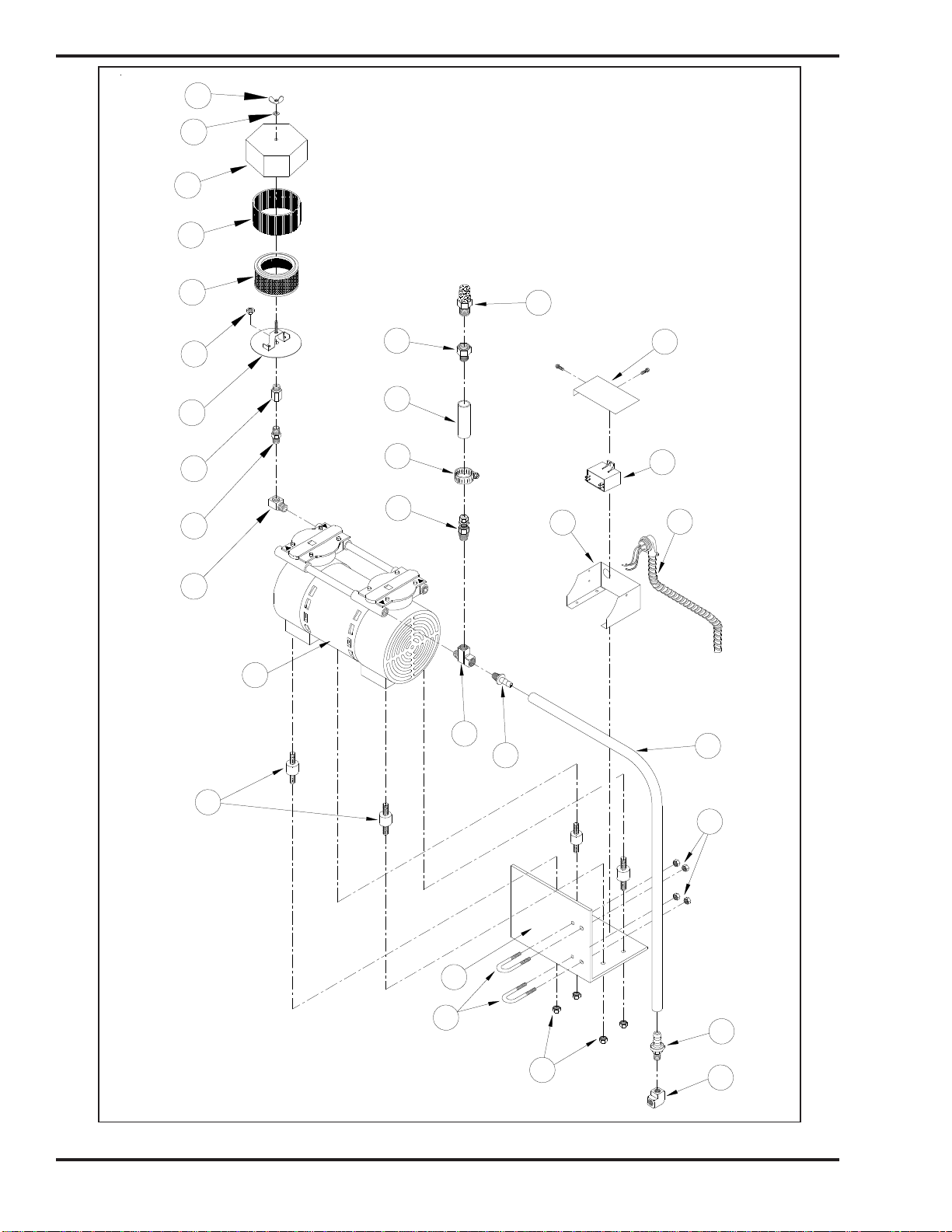
Figure3A-AirCompressorExplodedView
I89055
30
1
4
10
25
12
6
8
7
9
2
3
11
24
26
28
27
29
17
14
16
15
22
18
19
20
21
23
13
5

Installer's Manual: Clean Burn Air Compressors
3-3
ITEM QTY PART# DESCRIPTION
1 1 32280 1/8" ELBOW 90°
2 1 32234 HOSE BARB (3/8" H x 1/8"NPT)
3 1 54063 AIR HOSE (3/8",42" LONG)
4 1 32236 HOSE BARB(3/8"H x 1/4" NPT)
5 1 32233 BRASS STREET TEE (1/4" NPT)
6 1 32146 RELIEF VALVE
7 1 32091 HOSE CLAMP
8 1 13063 AIR HOSE (3/8" ID, 3" LONG)
9 1 32147 PIPE ADAPTER (1/2" x 3/8")
10 32157 MUFFLER
11 4 34092 1/4−20 NUT
12 1 12177 POWER CABLE
13 1 32518 AIR COMPRESSOR− DUAL PISTON (75R)
14 1 32210 1/4 BRASS STREET ELBOW
15 1 32150 1/4 BRASS NIPPLE
16 1 32411 1/4NPT F TO 3/8NPS BULKHEAD FITTING
17 1 70341 BASE PLATE
18 1 32412 3/8 NPS BULKHEAD NUT
19 1 32409 FILTER ELEMENT
20 1 N/A PART OF 32409
21 1 21130 FILTER HOUSING
22 1 34182 1/4" VINYL WASHER
23 1 34181 1/4" WING NUT
24 4 31104 VIBRATION INSULATOR
25 2 21075 "U" BOLT
26 1 25120 MOUNTING PLATE
1
29 1 21180 ELECTRICAL BOX COVER
28 1 33383 CAPACITOR
27 1 21179 ELECTRICAL BOX
30 4 34009 3/8−16 NUT
1. RefertoFigure3A.
2. Installtheairintakefilterintheinletportonthecompressorhead(noticethedirectionalarrow).
3. Installthe1/4"streetteeintheoutletportofthecompressorhead(noticethedirectionalarrow).
4. Install the relief valve on the street tee.
5. Install the hose clamp and 3/8" x 3" air hose. Then install the 3/8" x 1/2" bushing and muffler on
the relief valve.
6. Leavethehoseclamploosetoallowforinitialadjustmentofthereliefvalve(Section4).
7. Install the 3/8" H x 1/4" NPT hose barb on the street tee.
Installing the Air Compressor Components

Installer's Manual: Clean Burn Air Compressors
3-4
Figure3B-AirCompressorInstalledontheSaturn140/Saturn240
I89060

Installer's Manual: Clean Burn Air Compressors
3-5
Preparing the Furnace Cabinet (Furnace Models Saturn 140 / 240)
1. RefertoFigures3Aand3B.
2. Installall-threadrodsthroughthemountingholesinthebaseandtopofthefurnacecabinet. Usedouble
nutstosecurelylocktheall-threadrodsinposition.
Mounting the Air Compressor (Furnace Models Saturn 140 / 240)
CAUTION: Thecompressormustbesecurelymountedasdescribedinthissection. Ensurethat
all nuts and bolts are firmly tightened.
1. RefertoFigure3Aand3B.
2. Whilefacingtheburnersideofthefurnace,installtheaircompressoronthefrontrightall-threadrod
usingthetwoU-boltsandnutsprovided. Positionthemountingbracketapproximatelytwoinches
abovethetopofthefurnacecabinet.

Installer's Manual: Clean Burn Air Compressors
3-6
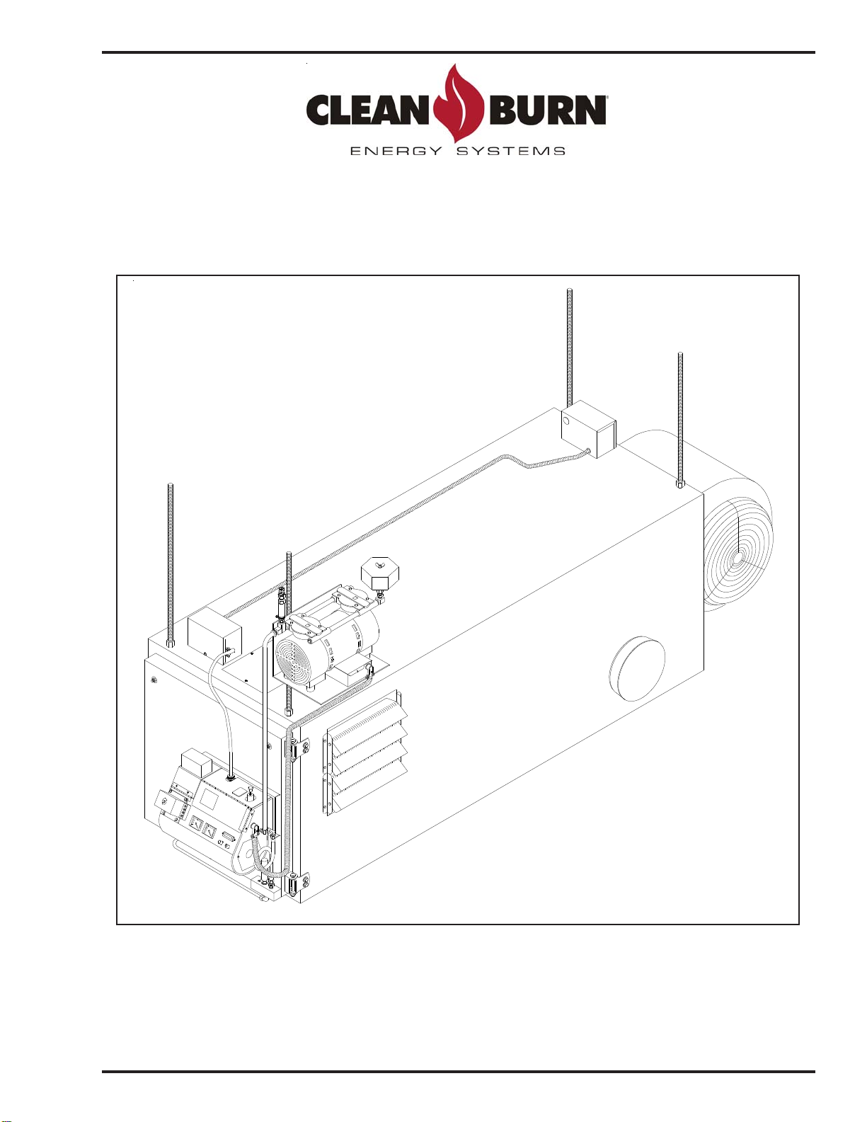
Figure3C-AirCompressorInstalled on the CB-1750 / CB-2500/CB-3250
I89056

Installer's Manual: Clean Burn Air Compressors
3-7
Preparing the Furnace Cabinet (Furnace Models CB-1750/2500/3250)
1. RefertoFigures3Aand3C.
2. Installall-threadrodsinthemountinglugsontopofthefurnacecabinet. Usedoublenutsto
securely lock the all-thread rods in position.
Mounting the Air Compressor (Furnace Models CB-1750/2500/3250)
CAUTION: Thecompressormustbesecurelymountedasdescribedinthissection. Ensurethat
all nuts and bolts are firmly tightened.
1. RefertoFigure3Aand3C.
2. Whilefacingtheburnersideofthefurnace,installtheaircompressoronthefrontrightall-threadrod
usingthetwoU-boltsandnutsprovided. Positionthemountingbracketapproximatelytwoinches
abovethetopofthefurnacecabinet.

Installer's Manual: Clean Burn Air Compressors
3-8
Figure3D-AirCompressorInstalledontheCB-3500/CB-5000
I89058
Table of contents
Popular Air Compressor manuals by other brands

Bend-Pak
Bend-Pak RS7580H603 Installation and operation manual

Central Pneumatic
Central Pneumatic CENTRAL PNEUMATIC 95499 Assembly and operation instructions

Champion
Champion 30000 Owner's and operator's manual

Vmac
Vmac UNDERHOOD 40 Series installation manual

Schulz
Schulz 20120HWV80X owner's manual

Craftsman
Craftsman 919.727580 owner's manual


Gardner Denver
Gardner Denver ELECTRA-SCREW 60 HP Service manual

Panasonic
Panasonic SD51C10JAU6 Specification sheet

DeWalt
DeWalt XR FLEXVOLT LI-ION DCC1054 Original instructions

MY PROJECT
MY PROJECT MPKT 60 B2 Operation and safety notes translation of the original instructions

VITO
VITO PRO-POWER VICO50A instruction manual

Sealey
Sealey SAC20030B quick start guide