CleanDigital PSU12 User manual

PSU12
Integrated Switching Power Supply
All Rights Reserved
Version: PSU12_2016V1.0
User Manual

Integrated Switching Power Supply
Preface
Read this user manual carefully before using this product. Pictures shown in this
manual is for reference only, different model and specifications are subject to real
product.
This manual is only for operation instruction only, not for any maintenance usage. The
functions described in this version are updated till August 2016. In the constant effort to
improve our product, we reserve the right to make functions or parameters changes
without notice or obligation. Please refer to the dealers for the latest details.
All product function is valid till 2016-8-15.
Trademarks
Product model and logo are trademarks. Any other trademarks mentioned in this
manual are acknowledged as the properties of the trademark owner. No part of this
publication may be copied or reproduced without the prior written consent.
FCC Statement
This equipment generates, uses and can radiate radio frequency energy and, if not
installed and used in accordance with the instructions, may cause harmful interference
to radio communications. It has been tested and found to comply with the limits for a
Class B digital device, pursuant to part 15 of the FCC Rules. These limits are designed
to provide reasonable protection against harmful interference in a commercial
installation.
Operation of this equipment in a residential area is likely to cause interference, in which
case the user at their own expense will be required to take whatever measures may be
necessary to correct the interference.
Any changes or modifications not expressly approved by the manufacture would void
the user’s authority to operate the equipment.

Integrated Switching Power Supply
SAFETY PRECAUTIONS
To insure the best f r o m t h e p roduct, please read all i n s t ructions carefully b e f o r e u s i n g
the device. Save this manual for further reference.
l Unpack the equipment carefully and save the original box and packing material for
possible future shipment
l Follow basic safety precautions to reduce the risk of fire, electrical shock and injury
to persons.
l Do not dismantle the housing or modify the module. It may result in electrical shock
or burn.
l Using supplies or parts not meeting the products’ specifications may cause
damage, deterioration or malfunction.
l Refer all servicing to qualified service personnel.
l To prevent fire o r s h o c k h a z a r d , do not expose the unit t o r a in, moisture or in s t a l l
this product near water.
l Do not put any heavy items on the extension cable in case of extrusion.
l Do not remove the housing of the device as opening or removing housing may
expose you to dangerous voltage or other hazards.
l Install the device in a place with fine ventilation to avoid damage caused by
overheat.
l Keep the module away from liquids.
l Spillage into the housing may result in fire, electrical shock, or equipment damage.
If an object or liquid falls or spills on to the housing, unplug the module immediately.
l Do not twist or pull by force ends of the optical cable. It can cause malfunction.
l Do not use liquid or aerosol cleaners to clean this unit. Always unplug the power to
the device before cleaning.
l Unplug the power cord when left unused for a long period of time.
l Information on disposal for scrapped devices: do not burn or mix with general
household waste, please treat them as normal electrical wastes.

Integrated Switching Power Supply
Contents
1. Introduction .................................................................................................................. 1!
1.1 Brief Introduction ................................................................................................ 1!
1.2 Features ............................................................................................................. 1!
1.3 Package List ....................................................................................................... 1!
2. Panel Description ........................................................................................................ 2!
2.1 Front Panel ......................................................................................................... 2!
2.2 Rear Panel ......................................................................................................... 2!
3. System Connection ..................................................................................................... 4!
3.1 Usage Precautions ............................................................................................. 4!
3.2 System Diagram ................................................................................................. 4!
3.3 Connection Procedure ....................................................................................... 4!
4. System Operations ...................................................................................................... 5!
4.1 Front Panel Buttons ........................................................................................... 5!
4.2 RS232 Control .................................................................................................... 5!
4.2.1 Installation/uninstallation of RS232 Control Software .............................. 5!
4.2.2 Basic Settings .......................................................................................... 5!
4.2.3 RS232 Communication Commands ......................................................... 6!
4.3 Web-based GUI Control ..................................................................................... 9!
4.3.1 Control Menu ......................................................................................... 10!
4.3.2 Voltage Setting Menu ............................................................................. 11!
4.3.3 Network Menu ........................................................................................ 11!
4.3.4 Password Menu ..................................................................................... 12!
4.3.5 Web-based GUI Update ......................................................................... 13!
5. Specification .............................................................................................................. 14!
6. Panel Drawing ........................................................................................................... 15!
7. Troubleshooting & Maintenance .................................................................................. 1!
8. After-sales Service ...................................................................................................... 3!

Integrated Switching Power Supply
1
1. Introduction
1.1 Brief Introduction
The product is an integrated switching power supply designed for converting AC into
DC power. It provide 2 input channels and 12 output channels, input voltage
100~240VAC, output 5/12/24VDC, the max power consumption of single channel is
15W.
Base on the sequential control technology, when power on, the 12 output channels will
turned on orderly every 100ms.In addition, each output channel also can be switch
on/off via front panel button, RS232 commands or Web-based GUI, and the output
voltage on each output channel can be selected as 5/12/24V DC via the TACT Switch
on rear panel, RS232 command, or web-based GUI.
1.2 Features
l Double input channel designed for ensuring the stable AC source.
l Total 12 output channels, and each channel has three kinds of output voltage
(5/12/24VDC) can be selected.
l Output channels can be switch on/off by via the front panel buttons, RS232
commands or Web-based GUI.
l Output voltage (5/12/24VDC) can be selected via the TACT Switch on rear
panel, RS232 commands, or web-based GUI.
l Adopt sequential control technology.
l Supports online software upgrading.
1.3 Package List
l 1 x Integrated Switching Power Supply
l 1 x Power Cable
l 12 x 2-Pin phoenix connectors
l 1 x 3-Pin phoenix connector
l 1 x RS232 cable (DB9 to 3-Pin phoenix connector)
l 2 x DC cables
Note
:
Please confirm if the product and the accessories are all included, if not, please
contact with the dealers.

Integrated Switching Power Supply
2
2. Panel Description
2.1 Front Panel
No.
Name
Description
①
FIRMWARE
USB port for updating system firmware.
②
AC1 & AC2
Input AC source indicators.
l Off when there is no power to the device
l Red when the device is in standby mode
l Green when the device is powered on and normal
output.
③
01~12
Output channel switching buttons and Activity LEDs, 12 in
total.
Press the button to trun on/off the corresponding channel,and
the corresponding LED will turn green and keep on.
Note: Pictures shown in this manual are for reference only, different model and
specifications are subject to real product.
2.2 Rear Panel
FIRMWARE
01 02 03 04 05 06
07 08 09 10 11 12
AC 2
AC 1
PSU12
12 3
C
24V
+
DC
12V
5V
+
SELECT
AC100V 240V-
Tx Rx
RS232 TCP IP/
24V
+
AC100V 240V-
AC1 AC2
DC
12V
5V
+ ++ ++ ++ ++ ++ ++ ++ ++ ++ ++ ++
SELECT
24V
DC
12V
5V
SELECT
24V
DC
12V
5V
SELECT
24V
DC
12V
5V
SELECT
24V
DC
12V
5V
SELECT
24V
DC
12V
5V
SELECT
24V
DC
12V
5V
SELECT
24V
DC
12V
5V
SELECT
24V
DC
12V
5V
SELECT
24V
DC
12V
5V
SELECT
24V
DC
12V
5V
SELECT
24V
DC
12V
5V
SELECT
1
A
B
234

Integrated Switching Power Supply
3
No.
Name
Description
①
01~12
12 output channals.
A. DC: 2-Pin phoenix connector, connect with the device
needed to be powered.
B. SELECT: Press the TACT Switch to select the output
voltage as 5/12/24VDC.
C. 5/12/24V indicators: The green indicator of the current
selected output voltage will blink slowly and and keep
on.
②
RS232
Serial port, 3-Pin phoenix connector, connect with a control
device (such as PC) to control the product via RS232
commands.
③
TCP/IP
Ethernet port, connect with PC to control the product via
Web-based GUI.
④
AC1& AC2
2 AC input channels. Input voltage is AC100~240V.
Note: Pictures shown in this manual are for reference only, different model and
specifications are subject to real product.

Integrated Switching Power Supply
4
3. System Connection
3.1 Usage Precautions
l
System should be installed in a clean environment and has appropriate
temperature and humidity control.
l
All of the power switches, plugs, sockets and power cords should be insulated
and safe.
l
All devices should be connected before power on.
3.2 System Diagram
3.3 Connection Procedure
Step1. Connect the devices needed to be powered to the DC ports on rear panel.
Step2. Connect the PC to the RS232 port on rear panel.
Step3. Connect the PC to the TCP/IP port on the rear panel.
Step4. Connect the power cables to the one or both of AC1 and AC2 input port.
AC100V 240V-
Tx Rx
RS232 TCP IP/
24V
+
AC100V 240V-
AC1 AC2
DC
12V
5V
+ ++ ++ ++ ++ ++ ++ ++ ++ ++ ++ ++
SELECT
24V
DC
12V
5V
SELECT
24V
DC
12V
5V
SELECT
24V
DC
12V
5V
SELECT
24V
DC
12V
5V
SELECT
24V
DC
12V
5V
SELECT
24V
DC
12V
5V
SELECT
24V
DC
12V
5V
SELECT
24V
DC
12V
5V
SELECT
24V
DC
12V
5V
SELECT
24V
DC
12V
5V
SELECT
24V
DC
12V
5V
SELECT
Powered Device 1 Powered Device 2 Powered Device 3
100~240VAC
RS232 Control
TCP IP Control/
Power Supply

Integrated Switching Power Supply
5
4. System Operations
4.1 Front Panel Buttons
l Switch on/off output channels:
Press 01~12 buttons on front panel to switch on/off the corresponding output channel.
l Select the output voltage:
Press SELECT button on corresponding output channel to select the output voltage as
5V, 12V or 24V.
After switching the output voltage, the output channel will be turned off based on
overvoltage protection control, and it needs to be turned on via the corresponding
output channel switching button on front panel.
4.2 RS232 Control
Connect a PC to the RS232 port on the rear panel, and then install the RS232 control
software on the PC, the product can be controlled by sending RS232 commands via
the RS232 control software.
4.2.1 Installation/uninstallation of RS232 Control Software
l Installation Copy the control software file to the computer connected with the
product.
l Uninstallation Delete all the control software files in corresponding file path.
4.2.2 Basic Settings
Double-click the software icon to run this software.
Here we take the software CommWatch.exe as example. The icon is showed as
below:
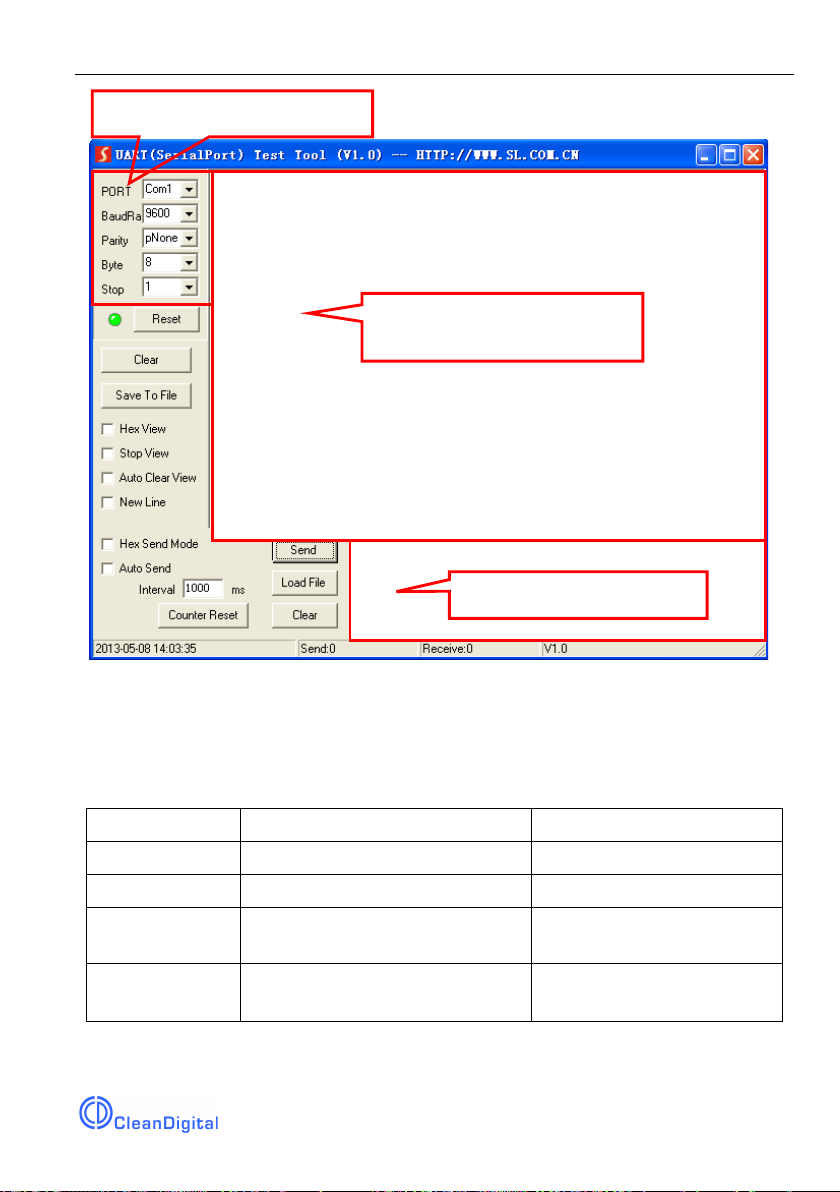
The interface of the control software is showed as below:
Integrated Switching Power Supply
6
Please set the parameters of COM number, baud rate, data bit, stop bit and the parity
bit correctly, and then you are able to send command in Command Sending Area.
4.2.3 RS232 Communication Commands
Communication protocol: RS232 Communication Protocol
Baud rate: 9600 Data bit: 8 Stop bit: 1 Parity bit: none
Command
Function
Feedback Example
All@.
Switch on all output channels.
All Open.
All$.
Switch off all output channels.
All Closed.
[x]@.
Switch on the output channel [x],
x =1~12.
[x] Open.
[x]$.
Switch off the output channel [x],
x =1~12.
[x] Closed.
Parameter Configuration area
Monitoring area, indicates if
the command sent works.
Command Sending area

Integrated Switching Power Supply
7
Command
Function
Feedback Example
Output/[x]V/[y].
When y = NULL, Set the output
voltage as x for all output
channels.
x =5/12/24.
All Output [x]V.
When y =1~12, Set the output
voltage as X for the output
channel y.
x =5/12/24.
[y] Output [x]V.
Status[x].
When x = NULL, query the on-off
status of all output channels.
01 Open.
02 Closed.
03 Closed.
…
When x = 1~12, query the on-off
status of the output channel x.
[x] Open.
[x] Closed.
Save[x].
Save the current on-off status to
Group x. x =1~5.
Save To F[x].
Recall[x].
Invoke the on-off status of Group
x. x =1~5.
If Group x has no data, the
feedback information:
F[x] no data.
If Group x has data, the
feedback information:
Recall From F[x].
Out 01 02 03 04 05 06 07
08 09 10 11 12
State S S S S S S S S S S S
S
Vm 12 12 12 12 12 12 12 12
12 12 12 12
Over N N N N N N N N N N
N N
Clear[x].
When x =NULL, clear the data of
all Group.
Clear All.

Integrated Switching Power Supply
8
Command
Function
Feedback Example
When x =1~5, clear the data of the
Group x.
Clear F[x].
QueryGroup[x].
When x = NULL, query all groups.
Out 01 02 03 04 05 06 07
08 09 10 11 12
Vm1 12 12 12 12 12 12 12
12 12 12 12 12
Vm2 XX XX XX XX XX XX
XX XX XX XX XX XX
……
When x = 1~5, query the group x.
Out 01 02 03 04 05 06 07
08 09 10 11 12
Vm[x] 12 12 12 12 12 12 12
12 12 12 12 12
%0911.
Restore Factory Defaults.
Factory Default
/*Name;
Query the manufacturer.
XXX
/*Type;
Query the product model
PSU12
/^Version;
Query the software version.
V x. x. x
Baud[x].
Set the baud rate as x. x = 1200,
2400,4800,9600,19200,38400,
57600,115200.
When x =NULL, the default baud
rate is 9600.
Baud [x] not change.
Baud [y] change to [x].
%0964.
Query the IP address.
IP XXXX
Note: After sending the “Output/[x]V/[y].” to change the output voltage, the
corresponding output channel will be switch off, the command “[x]@.” should be sent
to switch on this output channel again.
Integrated Switching Power Supply
9
4.3 Web-based GUI Control
In addition to control the product via front panel button and RS232 communication
software. This product can be controlled via web-based GUI. It allows users to interact
with the product through graphical icons and visual indicators.
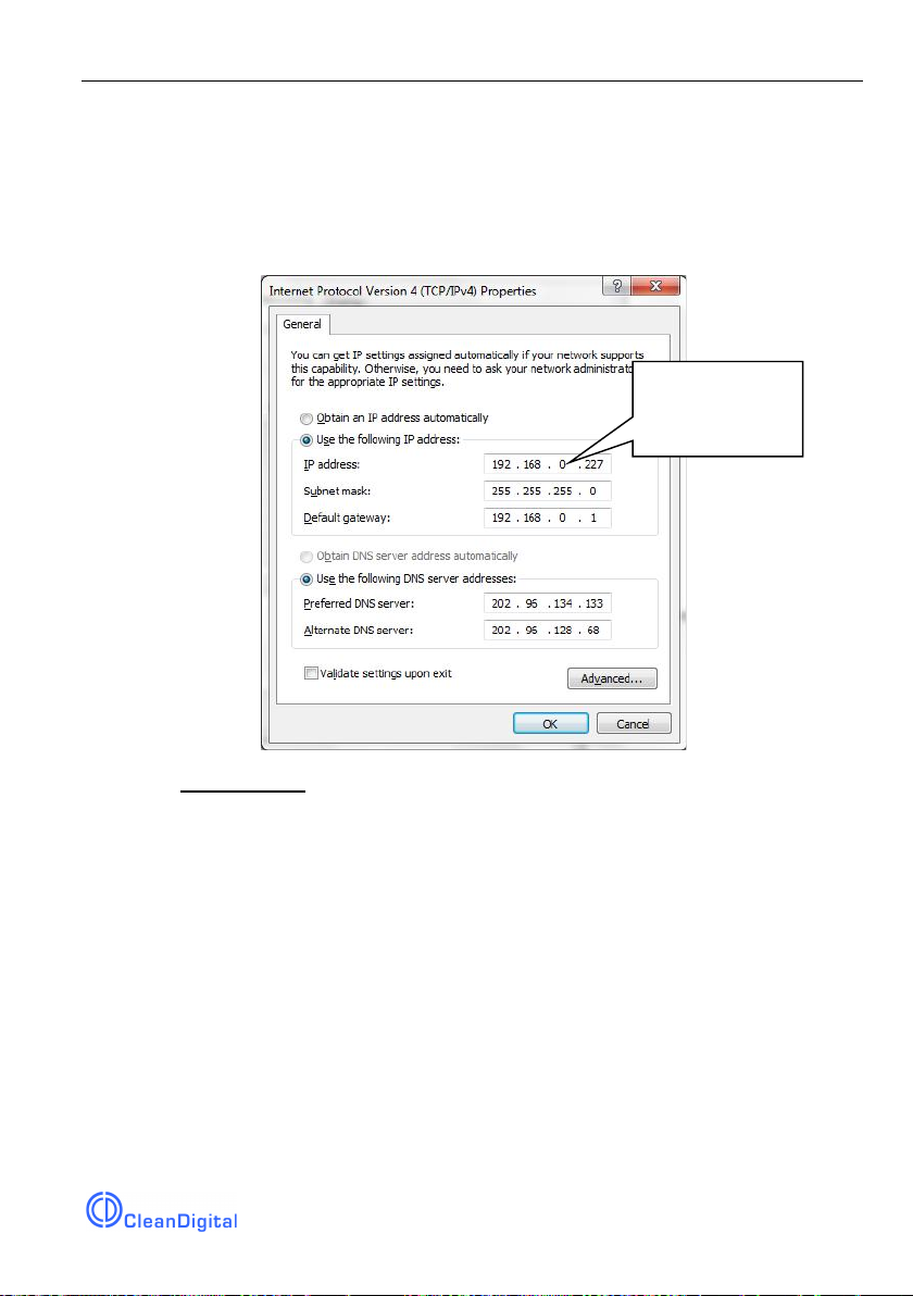
1. Connect a PC to the TCP/IP port on the rear panel, and set its network segment to
the same as the default IP of the product (192.168.0.178, port No.: 4001).
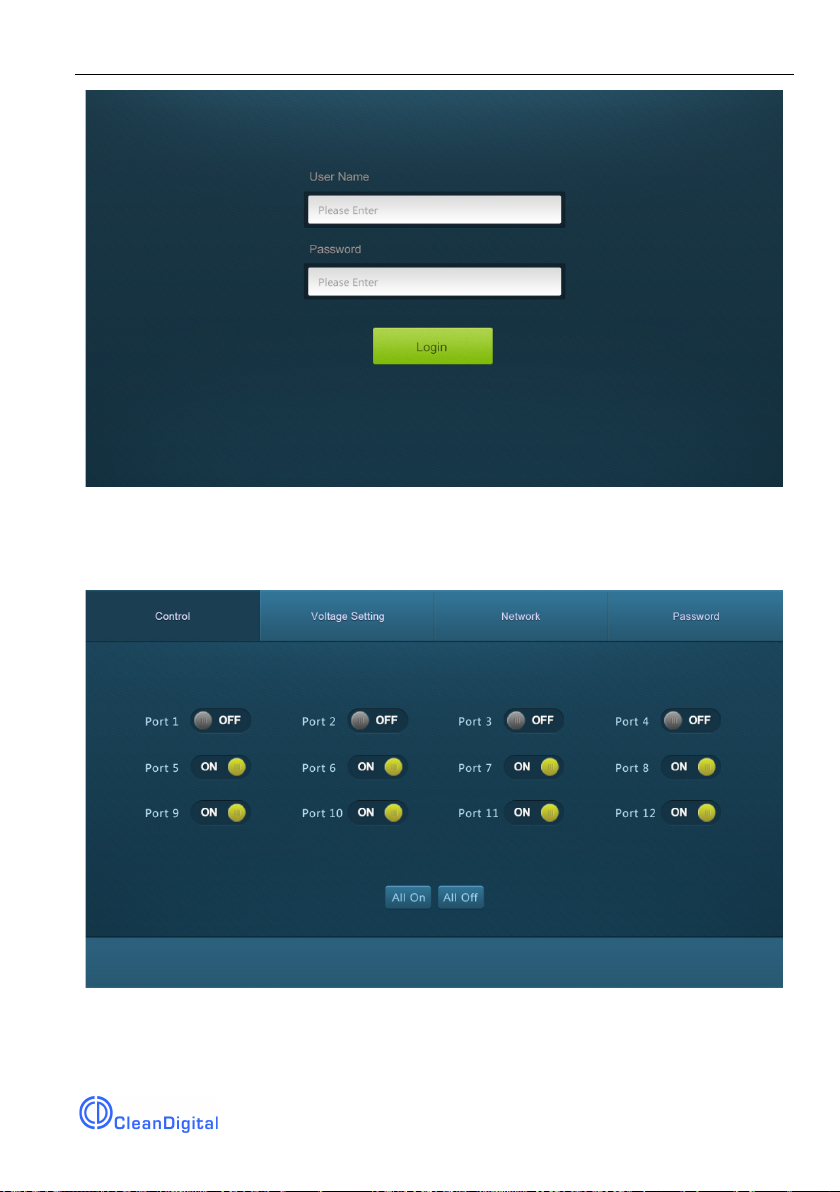
2. Type 192.168.0.178 in your browser, it will enter the log-in interface shown as
below:
Same network
segment as the
product.
Integrated Switching Power Supply
10
4.3.1 Control Menu
Type user name: user and password: user (default setting) on the log-in interface, and
then click Login to enter Control menu shown as below:
l Select the ON/OFF to switch on/off the output channel.
l Click the All On to switch on all output channels.
l Click the All Off to switch off all output channels.

Integrated Switching Power Supply
11
4.3.2 Voltage Setting Menu
Click Voltage Setting on the top of page to enter voltage setting menu shown as
below:
In this interface, you can select 5V, 12V, or 24V for each output channel.
4.3.3 Network Menu
Click Network on the top of page to enter network setting menu shown as below:

Integrated Switching Power Supply
12
In this interface, dynamic or static IP mode can be selected. Under static IP mode, IP
address and subnet mask, gateway can be set and make sure the IP addresses are
different to avoid IP conflict.
4.3.4 Password Menu
Click Password on the top of page to enter password menu shown as below:

Integrated Switching Power Supply
13
In this interface, the password can be modified as you need.
4.3.5 Web-based GUI Update
Web-based GUI for the Scaler Switcher supports online update in
http://192.168.0.178:100. Type the username and password (the same as the GUI log-
in settings, modified password will be available only after rebooting) to log in the
configuration interface. After that, click Administration at the source menu to get to
Upload Program as shown below:
Select the desired update file and press Apply, it will start upgrading then.

Integrated Switching Power Supply
14
5. Specification
Input & Output
Input Port
AC1 & AC2
Input Voltage
100~240VAC 50~60Hz
Output Port
Tota l 1 2 D C port (2-Pin phoenix connectors)
Output Voltage
5V, 12V or 24V can be selectable.
Output Voltage Range
5V: 4.75~5.25V
12V: 11.4~12.6V
24V: 22.8~25.2V
Maximum output power
consumption of signal channel
15W
Total output power consumption
180W
Control Part
Buttons Control
Front Panel: 01~12, total 12 buttons.
Rear Panel: Total 12 TACT Switches, named
SELECT.
RS232 Control
RS232 port (3-Pin phoenix connector).
Baud rate support 1200, 2400, 4800, 9600
(default), 19200, 38400, 57600,115200.
Web-based GUI Control
TCP/IP port (RJ45).
Default IP: 192.168.0.178
Port No.: 4001
General
Temperature
0 ~ +50℃
Humidity
10% ~ 90%
Dimension (W*H*D)
437mm x 44mm x 357mm
Net Weight
4.2Kg

Integrated Switching Power Supply
15
6. Panel Drawing
FIRMWARE
01 02 03 04 05 06
07 08 09 10 11 12
AC 2
AC 1
PSU12
AC100V 240V-
Tx Rx
RS232 TCP IP/
24V
+
AC100V 240V-
AC1 AC2
DC
12V
5V
+ ++ ++ ++ ++ ++ ++ ++ ++ ++ ++ ++
SELECT
24V
DC
12V
5V
SELECT
24V
DC
12V
5V
SELECT
24V
DC
12V
5V
SELECT
24V
DC
12V
5V
SELECT
24V
DC
12V
5V
SELECT
24V
DC
12V
5V
SELECT
24V
DC
12V
5V
SELECT
24V
DC
12V
5V
SELECT
24V
DC
12V
5V
SELECT
24V
DC
12V
5V
SELECT
24V
DC
12V
5V
SELECT
437 mm
44 mm

7. Troubleshooting & Maintenance
Problems
Causes
Solutions
No output voltage
Power supply protect function
will start when over loaded.
Please reduce loads.
After selecting output voltage,
the output channel will switch off
automatically.
Switch on the output
channel via front panel
button.
Fail or loose connection
Make sure the connection
is good.
AC1 or AC2 indicator
doesn’t work or no
respond to any
operation
Fail connection of power cord.
Make sure the power cord
connection is good.
Cannot control the
device by control
device (e.g. a PC)
through RS232 port
Wrong RS232 communication
parameters
Type in correct RS232
communication
parameters.
Fail or loose connection
Make sure the connection
is good.
Broken RS232 port
Send it to authorized
dealer for checking.
Cannot control the
device by front panel
buttons while can
control it through
RS232 port
The front panel buttons are
broken
Send it to authorized
dealer for repairing.
Cannot control the
device via Web-
based GUI
The IP address of control PC
and TCP/IP port are not on the
same network segment
Modify control PC’s
network segment to the
same with the TCP/IP port.
The port No. are wrong.
The correct port No. is
4001.
Fail or loose connection
Make sure the connection
is good.
Broken TCP/IP port
Send it to authorized
dealer for checking.
Cannot control the
device by RS232 /
front panel
The device has already been
broken.
Send it to authorized
dealer for repairing.
Table of contents
Popular Power Supply manuals by other brands

Daintree
Daintree GE Tetra GEPS24-300U-GLX2 installation guide

Keysight
Keysight E3630A Operating and service manual

Poppstar
Poppstar 1010214 Instructions for use

Puls
Puls FPT500.242-008-309 instruction manual

MAIMAN ELECTRONICS
MAIMAN ELECTRONICS MBL1500A user manual

Vimar
Vimar ELVOX 6837 INSTALLATION DIAGRAMS


