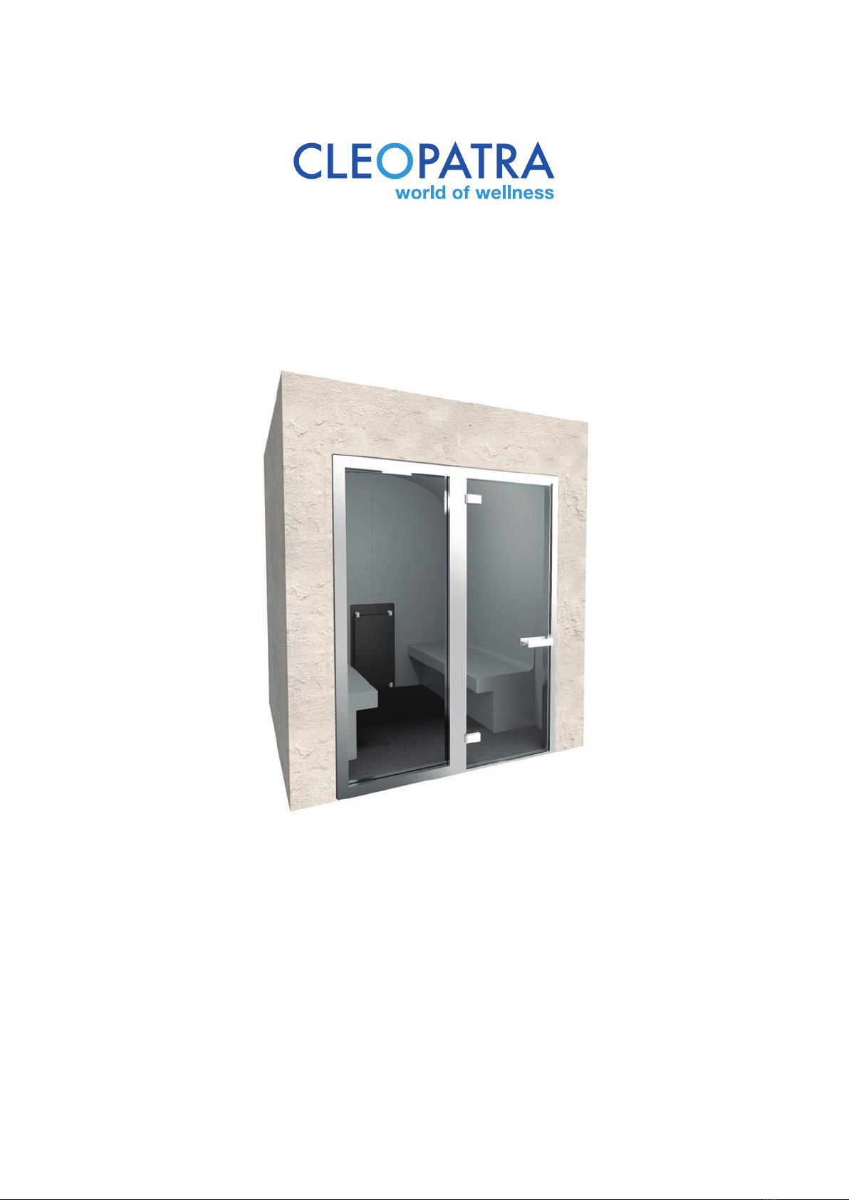
CLEOPATRA Vogue 1750 User manual

EN
Vogue cabins
1750/2000/2500
Installation manual
Item no: 90548810
EN2019/02 R01

2
Cleopatra B.V.
Oostzijde 295
1508 EN Zaandam
Netherlands
www.cleopatra.nl
www.cleopatra-wellness.com
Info@cleopatra.nl
Copyright
All information in this technical document, together with the drawings and technical specifications made
available by Cleopatra B.V., remain the property of Cleopatra B.V. and may not be copied without
permission. Cleopatra B.V. reserves the right to make changes in the interest of further developments.
Up to date on: 01- 01-2019

3
Table of contents
Installation manual
1 Introduction and safety............................................................................................................... 4
2 Warnings ............................................................................................................................... 5
3 Vogue 1750 ............................................................................................................................. 6
3.1 Scope of delivery .............................................................................................................. 6
3.2 Dimensions ....................................................................................................................... 7
4 Vogue 2000 ............................................................................................................................ 8
4.1 Scope of delivery .............................................................................................................. 8
4.2 Dimensions ....................................................................................................................... 9
5 Vogue 2500 .......................................................................................................................... 10
5.1 Scope of delivery ............................................................................................................ 10
5.2 Dimensions ..................................................................................................................... 11
6 Required tools and materials..................................................................................................... 12
6.1 Supplied tools ................................................................................................................. 12
7 Structure of the cabin...............................................................................................................13
8 Mounting the door module ....................................................................................................... 18
8.1 Mounting the door with frame ...........................................................................................19
8.2 Mounting the door with frame and window ........................................................................23
8.3 Mounting the door without frame....................................................................................... 30
8.3.a Mounting the door ...............................................................................................40
9 Mounting the steam inlet .......................................................................................................... 46

4
1 Introduction and safety
These instructions are intented for the installer. Read these instructions carefully to get to know the product, the parts
and the installation method. The Vogue cabin must be installed by qualified and well-trained personnel.
The Vogue cabin complies with the applicable standards and regulations and does not pose any direct danger for
the user if the Vogue cabin is installed according to the manufacturer’s instructions and is used in accordance with
this manual. The electronic and mechanical parts must be carefully maintained so that the Vogue cabin remains
fully operational. For this reason, the instructions must be followed closely.
All information and instructions in this manual have been compiled in accordance to the applicable standards and
regulations, the current technique and our years of experience and findings. National and local regulations must
be followed.
Check the product for possible transport damage. After the installation, a claim for (surface) damage will not be
accepted by Cleopatra.
Every right to warranty expires if adjustments have been made to the original product or parts. This manual must be
kept close to the product for quick access if needed.
The supplied plugs and screws are intended for building the Vogue cabin.
Cleopatra accepts no liability for damage caused by:
- Failure to follow the manual.
- Wrong use.
- Installation by unqualified personnel.
- Unauthorized changes to the product.
- Technical changes.
- The use of non-original spare parts.
Correct use:
- The Vogue cabin may only be used indoors.
- Use in another way is not permitted and is for the user’s own risk.
- Do not use the Vogue cabin when it is not in perfect condition.
- Do not use this product in an environment where it is exposed to corrosion.
Important instruction or description Pay attention: General danger

5
2 Warnings
Without permission and without instructions, the use of a steam cabin is
forbidden for the following persons:
- Children.
- Adults with disabilities.
- Persons who have not been instructed about what a steam cabin is
meant for.
- Persons who are intoxicated.
Bringing electrical devices in the cabin is forbidden!
Warning hot surfaces.
The steam inlet, the surrounding area and the steam itself are very hot. Do not touch them
because of danger of injuries.
Warning for slipping.
The floor of the cabin can be slippery.
Read the user manual carefully before using the steam cabin!
Maximum time to stay in the cabin: 15 min
Humidity in the cabin: max. 100%
Maximum temperature in the cabin: 45-48 ˚C

6
3 Vogue 1750
D: Coupling element
E: Vogue 1750 wall element
F: Front side wall right
I: Door 750 x 2050 (L/R)
J: Front side wall left
A: Vogue seat element square/wave
12503414
C
D
E
FJ
B
3.1 Scope of delivery
21053002/21053003
H GI
B: Back wall left
C: Back wall right
G: Adhesive tape
H: PVC coupling piece
A

7
3.2 Dimensions
D
(mm)
750
A
(mm)
B
(mm)
C
(mm)
1750 910 2300
Description
Vogue 1750 - 1 seat
750
1750 1660 2300Vogue 1750 - 2 seats
A
750
1750 2410 2300
Vogue 1750 - 3 seats
E
(mm)
2050
2050
2050
Pay attention! Dimensions are based on the standard
models “front with door”.
B
EC
D
C
B
D
(mm)
750
A
(mm)
B
(mm)
C
(mm)
1750 1330 2300
Description
Vogue 1750 - 1 seat
750
1750 2080 2300Vogue 1750 - 2 seats
A
750
1750 2830 2300
Vogue 1750 - 3 seats
E
(mm)
1900
1900
1900
Pay attention! Dimensions are based on the models
“frameless glass front” and “framed glass front”.
B
EC
D
C
B
EC
D1
D1
(mm)
660
660
660

8
4 Vogue 2000
C: Coupling element
D: Vogue seat element square/wave
E: Front side wall right
H: Door 750 x 2050 (L/R)
I: Front side wall left
12503414
B
C
D
EI
A
4.1 Scope of delivery
21053002/21053003
G FH
A: Back wall left
B: Back wall right
F: Adhesive tape
G: PVC coupling piece

9
D
(mm)
750
A
(mm)
B
(mm)
C
(mm)
2000 910 2300
Description
Vogue 2000 - 2 seats
750
2000 1660 2300Vogue 2000 - 4 seats
750
2000 2410 2300
Vogue 2000 - 6 seats
E
(mm)
2050
2050
2050
Pay attention! Dimensions are based on the standard
models “front with door”.
Pay attention! Dimensions are based on the models
“frameless glass front” and “framed glass front”.
750
2000 3160 2300Vogue 2000 - 8 seats
750
2000 3910 2300
Vogue 2000 - 10 seats
2050
2050
A
B
B
C
E
A
D
(mm)
750
A
(mm)
B
(mm)
C
(mm)
2000 1330 2300
Description
Vogue 2000 - 2 seats
750
2000 2080 2300Vogue 2000 - 4 seats
750
2000 2830 2300
Vogue 2000 - 6 seats
E
(mm)
1900
1900
1900
750
2000 3580 2300Vogue 2000 - 8 seats
750
2000 4330 2300
Vogue 2000 - 10 seats
1900
1900
A
B
B
C
E
A
D1
(mm)
660
660
660
660
660
C
E
DD1
4.2 Dimensions
D

10
5 Vogue 2500
D: Coupling element
E: Vogue seat element square/wave
F: Front side wall right
I: Door 750 x 2050 (L/R)
J: Front side wall left
B: Roof extender
12503414
C
D
E
FJ
A
5.1 Scope of delivery
21053002/21053003
H GI
A: Back wall left
C: Back wall right H: Adhesive tape
G: PVC coupling piece m1 door
B

11
5.2 Dimensions
D
(mm)
750
A
(mm)
B
(mm)
C
(mm)
2500 1660 2300
Description
Vogue 2500 - 4 seats
750
2500 2410 2300Vogue 2500 - 6 seats
750
2500 3160 2300
Vogue 2500 - 8 seats
E
(mm)
2050
2050
2050
Pay attention! Dimensions are based on the standard
models “front with door”.
Pay attention! Dimensions are based on the models
“frameless glass front” and “framed glass front”.
750
2500 3910 2300Vogue 2500 - 10 seats
750
2500 4660 2300
Vogue 2500 - 12 seats
2050
2050
A
B
B
C
E
A
D
(mm)
750
A
(mm)
B
(mm)
C
(mm)
2500 2080 2300
Description
Vogue 2500 - 4 seats
750
2500 2830 2300Vogue 2500 - 6 seats
750
2500 3580 2300
Vogue 2500 - 8 seats
E
(mm)
1900
1900
1900
750
2500 4330 2300Vogue 2500 - 10 seats
750
2500 5080 2300
Vogue 2500 - 12 seats
1900
1900
D1
(mm)
660
660
660
660
660
D
A
B
B
C
E
A
D
C
E
D1

12
6 Required tools and materials
3: Spirit level (min. 1m)
2: Ladder
4: Square
1: Screwdrivers (flat & cross)
5: Kit gun, use polymer sealant!
6: Screw, 4.5 x 60 mm
6.1 Supplied tools
90001082
3 4
1 2
5
6 7
7: Coupling plate
87
19800725
8: Corner anchor 19800720
9
9: Threaded rod plate
10: Sleeve M16
10 11 12 13
11: Nut M16
12: Ring M16
13: Threaded rod M16

13
7 Structure of the cabin
1
This construction method applies to the Vogue 1750, 2000 and the 2500.
Pay attention! You must level the floor yourself.
Place the back wall left and right against each other with the coupling elements.
polymer sealant
4.2 x 60
12 pc
90001082
2
640 mm
3
640 mm
Sleeve
Ring M16
Threaded
rod plate
Threaded rod M16, L: 120
mm
Threaded
rod plate
Ring M16
Nut
m16
Outside cabin

14
4.2 x 60
12 pc
90001082
5
640 mm
640 mm
4Place the seat element with the coupling element as the drawing below.
polymer sealant
Threaded rod plate
Sleeve
6
Threaded rod M16 (Length element)
Outside cabin

15
7Place the seat element with the coupling element as the drawing below.
polymer sealant
4.2 x 60
12 pc
90001082
8
640 mm
9
640 mm
Threaded rod plate
Sleeve
Threaded rod M16 (Length element)
Outside cabin

16
4.2 x 60
12 pc
90001082
640 mm
640 mm
Place the seat element with the coupling element as the drawing below.
polymer sealant
Threaded rod plate
Sleeve
10
11 12
Threaded rod M16 (Length element)
Outside cabin

17
Place the seat element with the coupling element as the drawing below.
polymer sealant
4.2 x 60
12 pc
90001082
640 mm
640 mm
Threaded rod plate
Sleeve
13
14 15
Threaded rod M16 (Lengte element)
Outside cabin

18
Choose the door that applies to you and follow the instructions.
1See paragraph 9.1
3
8 Mounting the door module
See paragraph 9.3
2See paragraph 9.2
Door with frame Door with frame and window
Door without frame

19
4.2 x 60
12 pc
90001082
640 mm
640 mm
Place the front wall left with the coupling element as shown in the
drawing below.
polymer sealant
Threaded rod plate
Threaded rod M16 L: 120 mm
Nut M16
Ring M16
8.1 Mounting the door with frame
1
23
Outside cabin

20
4.2 x 60
12 pc
90001082
640 mm
640 mm
Place the front wall right with the coupling element as shown in the
drawing below.
polymer sealant
Threaded rod plate
Threaded rod M16 L: 120 mm
Nut M16
Ring M16
4
56
Outside cabin
This manual suits for next models
2
Table of contents
Popular Plumbing Product manuals by other brands

BELLOSTA
BELLOSTA movida 5605/6/E installation instructions

Dyconn
Dyconn Coronado TB001-A03CHR manual

Kohler
Kohler K-3444K-NS Installation and care guide

Lefroy Brooks
Lefroy Brooks M1-4701 Installation, operating, & maintenance instructions

Lefroy Brooks
Lefroy Brooks M1-4101 Installation, operating, & maintenance instructions

Helvex
Helvex 110-WC-4.8 installation guide

Elkay
Elkay Elite Gourmet 3626EGDF Specifications

Helvex
Helvex 185-19 installation guide

Moen
Moen Show House S415 Series manual

Spectrum Brands
Spectrum Brands Pfister Contempra LG42-N Quick installation guide

ZUCCHETTI
ZUCCHETTI Helm ZHL516 Instruction for the installation

Grohe
Grohe GROHTHERM XL 35 085 manual