Cleveland Motion Controls Cleveland-Kidder TMI User manual

INSTRUCTION mm. A800-7425 J (Page 1 of 16)
1.0 GENERAL INFORMATION
1.1 RECEIVING AND UNPACKING
Handle and unpack the equipment carefully.Operating Conditions
Immediatelyuponarrival,check theshipment against the
packing list. Any damage should be reported
immediately to the carrier and to the nearest CMC
representative.
Equipmentwhich willnot be installedimmediately should
be stored in a clean, dry location. Precautions should be
taken to prevent moisture, dust and dirt from
accumulating in storage and installation areas.
1.2 SPECIFICATIONS
Electrical
AC Supply -100/115/230VAC ±10%,
50/60Hz, Jumper selectable
Input Power -15 VA
Transducer
Excitation -5.6 VDC
Tension
Output Signal -0-10 VDC, 5 mA
Conditioned -0-10 VDC, 5 mA or adjustable
Tension Output 0-2 VDC, approximately 2K
Signal Ohm output impedance
Calibration -Full scale range of 8:1
TLD Output -1 N.O. & 1 N.C. 5 Amp,
Contactor 250 VAC resistive (each limit)
(Optional)
Isolation -0-10 VDC, 5 mA or 4 to
Amplifier 20 mADC, 1500 VRMS
(Optional) (2000V peak) isolated
Ambient
Temperature -0-40EC (32-104EF)
Relative
Humidity -5%to 95% (w/ocondensation)
Altitude -to 6600 Ft. (2000 meters)
Weight
Enclosed Indicators -12 Lbs.
Open Panel
Indicators -3 Lbs.
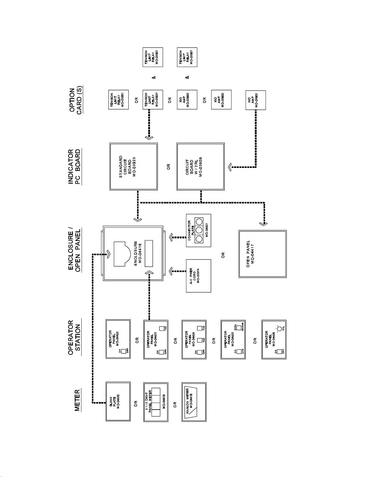
1.3 DESCRIPTION
The indicators are assembled from modules as shown in
Figure 1 on page 2. The modular approach improves
versatility by increasing the combinations of features
available.
1.3.1 Circuit Boards - There are two circuit boards
available. - Standard Circuit Board
- TRL Circuit Board
The Standard circuit board amplifiesthe signals from the
transducer(s) and provides a tension output signal which
represents the total tension measured by the
transducers.
TheTRL circuit board independently amplifies the
signalsfrom each oftwo transducers, theleft transducer
andthe right transducer of the sensing roll. There are
three tension output signals from this circuit board, one
for the left transducer, one for the right transducer, and
one for the total of the left and the right.
2 of 18 A800-7425 J
Figure 1
1.0 GENERAL INFORMATION

3 of 18 A800-7425 J
1.0 GENERAL INFORMATION
1.3.2 Operator Panels - There is a selection of fivewiringharnessextensionareused.Shieldedwire should
operator panels which have the following switches. be used as shown on the installation wiring diagram.
- ON/OFF 1.3.6 Connector Plate Option - The connector plate has
- ON/OFF + TLD two 5 pin receptacles for transducer cables and a 3 pin
- ON/OFF + TLD + TLD receptacle for the tension output signal. It includes a
- ON/OFF + DUAL RANGE wiring harness for connections to the circuit board, and
- ON/OFF + TRL mounts on the bottom of the enclosure.
The operator panels consist of the nameplate, switches 1.3.7 AC Power Card (115 VAC only) Option - This
and attached wiring harness. option includes a 115 VAC line cord and bushing. It
The ON/OFF switch controls the line power
The TLD switch enables or disables the tension limit
relay card.
The dual range switch increases the analog meter
sensitivity by 4 times. It cannot be used with a digital
meter.
The TRL switch changes the meter display to left, total
orright transducer tension(requires TRL circuit board).
1.3.3 Output Card Option - There are two plug-in
output option cards available.
- Tension Limit Detection Relay Card
- Isolation Amplifier Card
Up to two output option cards can be used per indicator
except that only one isolation amplifier card can be used
per indicator.
The TENSION LIMIT DETECTION RELAY card
can be used for low or high tension limit detection. The
ISOLATION AMPLIFIER card provides an isolated
0-10 VDC or a 40-20mADC output.
1.3.4 Digital/AnalogMeter/BlankPlateOption -A 3½
inch digit panel meter or a 5½ inch analog meter are
available. The blank meter plate can be installed if the
meter is not mounted to the enclosure.
1.3.5 Enclosure/Open Panel - The enclosure is used for
wall mounting and the open panel is used for mounting
insidea console. The meters, operator panels and
connector plate can be used with the open panel
provided that a customer supplied terminal block and
mounts in the bottom of the enclosure.
1.4 EQUIPMENT DESCRIPTION
Refer to Figure 2 on page 4.
1. Terminal Block (2TB) - This terminal block has a
moveable jumper for selecting the proper line
voltage.
2. ZeroPot (1P) - This adjustment is used to
electronically zero out the tare weight of the
tension sensing roll during installation and
calibration. On TRL versions, it calibrates the left
transducer only.
3. Calibrate Pot (2P) - This adjustment is used to
calibrate the full scale tension reading. For
example, a 0-100 scale might be calibrated 1:1 to
read 100# full scale, or perhaps 2:1 to read 50# full
scale. On TRL versions, it calibrates the left
transducer only.
4. RightZero Pot -(3P) - This adjustment is installed
for TRL versions only. It is used to calibrate the
right transducer only.
5. Right Calibrate Pot (4P) - This adjustment is
installed for TRL versions only. It is used to
calibrate the right transducer only.
6. TLD Select Switch (SW) - For TLD (Tension
Limit Detection Relay) option only. For low limit
detection set switch to L position. For high limit
detection set switch to H position.
7. Tension Limit Detector Delay Pot - For TLD
option only. It determines the time delay between
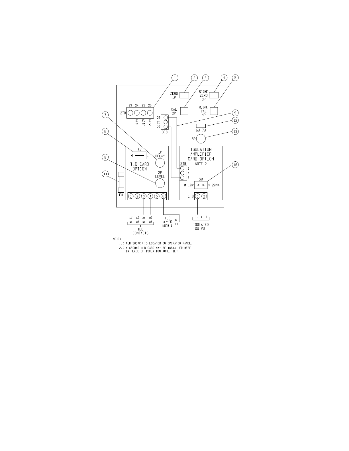
4 of 18 A800-7425 J
Figure 2
when the tension level goes out of range and the
switching of the TLD relay.
1.0 GENERAL INFORMATION
8. Tension Limit Detector Level Pot - For TLD12. Jumper - This moveable jumper should be in
option only. This adjustment sets the tension levelposition 7J for use with digital tension meter.
at which the TLD relay switches. Position 6J provides a 0-10VDC tension signal
9. Isolation Amplifier Power Cable - For isolation
amplifieroption only.The cable must be connected13. Potentiometer 5P - Adjustment for the digital
between 22TB on the isolation amplifier and 3TBtension meter display.
on the indicator main circuit board. It supplies
power to operate the isolation amplifier.
10. IsolationAmplifier Selection Switch - For isolation
amplifier option only. Set switch to 0-10V position
for 0 to 10 VDC output, set switch to 4-20mA
position for 4-20mADC output.
11. Line Power Fuse - Replace with 3AG, 0.5A, 250
fuse only.
output.
1.5 PRINCIPLES OF OPERATION
The measurement of the actual tension in a web is made
by sensing, with strain gage transducers, the force on a
sensing roll caused by the tension in the web. The
electrical signal from the transducers is registered on the
tension indicator meter as the total tension.

5 of 18 A800-7425 J
Figure 3
WARNING
These Installation Instructions are for use by
qualifiedpersonnel only. Toreduce the risk of
electric shock, do not perform any servicing
other than that contained in the Operating
Instructions unless you are qualified to do so.
CAUTION
Before making any line power connections,
verifythat the 100/115/230V jumper at2TB on
theCircuit Board Assembly is set for the
proper voltage. Refer to the following table:
The indication system shown in Figure 3 utilizes two
strain gate transducers and sums the signals in the indicator.
The Tensi-Master indicators can also be used for
cantilever, wire, and single transducer applications.
1.0 GENERAL INFORMATION
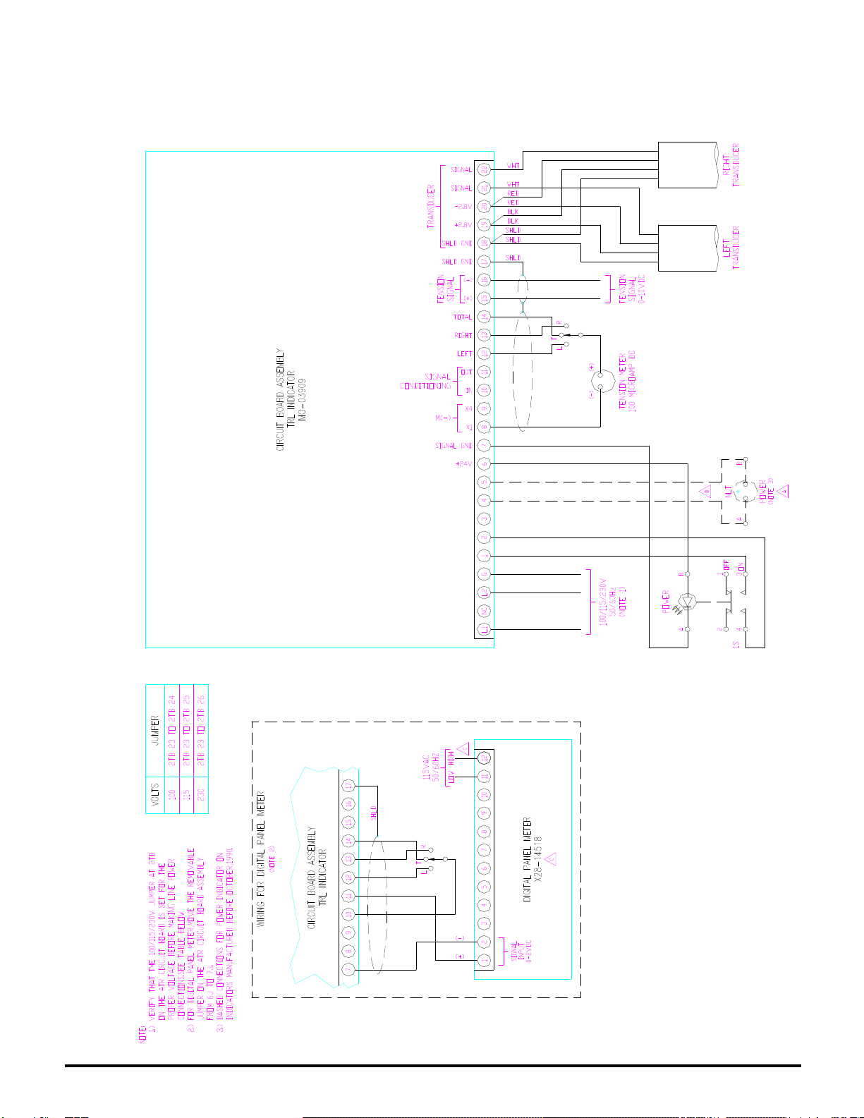
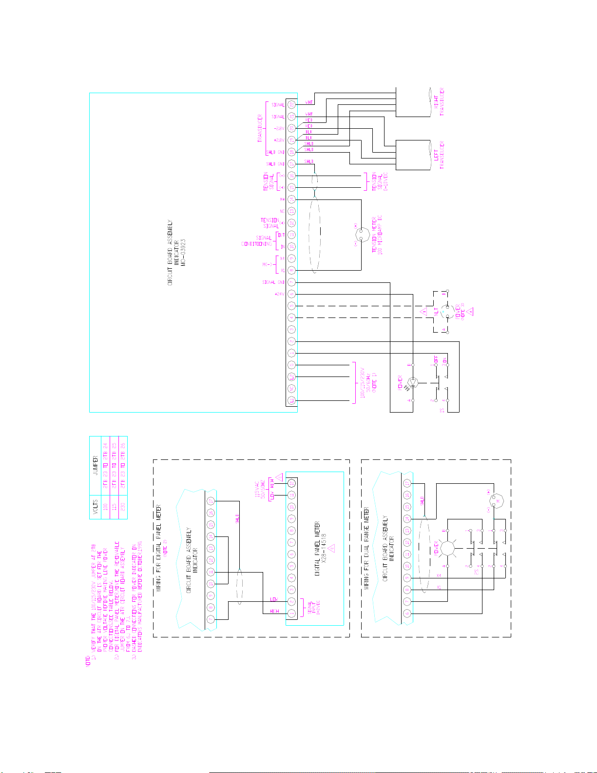
2.0 INSTALLATION
AC VOLTS JUMPER
100 2TB-23 TO 2TB-24
115 2TB-23 TO 2TB-25
230 2TB-23 TO 2TB-26
Look in the back of the manual for the outline drawing
for mounting dimensions and the wiring diagram for
cable connections.
For indicators with terminal block connections, the ends
of the transducer cables having the shield lead are
connected to the indicator. For indicators which have
MSconnectors, the ends of the transducer cables that
are marked white are connected to the indicator. For
indicator mating connectors, refer to the following table.
MATING CONNECTORS FOR INDICATORS

Position
on wire
Squeeze
pliers
Push into
hole
AC POWER CORD HOOKUP
6 of 18 A800-7425 J
Figure 4
USE CMC P/N DESCRIPTION
Transducer X43-06825 5 Pin Connector
Cable MS-3106A-14S-5P
X43-06928 Clamp and Bushing
Amphenol 97-3057-1007-1
Tension X43-07181 3 Pin Connector
Output MS-3106A-14S-7P
Signal X43-06928 Clamp and Bushing
Amphenol 97-3057-1007-1
2.0 INSTALLATION
2.1 AC POWER CORD HOOKUP (MO-03074)
Positionthe strain relief bushing on the line cord as
shown. Insert the line cord into the rectangular hole in
the bottom of the enclosure. Refer to Figure 4.
Makethe following connections to terminal block 1TB.
Brown wire to L1
Blue wire to L2
Green wire to G
Using pliers, squeeze the mating halves of the strain
relief bushing together and insert intothe enclosure hole.
2.2 TENSION LIMIT DETECTION
RELAY OPTION
If the output contacts are to be used (See Section 3.4),
aconduit hole must be drilled in the enclosure bottom in
orderto bring the output contacts external to the tension
indicator.
Use ½ inch electrical trade size conduit. Refer to the
National Electric Code for guidelines governing
installation and wiring.

1 .7MOUNTING LOCATION, TLD OUTPUT CONTACTS
SIZE HOLE FOR 1/2 INCH ELECTRICAL CONDUIT
1 /2"
AC POWER
CORD
7 of 18 A800-7425 J
Figure 5
WARNING
The following Calibration Instructions are for
useby qualified personnelonly. To reduce the
risk of electric shock, DO NOT perform any
servicing other than that contained in the
Operating Instructions unless you are qualified
to do so.
Route the required output contact wiring from the
Tension Limit Detection Relay Card terminal block
through this conduit. See Figure 5.
3.0 ADJUSTMENTS
Check that the indicator has been wired correctly per
the installation wiring diagram and that the jumper at
2TB is set for the proper line voltage.
3.1 ANALOG METER MECHANICAL
ZERO-ADJUSTMENT
Before turning the unit on, check to see that the meter
needle is on zero. Make any required adjustments with
the small zero adjustment screw on the meter face.
3.2 ELECTRICAL ZERO-ADJUSTMENT
Switch the unit on and allow three or four minutes
warm-up time. The pilot light will indicate power is being
supplied to the indicator.
The models with the TRL feature have a zero and a
calibrate adjustment for both the left transducer and

8 of 18 A800-7425 J
Figure 6
3.0 ADJUSTMENTS
the right transducer. Calibrate the left transducer with be suitable to calibrate using a 100 lb. weight (or
the TRL switch in the left position and calibratethe right100 lbs. force on a spring scale).
transducer with the TRL switch in the right position.
Witha screwdriver, turn the calibrate adjustmentmeter needle to the desired reading.
potentiometer ¾ clockwise. Using the zero adjustment
potentiometer, zero the tension meter. D. Remove the load. The meter should return to zero.
Check to see that the system is operating properly byand C again checking meter zero. Two or three
applying a force to the sensing roll. Pushing or pulling inload applications are sometimes required to
the load direction of the web force should cause theproperly "seat" the transducers. With all
tension meter to move up scale. adjustments completed, remove any cords and
3.3 CALIBRATION
The unit should be calibrated so that normal running
tensions will be about mid-scale and the maximum
tensions will not go off scale.
For TRL models, calibrate each transducer for about
25% of scale so that the total signal is about mid-scale.
NOTE: It is recommended that the indicators be
calibrated with the transducers at the process operating
temperature.
Spring Scale or Weight Method of Calibration
A. Thread a length of rope or flat webbing over the
center of the sensing roll, as shown in Figure 6. Do
notthread over non-turningrollers, driven rolls, or
frame braces as any sliding friction will cause
inaccurate calibration.
B. Apply a known tension load using weights or a
spring scale. If possible, the applied load should be
approximately the same as the anticipated
operating tension. If, for example, a normal
operating tension of 100lbs is anticipated, it would
C. Usingthe CALIBRATE adjustment bring the
If necessary, readjust ZERO then repeat steps B
weights used in the calibration procedure.
If it is found during running that the operating tension is
much less (or greater) than estimated, a recalibration
may be required.
3.3.1 Calibration with Dual Range (Scale X4) Feature
-The calibration procedure is similar to that for standard
indicators except that the calibration should be made on
the most sensitive scale (lower scale). For example, with
0-25/0-100 meter scale, calibrate on the 0-25 scale.
3.3.2 Calibration with TRL Feature - The calibration
procedure issimilar to thatfor standard indicators. Note
that the calibration procedure can be made in either of
two ways. The quickest method is to apply a known
tension load exactly midway between the transducers.
Then calibrate on each side for ½ of the load. That is,
with the indicator on TOTAL apply a known load for
example, 50 Lbs. Switch to RIGHT and calibrateso the
meter reads 25 Lbs. Switch to LEFTand again calibrate
to 25 Lbs. If necessary, repeat the calibration.
Calibration can also be made by applying loads
simultaneouslytobothtransducers.TheTOTALshould
always be equal to the sum of the two applied loads.
3.4 CALIBRATION OF THE TLD CARD
OPTION
If the TLD card is not installed, mount it with the four
plastic standoffs to the indicator circuit board assembly
as shown in Figure 2. Connect a TLD on-off switch as
shown in Figure 2.

9 of 18 A800-7425 J
3.0 ADJUSTMENTS
3.4.1 TLD Low Limit Calibration - Put TLD select
switch to L position. In order for the TLD circuit to
operate, the TLD switch on the front cover must be on
(illuminated). If the switch is off the TLD function is
bypassed.
The tension limit detector level (2P) on the TLD card
shouldbeadjustedslightlybelowtheminimumoperating
tension. The tension limit detector delay (1P) on the
TLD card should be adjusted for the minimum time
delay without causing the TLD relay to trip on normal
tension transients.
Whenthe tension dropsbelow the tension limit detector
level set point, a set of normally open and normally
closed relay contacts on the TLD card will switch
states.
3.4.2 TLD High Limit Calibration - Put TLD select
switch to H position. In order for the TLD circuit to
operate, the TLD switch on the front cover must be on
(illuminated). If the switch is off the TLD function is
bypassed.
The tension limit detector level (2P) on the TLD card
should be adjusted slightly above the maximum operating
tension. The tension limit detector delay (1P) on the
TLD card should be adjusted for the minimum time
delay without causing the TLD relay to trip on normal
tension transients.
When the tension rises above the tension limit detector
level set point, a set of normally open and normally
closed relay contacts on the TLD card will switch
states.
3.5 ISOLATION AMPLIFIER OPTION
Mount the isolation amplifier card to the indicator circuit
board with the four plastic standoffs as shown in Figure
2. Connect the short 3 wire cable from 2TB on the
isolation amplifier card to 3TB on the indicator circuit
board.
Positionthe switch on the isolation amplifier card to the
0-10V position fora 0 to 10 VDC isolated tension output
signal, or to the 4-20mA position for a 4-20mADC
isolated tension output signal. 3.6.1 Decimal Point Selection
3.6 DIGITAL TENSION METER
Asignal conditioning circuit is included on the indicator
circuitboard for displayingthe tension on a digital meter.
The moveable jumper on the circuit board should be in
position 7J.
When the 0-10 VDC tension output signal is fed to 1TB-
10 on the circuit board a conditioned adjustable 0 to 2
VDC for the digital meter is present at 1TB-11.
Potentiometer 5P of the signal conditioning circuit
normally is factory adjusted for a 0-1 VDC output with
a0-10 VDC tension output signal as an input. This
allows a 3½ digit 0-2 VDC digital meter to display 100.0
at full scale.
By adjusting 5P, the full scale reading on the 2 VDC
digital panel meter can be changed to any reading
between 35.0 to 199.9 with a 10 VDC tension output
signal present at 1TB-10.

10 of 18 A800-7425 J
WARNING
These TroubleshootingInstructions are for use
by qualified personnel only.To reduce the risk
of electric shock, donot perform any servicing
other than that contained in the Operating
Instructions unless you are qualified to do so.
4.0 TROUBLESHOOTING
4.1 EXCESSIVE OUTPUT SIGNAL
WITH NO LOAD
Try to re-zero with zeroing pot(s).
There may be a high degree of misalignment of the
transducers causing a severe pre-load.
or
The sensing guide roll assembly may be excessively
heavy. The sensing guide roll should not weigh more
than ½ the maximum working force of the transducers
in most cases.
4.2 LOW OUTPUT SIGNAL
The transducer may have too large a maximum working
forcefor the application. Replace with a lower
maximum working force transducer or increase web
wrap angle.
4.3 OUTPUT SIGNAL FAILS TO INCREASE
WITH ADDED LOAD
The transducers are overloaded and are hitting their
stops. Replace the transducers with ones having a
higher maximum working force or reduce the load. This
may be accomplished by reducing the web wrap angle
and/or using a lighter sensing roll.
4.4 WRONG POLARITY OF OUTPUT
SIGNAL
Transducersmayhavebeenincorrectlyoriented.Rotate
transducers 180 degrees or if rotation is impossible,
interchangethe redand theblack transducer cableleads
at the tension indicator.

11 of 18 A800-7425 J
4.5 OUTPUT SIGNAL NOT LINEAR, OR
ZERO SHIFTS DURING OPERATION
Check transducer and tension roll mounting. All
mountingbolts must be tight. Check that there is no dirt
or foreign matter interfering with the transducer
mounting.
4.6 NO OUTPUT SIGNAL
Check to see that all connections have been made
completely. Check for places where the connecting
cables might be crimped or cut. Verify that AC
Voltage is present from 1TB-3 to 1TB-4.
4.7 VERY HIGH OUTPUT WITH NO LOAD
Check cables and connectors for good connections and
check continuity of cables with an ohmmeter. Check for
proper wiring to transducers.
Check transducer gage resistance as given in the
transducer instruction manual.
5.0 REPLACEMENT PARTS
Description Use P/N
Lamp Power ON/OFF X01-21443
Switch, PB Power ON/OFF X16-11705
Lens, Red Power ON/OFF X01-21442
Lamp, 28V TLD X01-11702
Switch, PB TLD X16-11705
Lens, Orange TLD X16-13943
Lamp, 28V Dual Range X01-11702
Switch, PB Dual Range X16-11739
Lens, Orange Dual Range X16-13943
Switch, 3 Position TRL X16-09930
Knob TRL X01-13944
Fuse, 250V, .25A Circuit Board X21-07231
6.0 SERVICE ASSISTANCE AND
REPAIR
For additional service assistance, please obtain the
Type, MWF, and Serial Number from the nameplate.
Contact the Factory Service Department.
Phone: (216) 524-8800
Fax: (216) 642-5155
Disassembly byimproperly trained personnel may result
in additional damage to these units. Should repairs be
required or for warranty repairs, contact the Customer
Service Department for a return authorization number
before returning the units.
12 of 18 A800-7425 J
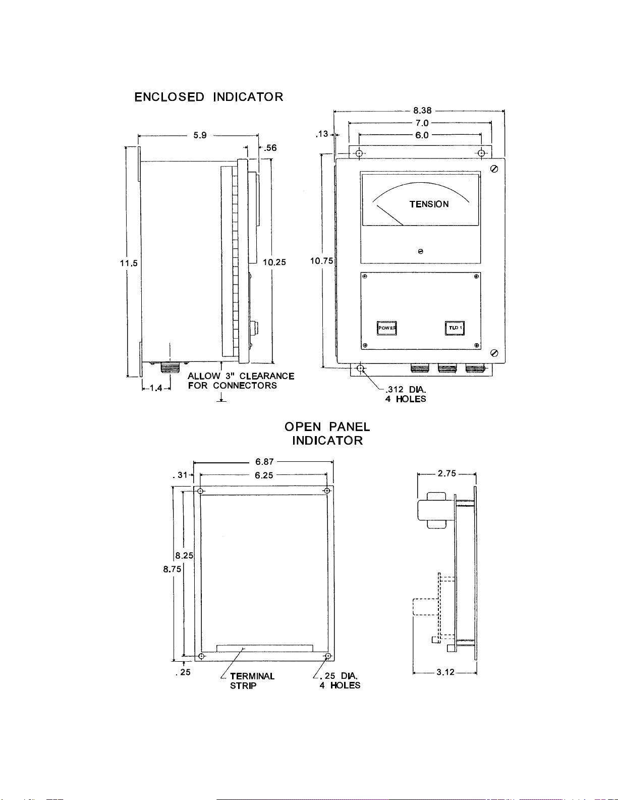
7.0 OUTLINE DIMENSIONS
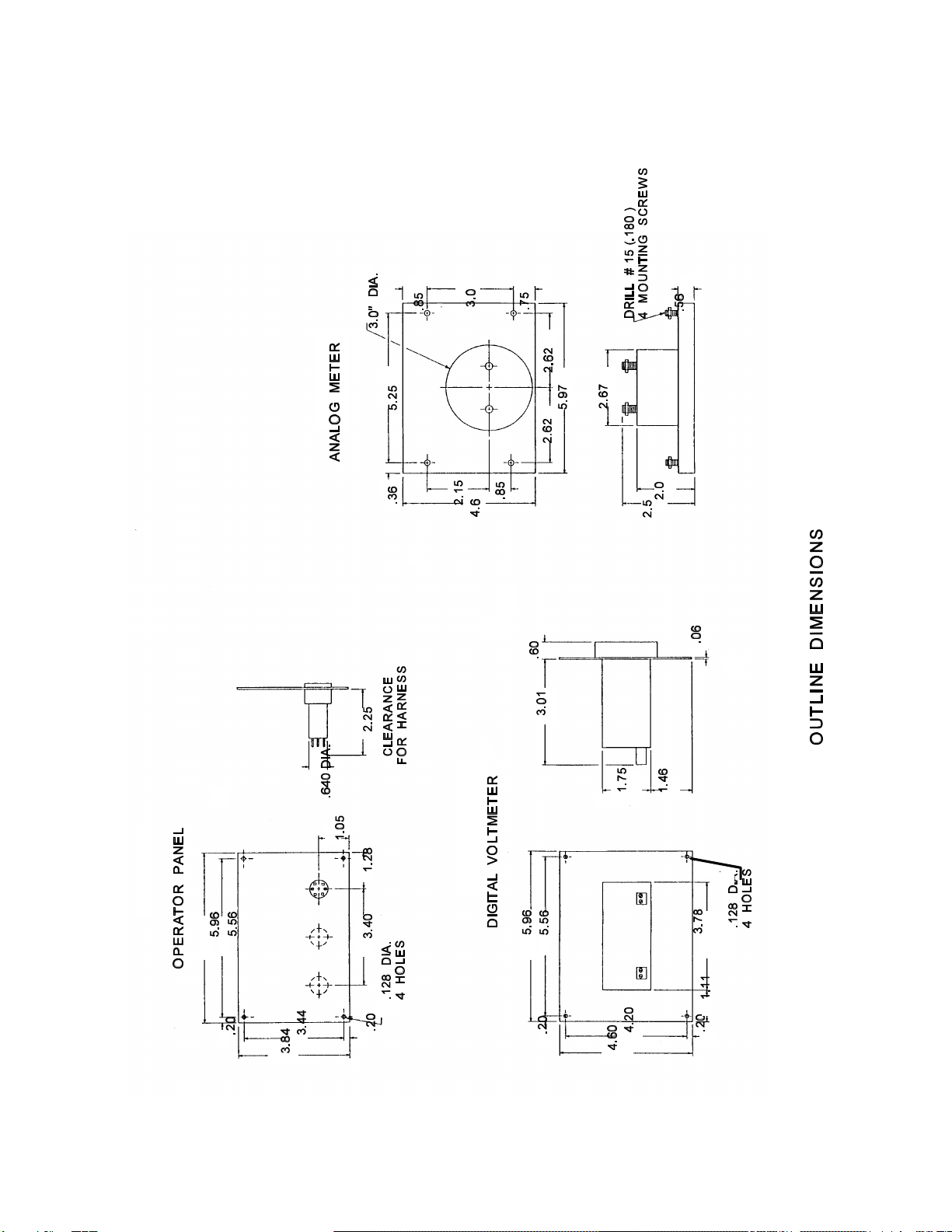
13 of 18 A800-7425 J
7.0 OUTLINE DIMENSIONS

3 RECP2 RECP1 RECP
123 4 5 6
15 16 17 18 19 20 21 22
SIGNAL
TRANSDUCER
ABC D E A B C D E A B C
TENSION
D
LEFT RIGHT
TRANSDUCER TRANSDUCER TENSION
SIGNAL
0 - 10 VDC
1234 5 6
T L D
NOTE: T L D TERMINALS 1 & 2 NORMALLY CLOSED AND
3 & 4 NORMALLY OPEN WHEN TENSION IS
WITHIN THE NORMAL OPERATING LIMITS.
EACH CONTACT IS RATED AT 5 AMP , 115 VAC RESISTIVE.
12 3 4 5 6 7 8 9 10 11
T L D CARD
T L D
A B
2
4 3
1OFF
ON
CIRCUIT BOARD ASSEMBLY
T L D CARD
CIRCUIT BOARD ASSEMBLY
SCHEMATIC, TLD OPTION
INSTALLATION
WIRING DIAGRAM
FOR TLD CARD SCHEMATIC
CONNECTOR PLATE
14 of 18 A800-7425 J
8.0 INSTALLATION WIRING DIAGRAM
15 of 18 A800-7425 J
INSTRUCTION mm. A800-7425 J (Page 1 of 16)
8.0 INSTALLATION WIRING DIAGRAM
16 of 18 A800-7425 J
8.0 INSTALLATION WIRING DIAGRAM

17 of 18 A800-7425 J
9.0 WARRANTY AND LIMITATION OF LIABILITY
CLEVELAND MOTION CONTROLS, INC.
LIMITED WARRANTY.
ALLGOODS ARE SOLD SUBJECT TO
THE MUTUAL AGREEMENT THAT
THEY ARE WARRANTED BY THE
COMPANY TO BE FREE FROM
DEFECTS IN MATERIAL AND
WORKMANSHIP FOR ONE YEAR
FROM THE DATE OF SHIPMENT. THE
COMPANY'S WARRANTY DOES NOT
COVER, AND IT MAKES NO
WARRANTY WITH RESPECT TO ANY
DEFECT, FAILURE, DEFICIENCY OR
ERROR WHICH IS:
A) NOTREPORTED TO THE
COMPANY WITHIN THE
APPLICABLE WARRANTY
PERIOD; OR
B) DUE TO MISAPPLICATION,
MODIFICATION,
DISASSEMBLY, ABUSE,
MISUSE, IMPROPER
INSTALLATION,
UNAUTHORIZED REPAIR,
IMPROPER MAINTENANCE OR
ABNORMAL CONDITIONS OF
TEMPERATURE, DIRT OR
CORROSIVE MATTER; OR
C) DUETO OPERATION, EITHER
INTENTIONALOR
OTHERWISE, ABOVE RATED
CAPACITIES OR IN AN
OTHERWISE IMPROPER
MANNER.
THE FOREGOING WARRANTY IS IN
LIEUOF ALL OTHER WARRANTIES.
THE PARTIES AGREE THAT THE
IMPLIED WARRANTIES OF
MERCHANTABILITY AND FITNESS
FORA PARTICULAR PURPOSE AND
ALL OTHER WARRANTIES, EXPRESS
OR IMPLIED, ARE EXCLUDED FROM
THE
SAL
E
OF GOODS.

18 of 18 A800-7425 J
INSTRUCTION mm. A800-7425 J (Page 1 of 16)
LIMITATION OF REMEDY AND
LIABILITY.
THE REMEDY PROVIDED HEREIN IS
BUYER'S SOLE AND EXCLUSIVE
REMEDY. THE BUYER'S REMEDY
AND THE COMPANY'S LIABILITY
(WHETHER UNDER THE THEORIES
OF BREACH OF WARRANTY,
CONTRACT, TORT INCLUDING
NEGLIGENCE OR STRICT LIABILITY
OR ANY OTHER LEGAL THEORY)
SHALL BE LIMITED EXCLUSIVELY
AT THE COMPANY'S OPTION TO
REPLACING OR REPAIRING
WITHOUT CHARGE AT THE
COMPANY'S FACTORY OR
ELSEWHERE ANY MATERIAL OR
WORKMANSHIP DEFECTS WHICH
BECOME APPARENT WITHIN ONE
YEAR FROM THE DATE ON WHICH
THEGOODS WERE SHIPPED. THE
COMPANY SHALL NOT BE LIABLE
FOR SPECIAL, INCIDENTAL OR
CONSEQUENTIALDAMAGES OF ANY
KIND INCLUDING BUT NOT LIMITED
TO DAMAGES FOR LOSS OF USE,
INCOME OR PROFIT, OR LOSSES
SUSTAINED AS A RESULT OF INJURY
(INCLUDING DEATH) TO ANY
PERSON OR DAMAGES TO
PROPERTY. THE COMPANY SHALL
HAVE NO LIABILITY FOR DAMAGES
OF ANY KIND ARISING FROM THE
INSTALLATION AND/OR USE OF THE
GOODS BY ANYONE. BY THE
ACCEPTANCE OF THE GOODS, THE
BUYER SHALL ASSUME ALL
LIABILITY FOR ANY DAMAGES
WHICH MAY RESULT FROM USE OR
MISUSE BY THE BUYER, ITS
EMPLOYEES OR BY OTHERS.
Table of contents


