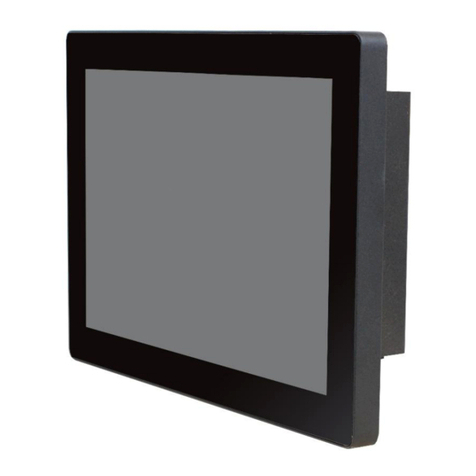
Autobase ATP15 User manual

Just Touch
autobaseTouch
Intelligent
Touch Panel
Computer
ATP15/15P/17/19
User Manual
http://www.autobase.biz
1201, Biz Center, SKnTechno Park, Sangdaewon-dong,
Jungwon-gu, Seongnam-si, Gyeonggi-do, Korea
Phone : +82.31.776.0800 / Fax : +82.31.776.0802
http://www.autobase.biz

autobaseTouch
ATP15 / ATP17 / ATP19

This user manual and all about copyright of Autobase ATP series panel computer
© Autobase, Inc. All rights reserved
< Notice >
Information in this document is subject to change without prior notice.
Printed, November 26, 2012

Contents
1. ATP Configurations··························································5
1.1 ATP Hardware Specifications ············································ 5
1.2 Part Names and Description·············································· 6
1.3 ATP15 Dimensions and Panel Cut-out································· 7
1.4 ATP15P Dimensions and Panel Cut-out······························· 8
1.5 ATP17 Dimensions and Panel Cut-out································· 9
1.6 ATP19 Dimensions and Panel Cut-out································10
2. Serial Communication Port··············································12
2.1 Serial Communication port ···············································12
2.1.1 RS-232C dedicated port ··········································12
2.2 RS-232C/RS-422 Mode Settings·······································13
2.2.1 RS-232C Mode······················································13
2.2.2 RS-422 Mode ························································14
3. Automated System Recovery···········································16
3.1 System Recovery···························································16
3.1.1 Initialization state recovery ·······································16
3.1.2 Restore point update···············································17

4. Manual System Recovery················································19
4.1 Device Driver Setup························································19
4.1.1 Mainboard chipset driver setup··································19
4.1.2 Audio driver setup···················································23
4.1.3 Graphic driver setup················································26
4.1.4 Touch screen driver setup········································29
4.1.5 Ethernet driver setup···············································32
4.2 Programs for Autobase Touch Pro Pack ·····························34
4.2.1 AutoBase Touch SCADA Program installation··············34

5
1. ATP Configurations
1.1 ATP Hardware Specifications
Models
ATP15 ATP15P ATP17 ATP19
Display 15” XGA
(1024 * 768)
15” XGA
(1024 * 768)
17” SXGA
(1280 * 1024)
19” SXGA
(1280 * 1024)
CPU Intel ATOM N270 1.6GHz (FSB 533/667MHz)
Touch Controller Pen Mount 5-wire USB controller
Mainboard Chipset Intel 945GSE and ICH7-M
Main Memory DDR2 2GB (667MHz/PC5300)
Storage SSD 60GB(Max Read:500MB/s Write:400MB/s)
or HDD 500G(SATA2 7200RPM)
VGA Intel GMA 950 Graphics Dual Channel 128MB(LVDS/Analog)
Serial/Printer Port 3 RS-232C, 1 RS232C/422/485 Option, 1 Printer Port
USB 4 USB Ports
Ethernet Port Dual Gigabit Ethernet (10/100/1000Mbits/s) LAN Ports
Kyeboard/Mouse PS2
CD-ROM -
OS Windows XP Embedded Standard
Utility Rescue (Recovery Tools Included)
Voltage AC 115 ~230V
Power 45W
Weight 5.85 kg 5.91 kg 7.69 kg 8.91 kg
Waterproof X Front X X
Service life of LCD
backlight 40,000h or more
<Table 1-1> AUTOBASE Touch hardware specifications

6
1.2 Part Names and Description
<Figure 1-1> Input/output ports ofATP series
❶AC IN : Power input connector
❷Power ON/OFF : Power On/OFF switch
❸Audio OUT : Stereo speaker output port
❹MIC IN : Microphone input port
❺LAN 1 : 10/100/1000 Base-T Ethernet port
❻LAN 2 : 10/100/1000 Base-T Ethernet port
❼USB : USB 4 ports
❽VGA : External D-SUB VGA monitor output port
❾COM 1 : RS-232C input/output ports
❿COM 2 : RS-232C/422 input/output ports (Factory setting: RS-232C)
⓫Key Board : PS/2 Keyboard port
⓬Mouse : PS/2 PS/2 mouse port
⓭COM 3 : RS-232C input/output port
⓮COM 4 : RS-232C input/output port

7
1.3 ATP15 Dimensions and Panel Cut-out
<Figure 1-2>ATP15 dimensions(unit : mm)
<Figure 1-3>ATP15 panel cut-out dimensions(unit : mm)

8
1.4 ATP15P Dimensions and Panel Cut-out
<Figure 1-4> ATP15P dimensions(unit:mm)
<Figure 1-5>ATP15P panel cut-out dimensions(unit : mm)

9
1.5 ATP17 Dimensions and Panel Cut-out
<Figure 1-6>ATP17 dimensions(unit : mm)
<Figure 1-7> ATP17 panel cut-out dimensions(unit : mm)

10
1.6 ATP19 Dimensions and Panel Cut-out
<Figure1-8>ATP19 dimensions(unit : mm)
<Figure 1-9>ATP19 panel cut-out dimensions(unit : mm)

11
< Empty Page >

12
2. Serial Communication Port
2.1 Serial Communication port
ATP15, ATP17, ATP19 have 4 serial ports for communications.
And COM1/COM3/COM4 Serial ports, except COM2, are RS-232C dedicated port and
they are able to be used only as RS-232C. RS232C/RS422 setting for COM2 is possible
to use the board jumper switch.
2.1.1 RS-232C dedicated port
COM1/COM3/COM4 serial ports support
the RS-232C only.
<Table 2-1> shows pin functions for
RS-232C. Before you connect device
with serial port, verify the pin functions.
Details of the Connector
Pin Number Function
1 DCD (Data Carrier Detect)
2 RXD (Receive Data)
3 TXD (Transmit Data)
4 DTR (Data Terminal Ready)
5GND (Ground)
6 DSR (Data Set Ready)
7 RTS (Request to Send)
8 CTS (Clear to Send)
9 RI (Ring Indicator)
<Table 2-1> RS-232C Pin Functions

13
2.2 RS-232C/RS-422 Mode Settings
In the case of ATP series, COM2 serial port only can be changed RS-232/RS422 mode
settings.
2.2.1 RS-232C Mode
ATP series is factory set to RS-232C by default.
<Figure 2-1> A board of ATP Series

14
<Figure 2-2> RS-232C mode change DIp switch of ATP series board
Using JP1 Dip switch in <Figure 2-2>, it is possible to change RS-232C/RS-422.
And <Figure 2-3> is JP1 Dip switch setting to use COM2 serial port as RS-232C mode.
<Figure 2-3> JP1 Dip switch setting for RS-232C mode
2.2.2 RS-422 Mode
If you use COM2 serial port as RS-422mode, set the JP1 Dip switches as shown in
<Figure 2-4>
<Figure 2-4> JP1 Dip switch setting for RS-422 mode

15
Connector type –D-SUB 9 pin Female
PIN Definition
RS-232C RS-422
1 DCD TX-
2 RXD TX+
3 TXD RX+
4 DTR RX-
5 GND GNC
6 DSR -
7 RTS -
8 CTS -
9 RI -
<Table 2-2> Connector and Pin Definition of COM2 serial port

16
3. Automated System Recovery
You can recover the system simply with the previous recovery point, using the recovery
program, installed on Autobase Touch Panel.
3.1 System Recovery
External keyboard is required when you have to reset Autobase Touch Panel as factory
state or repair to the recent recovery point, for reasons such as the damage of operating
system or loss of important data.
3.1.1 Initialization state recovery
During system boot, press the ' Home ' of the keyboard, the login dialog box will be
appeared as shown in <Figure 3-1>
<Figure 3-1> Login dialog box
When <Figure 3-1> login dialog box is appeared, input user(as Administrator) and
password(default password :admin) that you has set in the recovery program, then the
recovery selection screen will be displayed as shown in <figure 3-2>.

17
<Figure 3-2 Recovery selection screen
When the recovery selection screen is displayed, using external keyboard, select
to recover the initial state and select to delete the
restored area.
3.1.2 Restore point update
When you complete the commissioning and project in the field, you can update the
optimal restore point for preparing of problem occurrence to the system.
After booting up Autobase Touch Panel system normally, double click the icon at
the bottom right corner of the screen then the logon dialog box will be appeared as shown
in <Figure 3-3>
<Figure 3-3> Logon dialog box of recovery program
First of all, enter the user and password in <Figure 3-3> the logon dialog box to log on.
*Factory setting – user : Administrator, Password : admin

18
After log on if you select ‘Restore settings’ on the left side of dialog box, <Figure 3-4>
dialog box will be appeared.
<Figure 3-4> Restore settings dialog box
And then if you select button, the restore point will be updated.
If the restore point is updated successfully, restore point update complete dialog box will
be displayed as <Figure 3-5>.
<Figure 3-5> Restore point update complete dialog box
Generally, it is recommended to choose the disable restore option in the bottom of the
dialog box. And modify restore settings carefully. If you choose a restore mode, the system
will be restored each time depending on how the selected restore mode. For example, if you
select ‘Restore baseline at restart’, the restore point will be restored whenever the system is
restarted.

19
4. Manual System Recovery
4.1 Device Driver Setup
Install the device driver of Autobase Touch Panel after the Windows Embedded Standard
OS setup. You can install device drivers from Touch System Software DVD or the
Internet downloading. Touch System Software DVD is included in the product package.
4.1.1 Mainboard chipset driver setup
<Figure 4-1> Mainboard chipset driver folder
You can find‘infinst911autol.exe’ file as shown in <Figure 4-1> when you select
‘ATP15\Driver\Chipset’ folder from Touch System Software DVD. And run
This manual suits for next models
3
Table of contents
Other Autobase Touch Panel manuals
Popular Touch Panel manuals by other brands
TC Electronic
TC Electronic TouchMonitor TM7 user manual

Crestron
Crestron TPMC-3X Series user manual
Advantech
Advantech PPC-177T user manual
Beckhoff
Beckhoff CP6700-0001-00 0 Series Installation and operating instructions
Winmate
Winmate R15IW3S-SPC3 user manual

IEI Technology
IEI Technology AFL-xxA-N270 series user manual
