CLF Lighting Serius User manual

manual
WWW.CLF-LIGHTING.COM V1.O JUNE 2019
serius

table of CONTENTS
Dimensions 1
Safety Instruction 2
Fixture overview 4
Introduction 5
AC Power 5
Power voltage 5
Power cables 6
Relaying power to other devices 6
Data link 6
Tips for reliable data transmission 6
Physical installation 7
Fastening the xture to a at surface 7
Outdoor IP-rated xtures 8
Condensation/moisture inside housing 8
Fixtures temperature specication 8
Setup 9
Control panel and menu navigation 9
DMX Address 9
control panel 10
Personality 10
Art-Net 10
Information 10
Factory Reset 10
Dimmer curve 11
Onboard control menus 12
DMX protocol 14
Specif
i
cations 17
WWW.CLF-LIGHTING.COM

Dimensions
All dimensions are in millimeters
WWW.CLF-LIGHTING.COM 1
All dimensions are in millimeters
1000
278 113
115
33

Safety Instruction
WWW.CLF-LIGHTING.COM 2
WARNING!
Read the safety precautions in this section before
installing, powering, operating or servicing this
product.
The following symbols are used to identify important safety information on the product and in this manual:
DANGER!
Safety hazard.
Risk of severe
injury or death.
DANGER!
Hazardous
voltage. Risk of
lethal or severe
electric shock.
WARNING!
Fire hazard.
WARNING!
LED light
emission. Risk of
eye injury.
WARNING!
Burn hazard. Hot
surface. Do not
touch.
WARNING!
Wear protective
eyewear.
WARNING!
Refer to user
manual.
Warning! Risk Group 2 (high risk) LED product according to EN 62471. Do not look into the beam at a
distance of less than 0.5 meters from the front surface of the product. Do not view the light output with optical
instruments or any device that may concentrate the beam.
This product is for professional use only. It is not for household use.
This product presents risks of severe injury or death due to re and burn hazards, electric shock and falls.
Read this manual before installing, powering or servicing the xture, follow the safety precautions listed below and
observe all warnings in this manual and printed on the xture. If you have questions about how to operate the xture
safely, please contact your supplier.
PROTECTION FROM ELECTRIC SHOCK
• Disconnect the xture from AC power before removing or installing any cover or part and when not in use.
• Always ground (earth) the xture electrically.
• Use only a source of AC power that complies with local building and electrical codes and has both overload and
ground-fault (earth-fault) protection.
• Before using the xture, check that all power distribution equipment and cables are in perfect condition and rated
for the current requirements of all connected devices.
• Power input and throughput cables must be rated 20 A minimum, have three conductors 1.5 mm² (16 AWG)
minimum conductor size and an outer cable diameter of 5 - 15 mm. Cables must be hard usage type (SJT or
equivalent) and heat-resistant to 90° C minimum.
• Use only PowerCON TRUE 1 ® cable connectors to connect to power input sockets. Use only PowerCON TRUE 1
® cable connectors to connect to power through put sockets.
• Isolate the xture from power immediately if the power plug or any seal, cover, cable, or other component is
damaged, defective, deformed, wet or showing signs of overheating. Do not reapply power until repairs have been
completed.
• Refer any service operation not described in this manual to a qualied technician.
• Socket outlets used to supply xture xtures with power or external power switches must be located near the
xtures and easily accessible so that the xtures can easily be disconnected from power.

WWW.CLF-LIGHTING.COM 3
PROTECTION FROM BURNS AND FIRE
• The exterior of the xture becomes hot during use. Avoid contact by persons and materials.
Allow the xture to cool for at least 5 minutes before handling.
• Keep all combustible materials (e.g. fabric, wood, paper) at least 100 mm away from the xture.
• Keep ammable materials well away from the xture.
• Ensure that there is free and unobstructed airow around the xture.
• Do not illuminate surfaces within 200 mm of the xture.
• Do not attempt to bypass thermostatic switches or fuses.
• If you relay power from one xture to another using power throughput sockets, do not connect more than ten
xture xtures in total to each other in an interconnected chain.
• Connect only other xture xtures to xture power throughput sockets.
• Do not connect any other type of device to these sockets.
• Do not stick lters, masks or other materials onto any optical component.
• Do not modify the xture in any way not described in this manual.
PROTECTION FROM INJURY
• Do not look continuously at LEDs from a distance of less than 0.5 meters from the front surface of the xture
without protective eyewear such as shade 4-5 welding goggles. At less than this distance, the LED emission
can cause eye injury or irritation. At distances of 0.5 meters and above, light output is harmless to the naked eye
provided that the eye’s natural aversion response is not overcome.
• Do not look at LEDs with magniers, telescopes, binoculars or similar optical instruments that may concentrate the
light output.
• Ensure that persons are not looking at the LEDs from within 0.5 meters when the product lights up suddenly.
This can happen when power is applied, when the product receives a DMX signal, or when SERVICE menu items
are selected.
• Fasten the xture securely to a xed surface or structure when in use. The xture is not portable when installed.
• Ensure that any supporting structure and/or hardware used can hold at least 10 times the weight of all the devices
they support.
• Allow enough clearance around the head to ensure that it cannot collide with an object or another xture when it
moves.
• Check that all external covers and rigging hardware are securely fastened.
• Block access below the work area and work from a stable platform whenever installing, servicing or moving the
xture.
• Do not operate the xture with missing or damaged covers, shields or any optical component.

WWW.CLF-LIGHTING.COM 4
Fixture overview
1Button
MENU To select the programming functions
DOWN To go backward in the selected functions
UP To go forward in the selected functions
ENTER To conrm the selected functions
2Function Display Show the various menus and the selected functions
3Battery Display Acces menu without power
4DMX IN 5 pin DMX input
5DMX OUT 5 pin DMX output
6POWER IN To connect to the mains supply
7POWER OUT power out for daisy chain
8ETHERNET Artnet
9FUSE(T10A) Protect the unit from damage overcurrent
10 PUSH BUTTON 1 (Head lock
button)
Before the xture is powered on, please “UNLOCK” the head
11 PUSH BUTTON 2 When the xture is inline with others this locks the position
5
7
9
8
4
6
8
1
2
3

WWW.CLF-LIGHTING.COM 5
Introduction
Affordable lighting essential
■Unique bracket design
■Touring proof
■Smooth RGBW color mixing
■Fast zoom
■PowerCON TRUE 1 ® in & out
■RDM ready
■Art NET
Using for the rst time
Warning! Read “Safety Information” before installing, powering, operating or servicing the xture. Before applying power to the
xture:
Check that the local AC mains power source is within the xture’s power voltage and frequency ranges.
See “Power cables and power plug” on page 6. Install a PowerCON TRUE 1 ® power input connector power cable.
AC Power
Warning! Read “Safety Information” starting on before connecting the xtures to AC mains power.
Warning! For protection from electric shock, the xture must be grounded (earthed). The power
distributioncircuit must be equipped with a fuse or circuit breaker and ground-fault (earth-fault) protection.
Warning! Socket outlets or external power switches used to supply the xture with power must be located near
the xture and easily accessible so that the xtures can easily be disconnected from power.
Important! Do not insert or remove live PowerCON TRUE 1 ® connectors to apply or cut power, as this may
cause arcing at the terminals that will damage the connectors.
Important! Do not use an external dimming system to supply power to the xture, as this may cause damage to
the xture that is not covered by the product warranty.
The xture can be hard-wired to a electrical installation if you want to install it permanently, or a power plug that is
suitable for the local power outlets can be installed on the power cable.
Power voltage
Warning! Check that the voltage range specied on the xtures serial number label matches the local AC mains power
voltage before applying power to the xture.
The xtures accepts AC mains power at 100-240 V nominal, 50/60 Hz. Do not apply AC mains power to the xture at any
other voltage than specied.

WWW.CLF-LIGHTING.COM 6
Power cables
Power input and throughput cables must be rated 16A minimum, have three conductors 1.5 mm² (16 AWG) minimum conductor size and
an outer cable diameter of 5 - 15 mm. Cables must be hard usage type (SJT or equivalent) and heat- resistant to 90°C minimum. In the
EU the cable must be HAR approved or equivalent.
If you install a power plug on the power cable, install a grounding-type (earthed) plug that is rated 16A minimum. Follow the plug
manufacturer’s instructions. Table 1 shows standard wire color-coding schemes and some possible pin identication schemes; if pins are
not clearly identied.
Data link
A DMX 512 data link is required in order to control a xture via DMX. The xture has 5-pin XLR connectors for DMX data input and output.
The pin-out on all connectors is pin 1 = shield, pin 2 = cold (-), and pin 3 = hot (+) Pins 4 and 5 in the 5-pin XLR connectors are not used.
Tips for reliable data transmission
To connect the xture to data:
1. Connect the DMX data output from the controller to the 5-pin XLR connector of the nearest xture.
2. Connect the DMX output of the xture closest to the controller to the DMX input of the next xture and continue connecting xtures
output to input.
Relaying power to other devices
Warning! Do not connect more than 7 xtures in total to AC mains power in one interconnected chain. Power can be relayed to another
device via the PowerCON TRUE 1 ® throughput socket.
If you daisy chain the xtures in a chain so that they all draw AC mains power via the rst xture, certain points must be respected:
A heavy duty, three-conductor, 16 AWG or 1.5 mm2 cable with SJT or equivalent cable jacket must be used to connect the rst xture to
AC mains power.
• PowerCON TRUE 1 ® connectors must be used to draw AC mains power from the xtures power throughput sockets and yellow
PowerCON TRUE 1 ® connectors must be used to supply power at the xture’s power input sockets.
• No matter what the AC mains power voltage is, do not connect more than 7 xture in total ( including the rst xture) to AC mains
power in one interconnected daisy chain using power input and through out connectors.
Wire Color (EU models) Wire Color (US models) Conductor Symbol
Brown Black Live L
Blue White Neutral N
Yellow/Green Green Ground (earth) or
Table 1 : Wire color-coding and power connections

WWW.CLF-LIGHTING.COM 7
Physical installation
Warning! The xture must be either fastened to a at surface such as a stage or wall, or clamped to a truss or
similar structure in any orientation using a rigging clamp.
Warning! If the xture can cause injury or damage if it falls, attach an approved safety cable to one of the safety cable
attachment points on the base (see “Fixture overview”).
Check that all surfaces to be illuminated are minimum 200 mm. from the xture, that combustible materials
(wood, fabric, paper, etc.) are minimum 100 mm. from the xture, that there is free airow around the xture
and that there are no ammable materials nearby.
Fastening the xture to a at surface
The xture can be fastened to a xed at surface that is oriented at any angle. Check that the surface can
support at least 10 times the weight of all xtures and equipment to be installed on it.
Warning! The supporting surface must be hard and at or cooling may be blocked, which will cause overheating.
Fasten the xture securely. Do not stand it on a surface or leave it where it can be moved or can fall over. Attach a
securely anchored safety cable to the safety cable attachment point (see “Fixture overview”) if the xture is
to be installed in any location where it may fall and cause injury or damage if the primary attachment fails.
1. Block access under the work area. Working from a stable platform, hang the xture on the truss with the
arrow on the base towards the area to be illuminated. Tighten the rigging clamp.
2. Secure the xture against clamp failure with a secondary attachment such as an approved safety cable
that is rated for the weight of the xture using one of the attachment points at the edges of the base (see
“Fixture overview”). Do not use any other part of the xture as a safety cable attachment point.
WWW.CLF-LIGHTING.COM 8
Outdoor IP-rated xtures
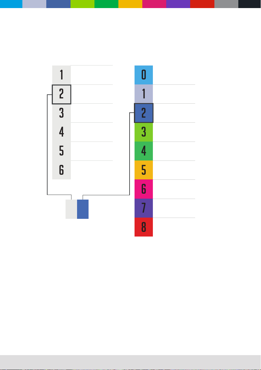
CLF products are applied to ofcial classied IP norm levels. For this product the IP rate is IP22 when using the covers for the chassis
parts. Typical use for outdoor rated stage events with normal weather acceptance. So no heavy rain, because then the water pressure
over exceeds the IP norm.
Condensation/moisture inside housing
Because of high humidity levels during production condensation can occur inside the housing. This is mostly visible on the coldest parts of
the xture, like the front glass or display. To prevent this problem we work with special conditioned areas for outdoor xtures. Because of
the breathing air valves it is still possible to get humidity inside the xture. This will evaporate slowly. Do not put wet xtures in a ightcase,
this will help humidity enter the xture.
Fixtures temperature specication
Make sure the xture is used within its working temperature range of 0° - 40°. Outside this range we cannot guarantee correct operation.
Temporary usage:
Stage event equipment is designed with temporary use in mind. Our product purpose is for theatre, festival, (disco) clubs and indoor &
outdoor concerts. Long term use is possible but keep in mind that it can bring damage to aging materials and affect the coated surface (
i.e. stainless steel). Rubber sealings will be negatively affected after long-term UV exposure and should be checked by qualied service
technicians over time.
Tighten screws too hard will also affect the IP-rating.
solid object Moisture
IP
Ingress
Protection
22
Protected against a solid object greater
than 50mm such as a hand.
Protected against a solid object greater
than 12.5mm such as a finger.
Protected against a solid object greater
than 2.5mm such as a screwdriver.
Protected against a solid object greater
than 1mm such as a wire.
Dust protected. Limited ingress of
dust permitted. Will not interfere
with operation of the equipment.
Dust tight. No ingress of dust.
Protected against vertical falling drops of
water. Limited ingress permitted.
No protection
Protected against water splashes from
all directions. Limited ingress permitted.
Protected against vertical falling drops
of water with enclosure tilted up to 15
degrees from the vertical. Limited
ingress permitted.
Protected against sprays of water up
to 60 degrees from the vertical.
Limited ingress permitted.
Protected against jets of water.
Limited ingress permitted.
Protected against powerful jets of water.
Limited ingress permitted.
Protected against the effects of
immersion in water between 15cm and
1m for 30 minutes.
Protected against the effects of
immersion in water under pressure for
long periods.
123456
012345678

WWW.CLF-LIGHTING.COM 9
Setup
Warning! Read “Safety Information” before installing, powering, operating the xture.
Control panel and menu navigation
The onboard control panel and backlit graphic display are used to set the xture’s DMX address, congure individual xture settings
(personality), read out data and execute service utilities. See “Onboard control menus” for a complete list of menus and commands.
Using the control buttons
• To enter the menu select [MENU].
• Press [UP] and [DOWN] to scroll within a menu or adjust values.
• To enter a menu, select a function or apply a selection, press [ENTER].
• To escape a function or move back one level in the menu structure, press [MODE].
DMX ADDRESS
The DMX address, also known as the start channel, is the rst channel used to receive instructions for the controller. For independent
control, each xture must be assigned its to a separate channel. The DMX address can be congured by using the DMX ADDRESS menu
in the control panel. For setting the DMX address press [ENTER] before you can change the address.
• The xture is fully RDM ready. So when you are using a RDM ready console you can address the unit and read out its complete
status. For RDM functions please refer to the ANSI/ESTAE1.20-2006 standard
WWW.CLF-LIGHTING.COM 10
control panel
Dimmer speed
To select Dimmer Speed, press the ENTER button to conrm. Use the UP/DOWN button to select Smooth or Fast,
press the ENTER button to store. Press the MENU button back to the last menu or let the unit idle one minute to
exit menu mode.
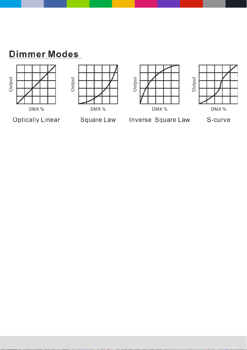
Dimmer curve
To select Dimmer Curve, press the ENTER button to show the DIMMER CURVE on the display. Use the DOWN/UP
button to select the Optically Linear or Square Law or Inverse Square Law or S-Curve. Once the mode has been
selected, press the ENTER button to setup, to go back to the functions without any change press the MENU button
again. Press and hold the MENU button about one second or wait for one minute to exit the menu mode.
ArtNet Setup
To select ArtNet Setup, press the ENTER button to conrm. Use the UP/DOWN button to select Ethernet IP Setup
or ArtNet Port Setup channels mode, press the ENTER button to store. When choose Ethernet IP Setup, use the
UP/DOWN button to select IP Address or Subnet Mask. When choose Art-Net Port Setup, use the UP/DOWN
button to select Net, Subnet or Universe. Press the MENU button back to the last menu or let the unit idle one
minute to exit menu mode.
ArtNet to DMX
To select Artnet to DMX, press the ENTER button to show the DIMMER CURVE on the display. Use the DOWN/
UP button to select the Disable or Enable. Once the mode has been selected, press the ENTER button to setup, to
go back to the functions without any change press the MENU button again. Press and hold the MENU button about
one second or wait for one minute to exit the menu
Software type Shows software version (Vx.x)
Usage time Use of time and use time reset (password)
Temperature Current temperature
RDM.UID Shows the unique ID for the RMD protocoll
Personality
Art-Net
Information
Factory Reset
Resets the xture to its factory default settings.
Here you can set all functions for the xture.
WWW.CLF-LIGHTING.COM 11
Dimmer curve
provides ve dimming options (see picture below):
• Optically Linear - The increase in light intensity appears to be linear as DMX value is increased.
• Squrare Law - Light intensity control is ner at low levels and coarser at high levels.
• Inverse Square Law - Light intensity control is coarser at low levels and nger at high levels.
• S-curve - Light intensity control is nger at low levels and high levels and coarser at medium levels.
WWW.CLF-LIGHTING.COM 12
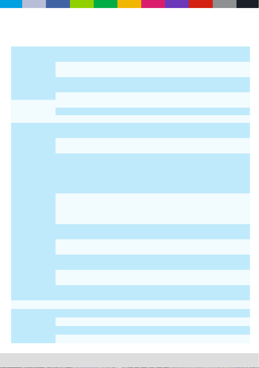
Onboard control menus
DMX Settings
ArtNetSetup Ethernet IP Setup
ArtnetPortSetup
DMX Address 1
512
DMX Channel Mode 57 CH
14 CH
RDM Device ID
DMX Last State
Black Out
Hold
Manual
Fixture Settings
Invert Pixel Order
Disable
Enable
Artnet to DMX
Disable
Enable
Light Mode
Color Calibration
Disable
Enable
Max White Balance
Red
Green
Blue
Dimmer Curve
Optically linear
Square Law
Inverse Square LAw
S-Curve
Dimmer Speed
Smooth
Fast
Invert Tilt
Disable
Enable
Tilt Feedback
Disable
Enable
BI. O. Tilt Moving
Disable
Enable
Fan Mode
Silent
Auto
Auto Test
Manual Mode
Tilt
Dimmer
Strobe
Red

WWW.CLF-LIGHTING.COM 13
Onboard control menus
Display Settings
Inverse No/Yes
Lanuguage
English
Chinese
Temperature Unit °C/°F
Display Warning
Disable
Enable
Fixture Information
LED Temperature -40°C - 125°C
Fixture Usage Time
0
99999
LED Light Time
0
99999
Firmware Version
APP: 1.0
Boot: 1.0
Reset Functions
All
No
Yes
Tilt
No
Yes
Zoom
No
Yes
Factory Setting
Yes
No
Manual Mode
Green
Blue
White
Zoom

WWW.CLF-LIGHTING.COM 14
DMX protocol
14 CH Function Values Description
1 Tilt 000-255 Tilt
2Tilt Fine 000-255 Tilt Fine
3 Zoom 000-255 Zoom
4Dimmer 000-255 Dimmer
5 Dimmer Fine 000-255 Dimmer Fine
6 Strobe
000-031 Shutter closed
032-063 Shutter open
064-095 Strobe effect fast to slow
096-127 Shutter open
128-159 Pulse-effect in sequences
160-191 Shutter open
192-223 Random strobe effect slow to fast
224-255 Shutter open
7Macro
000-008 No function
009-038 Macro 1
039-068 Macro 2
069-098 Macro 3
099-128 Macro 4
129-158 Macro 5
159-187 Macro 6
188-255 Macro 7
8 Foreground Color 000-255
9 Background Color 000-255
10 RED 000-255
11 GREEN 000-255
12 BLUE 000-255
13 WHITE 000-255
14 Special Function
000-060 No function
061-080 Black out when Tilt moving
081-100 Disable Black out when Tilt moving
101-120 Reset All Motor
121-140 Reset Tilt Motor
141-160 Reset Zoom Motor
161-180 Dimmer Speed: Smooth
181-200 Dimmer Speed: Fast
201-225 No Function

WWW.CLF-LIGHTING.COM 15
DMX protocol
57 CH Function Values Description
1 Tilt 000-255 Tilt
2Tilt Fine 000-255 Tilt Fine
3 Tilt Speed
000-007 auto speed
008-247 slow-fast
248-255 auto speed
4Zoom1 000-255 Zoom1
5Zoom2 000-255 Zoom2
6 Dimmer 000-255 Dimmer
7Dimmer Fine 000-255 Dimmer Fine
8Strobe
000-031 Shutter closed
032-063 Shutter open
064-095 Strobe effect fast to slow
096-127 Shutter open
128-159 Pulse-effect in sequences
160-191 Shutter open
192-223 Random strobe effect slow to fast
224-255 Shutter open
9 LED1 RED 000-255 0% ~ 100%
10 LED1 GREEN 000-255 0% ~ 100%
11 LED1 BLUE 000-255 0% ~ 100%
12 LED1 WHITE 000-255 0% ~ 100%
13 LED2 RED 000-255 0% ~ 100%
14 LED2 GREEN 000-255 0% ~ 100%
15 LED2 BLUE 000-255 0% ~ 100%
16 LED2 WHITE 000-255 0% ~ 100%
17 LED3 RED 000-255 0% ~ 100%
18 LED3 GREEN 000-255 0% ~ 100%
19 LED3 BLUE 000-255 0% ~ 100%
20 LED3 WHITE 000-255 0% ~ 100%
21 LED4 RED 000-255 0% ~ 100%
22 LED4 GREEN 000-255 0% ~ 100%
23 LED4 BLUE 000-255 0% ~ 100%
24 LED4 WHITE 000-255 0% ~ 100%
25 LED5 RED 000-255 0% ~ 100%
26 LED5 GREEN 000-255 0% ~ 100%
27 LED5 BLUE 000-255 0% ~ 100%
28 LED5 WHITE 000-255 0% ~ 100%
29 LED6 RED 000-255 0% ~ 100%

WWW.CLF-LIGHTING.COM 16
DMX protocol
57 CH Function Values Description
30 LED6 GREEN 000-255 0% ~ 100%
31 LED6 BLUE 000-255 0% ~ 100%
32 LED6 WHITE 000-255 0% ~ 100%
33 LED7 RED 000-255 0% ~ 100%
34 LED7 GREEN 000-255 0% ~ 100%
35 LED7 BLUE 000-255 0% ~ 100%
36 LED7 WHITE 000-255 0% ~ 100%
37 LED8 RED 000-255 0% ~ 100%
38 LED8 GREEN 000-255 0% ~ 100%
39 LED8 BLUE 000-255 0% ~ 100%
40 LED8 WHITE 000-255 0% ~ 100%
41 LED9 RED 000-255 0% ~ 100%
42 LED9 GREEN 000-255 0% ~ 100%
43 LED9 BLUE 000-255 0% ~ 100%
44 LED9 WHITE 000-255 0% ~ 100%
45 LED10 RED 000-255 0% ~ 100%
46 LED10 GREEN 000-255 0% ~ 100%
47 LED10 BLUE 000-255 0% ~ 100%
48 LED10 WHITE 000-255 0% ~ 100%
49 LED11 RED 000-255 0% ~ 100%
50 LED11 GREEN 000-255 0% ~ 100%
51 LED11 BLUE 000-255 0% ~ 100%
52 LED11 WHITE 000-255 0% ~ 100%
53 LED12 RED 000-255 0% ~ 100%
54 LED12 GREEN 000-255 0% ~ 100%
55 LED12 BLUE 000-255 0% ~ 100%
56 LED12 WHITE 000-255 0% ~ 100%
57 Special function
000-060 No function
061-080 Black out when Tilt moving
081-100 Disable Black out when Tilt moving
101-120 Reset All Motor
121-140 Reset Tilt Motor
141-160 Reset Zoom Motor
161-180 Dimmer Speed: Smooth
181-200 Dimmer Speed: Fast
201-255 No Function

WWW.CLF-LIGHTING.COM 17
Specif
i
cations
Power
Input voltage & rate AC 100 ~ 240V, 50/60Hz
Standby power 31W
“Nominal total power consumption
(at nominal voltage 230V)
450W
Typical current (at nominal voltage 230V) 1,9A
Cos φ
Power plug type
Conguration
LED color RGBW
LED color temperature
LED CRI level
Quantity of LED 12
Dimming frequency
Dimmer resolution 16bit
Optical
Beam angle
Zoom 3.5° – 38°
Photometric
Output @5M 11009 LUX (3,5°) 2752 LUX (3,5°)
Output @10M 553 LUX (38°) 61 LUX (38°)
Heat management
Cooling type Regulated fans
MAX ambient temp (Ta max) 40°
MIN ambient temp (Ta min) 0°
MAX Surface temperature 65°
Menu
Auto program Yes
Static color Yes
Manual calibration
Factory calibration
Strobe speed
Random strobe

WWW.CLF-LIGHTING.COM 18
Specif
i
cations
Control
Control protocol Artnett, RDM ready and DMX 512
DMX channel range 14 and 57 CH
RDM YES
RDM compliance USIT
WDMX NO
ACN NO
DMX input connection 3 & 5 Pin XLR
Data input (artnet, SACN) RJ45
Hardware
Interface OLED display with battery backup
Software upload method Via DMX input
Installation
IP rating IP22
Housing
Safety attachment point yes
Physical
Net product weight 17 KG
Machine dimensions - length 1000 mm
Machine dimensions - depth 113 mm
Machine dimensions - height 278 mm
Accessories
included items User manual, power cord
Approvals
Approved certications CE / ROHS
Table of contents
Other CLF Lighting Dj Equipment manuals


