Manual-6
OPERATING INSTRUCTIONS
INITIAL OPERATION
For starters, connect a CD player to LINE 1 Input and set
the PHONO/LINE switch to LINE. If a turntable is used, set
this switch to PHONO. Make sure all faders are set to zero, the
MIC and EQ are disengaged (switches out) and all rotary con-
trols are either fully CCW (LEVEL controls) or in their center
detents (EQs), whichever applies. Leave the rear panel INPUT
TRIMS at full CW (factory preset). Switch the Channel A IN-
PUT SELECT to PH/LN 1. Simultaneously raise the Channel
A fader and the MASTER LEVEL fader. Before you cover much
travel on the faders you should begin to hear the results. If you
do not, shut everything down and recheck your connections,
power to the mixer (look for the yellow POWER light) and an-
cillary devices (EQs, crossovers, power amplifiers, etc.) Once you
have established an output from whatever is connected to LINE
1, go ahead and try the other Inputs.
INPUT FADERS
e Input Channel faders should be set near their maximum
levels to preclude requiring excessive gain from the Output stage.
Achieve optimum noise performance by running the majority of
the gain on the Input stages. Taking the least amount of gain on
the Output stage ensures that the system doesn’t have to amplify
the unavoidable noise generated by the input buffers and sum-
ming amplifiers.
INPUT TRIMS
e TRIMS allow various devices to drive each Input equal-
ly. If you have two CD players, you might want to play the same
CD on each player. Now lower the TRIM on the louder player
(the other one should be up all the way) so the MP 22z meter
peaks match for both players. You can use a similar method with
the same recording on different formats to match a turntable
to a CD, or a cassette to a CD or video deck. If your source has
an Output VU of its own, push the Input Channel fader all the
way up, set the MASTER LEVEL control to “6” (unity gain),
and adjust the TRIM so that both meters reach 0 dB at the same
time.
HEADPHONE CONTROL (CUE) SYSTEM
First, you must have signal present at one of the Inputs.
(Well, at least you do to make sure it works.) Depressing the
CUE switch for the respective Input Channel presents this
signal to the headphone amplifier. An LED illuminates next
to the Input CUE switch, attesting to the fact that it is pushed
down. ere are two choices of listening to the CUE. With the
STEREO/MONO switch down, you get Mono Cue in the Left
ear and Mono Program in the Right, and PAN controls the
amount of each. With this switch up, you get Stereo Program in
both ears or Stereo Cue in both ears, depending on the rotation
of the PAN control. e overall volume is then controlled by the
HEADPHONE LEVEL control.
When a CUE is active at either Input Channel, and if the
Meter CUE/PROGAM switch is down, the monoed Cue signal
is routed to the LEFT side of the PEAK dBu Meter, while
monoed Program is displayed on the RIGHT. is is useful to
match a source before it is faded in to the level of the program
currently playing, or for visual beat matching.
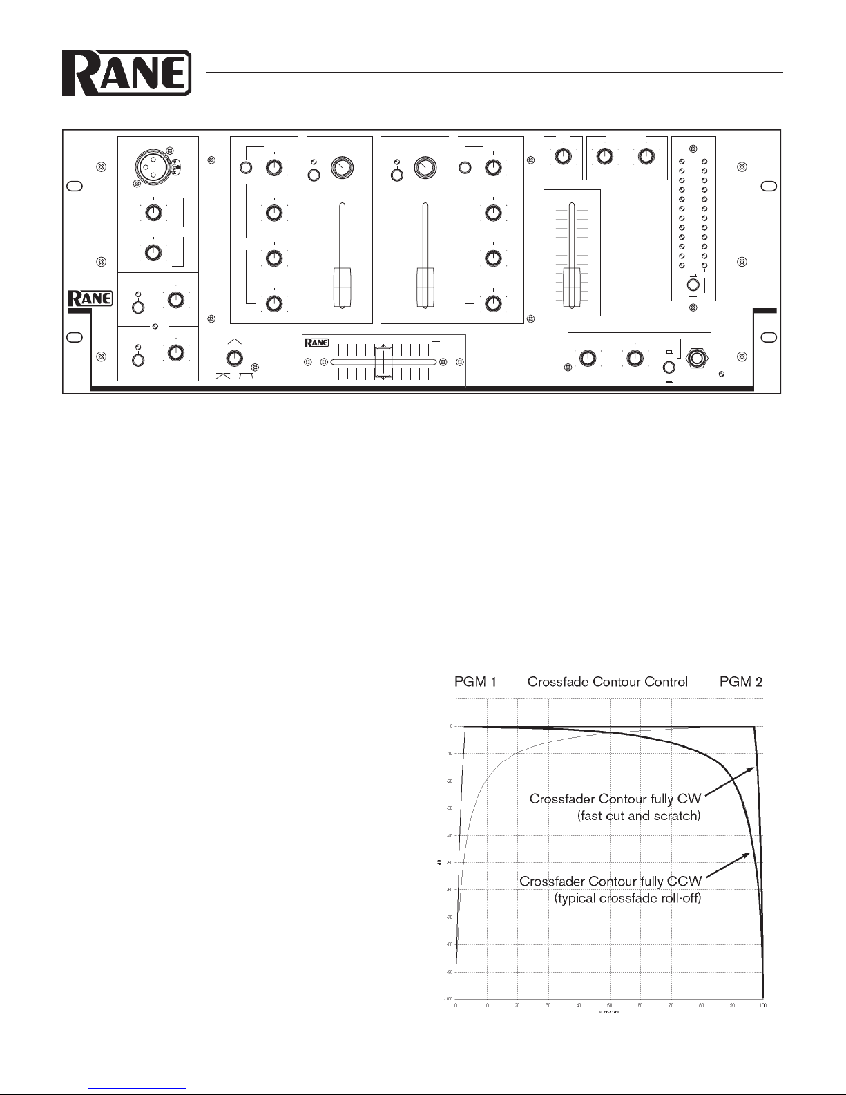
USING THE CROSSFADER
e volume of the two Input Channels begins from the fad-
ers on Channels A and B. eir outputs are under the control of
the Crossfader. When in its left-most position, only Channel A
appears at the Outputs. In the center, both Channels are present
in equal levels, and only Channel B will be heard once the far
right is reached. With the CROSSFADER CONTOUR set to
the full ccw position, the sound pressure level does not change
as this transition progresses. See Figure 1 on page Manual-1 for
response curves.
MICROPHONE OPERATION.
Connect the mic to the appropriate connector. Leave the
MASTER LEVEL fader in roughly the same location as it was
for the music that’s been playing, press the MIC ENGAGE
switch (notice the flashing LED) and adjust the MAIN MIC (or
REMOTE MIC) LEVEL. e tonal balance may be adjusted
via the MIC EQ controls. Modifying the sound of the mic in
this way won’t affect the EQ of the music in the system. e
three Equalizer sections (Mic and Input A and B Channels) are
totally independent. When the mic is not in use, release the MIC
ENGAGE switch again to its up position, extinguishing the
LED. Should the microphone preamp become overloaded, the
red LED Overload light illuminates. If this is a problem, lower
the appropriate MIC LEVEL control and increase the level of the
MASTER LEVEL fader to restore desired microphone level.
ZONE OUTPUTS
e ZONE OUTPUTS are additional stereo Outputs with
their own ZONE LEVEL controls that can be routed to am-
plifers that feed the bar, another tape recorder, etc. If you would
like the MIC and AUX signals to be removed from the ZONE 1
OUTPUT place the rear panel switch in the NO position. In the
YES position, you will get MIC and AUX signals in ZONE 1.
©Rane Corporation 10802 47th Ave. W., Mukilteo WA 98275-5098 TEL 425-355-6000 FAX 425-347-7757 WEB www.rane.com
103293