CLF Lighting POSEIDON HYBRID User manual

WWW.CLF-LIGHTING.COM V2.0 APRIL 2021
POSEIDON hybrid manual
hybrid

table of CONTENTS
Dimensions 1
Safety Instruction 2
Fixture overview 4
Introduction 5
AC Power 5
Power voltage 5
Power cables 6
Relaying power to other devices 6
Data link 6
Tips for reliable data transmission 6
Physical installation 7
Fastening the xture to a at surface 7
Outdoor IP-rated xtures 8
Condensation/moisture inside housing 8
Fixtures temperature specication 8
Setup 9
Control panel and menu navigation 9
DMX address setting 9
Onboard control menus 10
DMX protocol 17
Gobo overview 23
Photometrics 24
Circuit connection diagram 25
Specif
i
cations 26
WWW.CLF-LIGHTING.COM

Dimensions
in millimeters
WWW.CLF-LIGHTING.COM 1
hybrid
Safety Instruction
WWW.CLF-LIGHTING.COM 2
WARNING!
Read the safety precautions in this section before
installing, powering, operating or servicing this
product.
The following symbols are used to identify important safety information on the product and in this manual:
DANGER!
Safety hazard.
Risk of severe
injury or death.
DANGER!
Hazardous
voltage. Risk of
lethal or severe
electric shock.
WARNING!
Fire hazard.
WARNING!
Burn hazard. Hot
surface. Do not
touch.
WARNING!
Wear protective
eyewear.
WARNING!
Refer to user
manual.
This product is for professional use only. It is not for household use.
This product presents risks of severe injury or death due to re and burn hazards, electric shock and falls.
Read this manual before installing, powering or servicing the xture, follow the safety precautions listed below and
observe all warnings in this manual and printed on the xture. If you have questions about how to operate the xture
safely, please contact your supplier.
PROTECTION FROM ELECTRIC SHOCK
• Disconnect the xture from AC power before removing or installing any cover or part.
• Always ground (earth) the xture electrically.
• Use only a source of AC power that complies with local building and electrical codes and has both overload and
ground-fault (earth-fault) protection.
• Before using the xture, check that all power distribution equipment and cables are in perfect condition and rated
for the current requirements of all connected devices.
• Power input and throughput cables must be rated 20A minimum, have three conductors 1.5 mm² (16 AWG)
minimum conductor size and an outer cable diameter of 5 - 15 mm. Cables must be hard usage type (SJT or
equivalent) and heat-resistant to 90°C minimum.
• Use only PowerCON TRUE 1 ® cable connectors to connect to power input sockets. Use only PowerCON TRUE1
® cable connectors to connect to power throughput sockets.
• Isolate the xture from power immediately if the power plug or any seal, cover, cable, or other component is
damaged, defective, deformed, wet or showing signs of overheating. Do not reapply power until repairs have been
completed.
• Refer any service operation not described in this manual to a qualied technician.
• Socket outlets used to supply xture xtures with power or external power switches must be located near the
xtures and easily accessible so that the xtures can easily be disconnected from power.
WWW.CLF-LIGHTING.COM 3
PROTECTION FROM BURNS AND FIRE
• The exterior of the xture becomes hot during use. Avoid contact by persons and materials.
Allow the xture to cool for at least 5 minutes before handling.
• Keep all combustible materials (e.g. fabric, wood, paper) at least 1 metres away from the xture.
• Keep ammable materials well away from the xture.
• Ensure that there is free and unobstructed airow around the xture.
• Do not illuminate surfaces within 8 metres of the xture.
• Do not attempt to bypass thermostatic switches or fuses.
• If you relay power from one xture to another using power throughout sockets, do not connect more than ve
xtures in total to eachother in an interconnected chain.
• Connect only other xtures to xture power throughout sockets.
• Do not stick lters, masks or other materials onto any optical component.
• Do not modify the xture in any way not described in this manual.
PROTECTION FROM INJURY
• Fasten the xture securely to a xed surface or structure when in use. The xture is not portable when installed.
• Ensure that any supporting structure and/or hardware used can hold at least 10 times the weight of all the devices
they support.
• Allow enough clearance around the head to ensure that it cannot collide with an object or another xture when it
moves.
• Check that all external covers and rigging hardware are securely fastened.
• Block access below the work area and work from a stable platform whenever installing, servicing or moving the
xture.
• Do not operate the xture with missing or damaged covers, shields or any optical component.
lamp life
• Lamp life can vary, caused by many factors. For example external temperature, humidity, lamp strikes, dimming or
power/voltage.
WWW.CLF-LIGHTING.COM 4
Fixture overview
WWW.CLF-LIGHTING.COM 5
Introduction
powerful outdoor HYBRID
■SMOOTH CMY COLOR MIXING
■FIXED COLOR WHEEL
■2 GOBO WHEELS
■3 PRISMS (LINEAR, 4-FACET & 8-FACET)
■FROST
■2° – 45° ZOOM WITH AUTOFOCUS
■ANIMATION EFFECT
Using for the rst time
Warning! Read “Safety Information” before installing, powering, operating or servicing the xture. Before applying power to the
xture:
Check that the local AC mains power source is within the xture’s power voltage and frequency ranges.
See “Power cables and power plug” on page 6. Install a PowerCON TRUE1 ® power input connector power cable.
AC Power
Warning! Read “Safety Information” starting on before connecting the xtures to AC mains power.
Warning! For protection from electric shock, the xture must be grounded (earthed). The power distribution
circuit must be equipped with a fuse or circuit breaker and ground-fault (earth-fault) protection.
Warning! Socket outlets or external power switches used to supply the xture with power must be located near
the xture and easily accessible so that the xtures can easily be disconnected from power.
Important! Do not insert or remove live PowerCON TRUE 1 ® connectors to apply or cut power, as this may
cause arcing at the terminals that will damage the connectors.
Important! Do not use an external dimming system to supply power to the xture, as this may cause damage to
the xture that is not covered by the product warranty.
The xture can be hard wired to a electrical installation if you want to install it permanently, or a power plug that is
suitable for the local power outlets can be installed on the power cable.
Power voltage
Warning! Check that the voltage range specied on the xture serial number label matches the local AC mains power
voltage before applying power to the xture.
The xtures accepts AC mains power at 100-240V nominal, 50/60 Hz. Do not apply AC mains power to the xture at any
other voltage than specied.
WWW.CLF-LIGHTING.COM 6
Power cables
Power input and throughput cables must be rated 16A minimum, have three conductors 1.5 mm² (16 AWG) minimum conductor size and
an outer cable diameter of 5 - 15 mm. Cables must be hard usage type (SJT or equivalent) and heat- resistant to 90°C minimum. In the
EU the cable must be HAR approved or equivalent.
If you install a power plug on the power cable, install a grounding-type (earthed) plug that is rated 16A minimum. Follow the plug
manufacturer’s instructions. Table 1 shows standard wire color-coding schemes and some possible pin identication schemes; if pins are
not clearly identied.
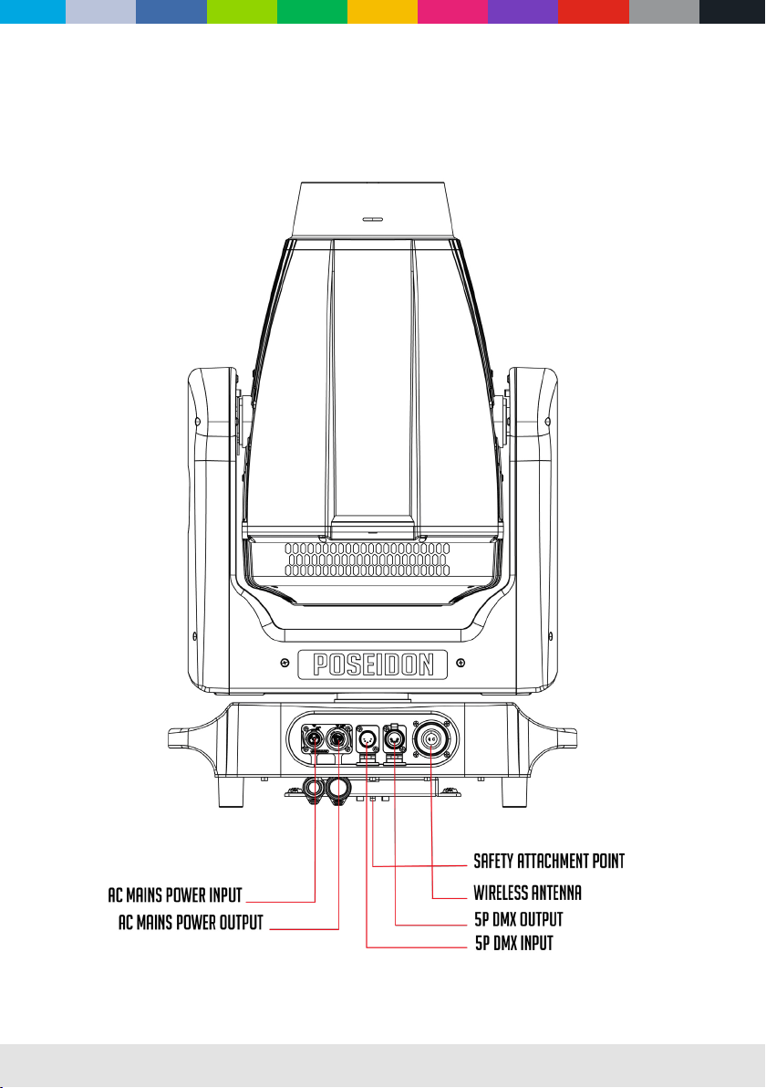
Data link
A DMX 512 data link is required in order to control a xture via DMX. The xture has 5-pin XLR connectors for DMX data input and output.
The pin-out on all connectors is pin 1 = shield, pin 2 = cold (-), and pin 3 = hot (+) Pins 4 and 5 in the 5-pin XLR connectors are not in use.
Tips for reliable data transmission
To connect the xture to data:
1. Connect the DMX data output from the controller to the 5-pin XLR connector of the nearest xture.
2. Connect the DMX output of the rst xture to the DMX input of the next xture and continue connecting xtures.
Relaying power to other devices
Warning! Do not connect more than ve xtures in total in one interconnected chain. Power can be relayed to another device via the
PowerCON TRUE 1 ® throughput socket.
If you daisy chain the xtures in a chain so that they all draw AC mains power via the rst xture, certain points must be respected:
A heavy duty, three-conductor, 16 AWG or 1.5 mm2 cable with SJT or equivalent cable jacket must be used to connect the rst xture to
AC mains power. PowerCON TRUE1 ® connectors must be used to draw AC mains power from the xtures power throughput socket and
yellow PowerCON TRUE 1 ® connectors must be used to supply power at the xture’s power input sockets.
Wire Color (EU models) Wire Color (US models) Conductor Symbol
Brown Black Live L
Blue White Neutral N
Yellow/Green Green Ground (earth) or
Table 1: Wire color-coding and power connections

WWW.CLF-LIGHTING.COM 7
Physical installation
Warning! The xture must be either fastened to a at surface such as a stage or wall, or clamped to a truss or
similar structure in any orientation using a rigging clamp.
Warning! Always attach an approved safety cable to one of the safety cable attachment points on the base.
Do not illuminate surfaces within 6 meters of the xture. Ensure that ammable materials (wood, fabric, paper, etc.) are
minimum 1 meters from the xture and allow a free airow around the xture.
Fastening the xture to a at surface
The xture can be fastened to a xed at surface that is oriented at any angle. Check that the surface can
support at least 10 times the weight of all xtures and equipment to be installed.
Warning! The supporting surface must be hard and at or cooling may be blocked, which will cause overheating.
Fasten the xture securely. Do not place it on unstable surfaces. Always attach a securely anchored safety cable to the
safety cable attachment point.
Block access under the construction area. Work from a stable platform, hang the xture on a truss with the
arrow on the base towards the area to be illuminated. Tighten the rigging clamp.

WWW.CLF-LIGHTING.COM 8
Outdoor IP-rated xtures
CLF products are applied to ocial classied IP norm levels. For this product the IP rate is IP65 when using the covers for the chassis
parts. IP65 means according classied norm: shielded against dust and pressurized water from any side. Typical use for outdoor rated
stage events with normal weather acceptance. So no heavy rain, because then the water pressure over exceeds the IP norm.
Condensation/moisture inside housing
Because of high humidity levels during production condensation can occur inside the housing. This is mostly visible on the coldest parts of
the xture, like the front glass or display. To prevent this problem we work with special conditioned areas for outdoor xtures. Because of
the breathing air valves it is still possible to get humidity inside the xture. This will evaporate slowly. Do not put wet xtures in a ightcase,
this will help humidity enter the xture.
Fixtures temperature specication
Make sure the xture is used within its working temperature range. Outside this range we cannot guarantee correct operation.
Temporary usage:
Stage event equipment is designed for temporary outdoor use. Materials are not designed for long-term exposure to heavy weather
conditions. Rubber covers will be negatively aected by long-term UV exposure and should be checked by qualied service technicians
over time. Tightening screws too hard will negatively aect the IP-rating.
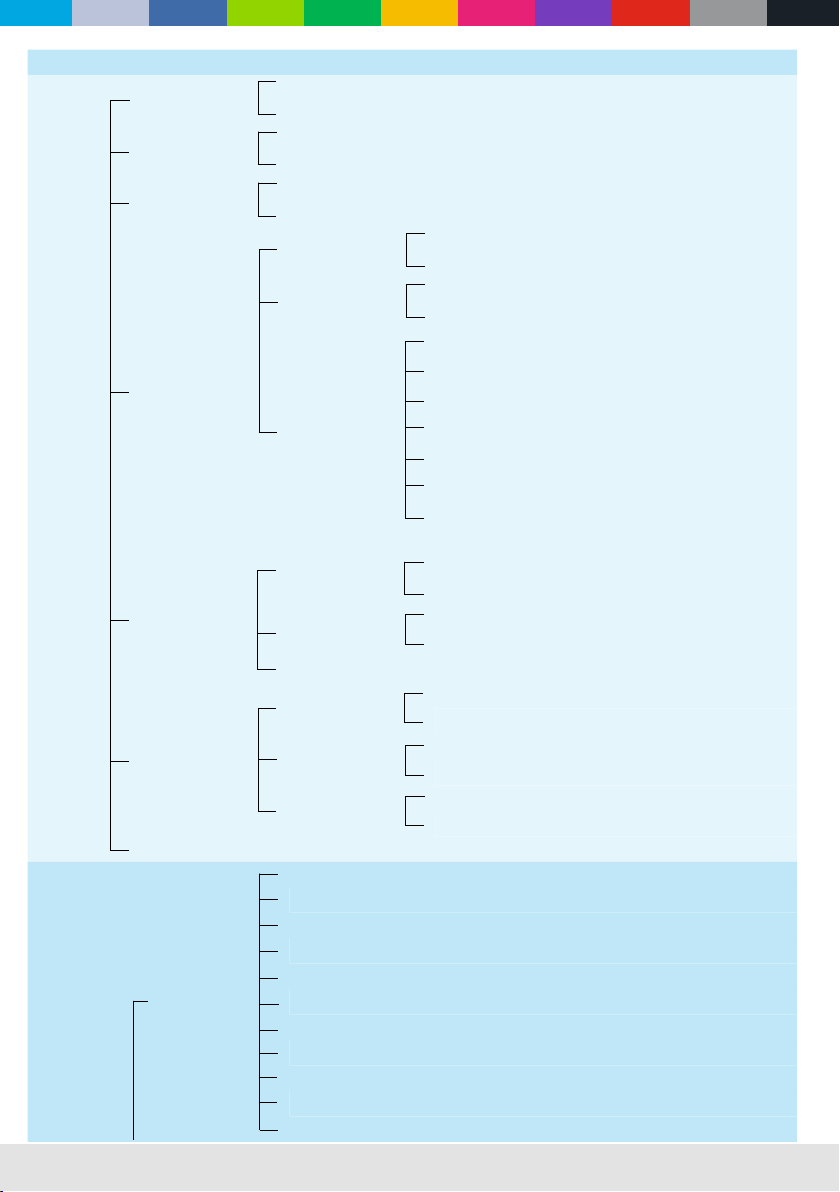
solid object Moisture
12345678
IP
Ingress
Protection
65
Protected against a solid object greater
than 50mm such as a hand.
Protected against a solid object greater
than 12.5mm such as a finger.
Protected against a solid object greater
than 2.5mm such as a screwdriver.
Protected against a solid object greater
than 1mm such as a wire.
Dust protected. Limited ingress of
dust permitted. Will not interfere
with operation of the equipment.
Dust tight. No ingress of dust.
Protected against vertical falling drops of
water. Limited ingress permitted.
Protected against water splashes from
all directions. Limited ingress permitted.
Protected against vertical falling drops
of water with enclosure tilted up to 15
degrees from the vertical. Limited
ingress permitted.
Protected against sprays of water up
to 60 degrees from the vertical.
Limited ingress permitted.
Protected against jets of water.
Limited ingress permitted.
Protected against powerful jets of water.
Limited ingress permitted.
Protected against the effects of
immersion in water between 15cm and
1m for 30 minutes.
Protected against the effects of
immersion in water under pressure for
long periods.
123456

WWW.CLF-LIGHTING.COM 9
Setup
Warning! Read “Safety Information” before installing, powering, operating the xture.
Control panel and menu navigation
The onboard control panel and backlit graphic display are used to adjust the DMX address, xture settings (personality), service utilities.
See “Onboard control menus” for a complete list of menus and commands.
Using the control buttons:
• To enter the menu select [ENTER].
• Press [UP], [DOWN], [LEFT] AND [RIGHT] to scroll within a menu or adjust values.
• To enter a menu, select a function or apply a selection, press [ENTER].
• To escape a function or move back one level in the menu structure, press [LEFT].
DMX address setting
The DMX address is the rst channel used to receive instructions from the controller. For independent control, each xture must be
assigned to a separate channel. The DMX address can be congured by using the DMX ADDRESS menu in the control panel.
• NO DMX: Display ashes and shows at ‘DMX: X‘.
• DMX: Display backlight turns o and shows ‘DMX: V‘.
• The xture is fully RDM ready. For RDM functions please refer to the ANSI/ESTA E1.20-2006 standard.

WWW.CLF-LIGHTING.COM 10
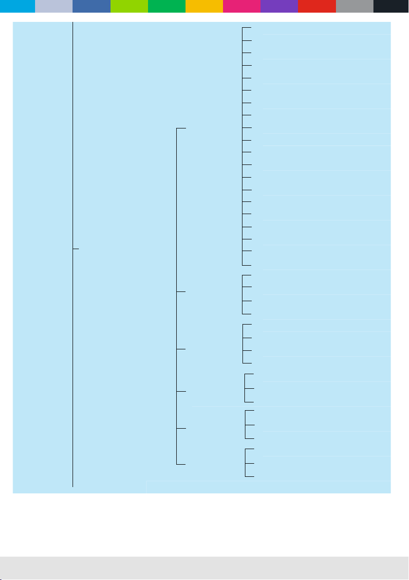
Onboard control menus
Main menu Menu level 1 Menu level 2 Menu level 3 Menu level 4
DMX
Settings
001 - 512
DMX signal mode
Wired
Wireless Don’t use two sources at the same time
Return (ESC)
Information
Checksum error
Power hours
Total Hours: ****H
Rst Hours: ****H
Lamp Hours
Total Hours: ****H
Rst Hours: ****H
Lamp Strikes
Total Strikes: ****H
Rst Strikes: ****H
Temperature
E-ballast: 000.0
Out TEMP: 000.0
In TEMP: 000.0
Logged
temperature
E-ballast
Cur TEMP: ***
Max TEMP: ***
Min TEMP:***
Out temperature
Cur TEMP: ***
Max TEMP: ***
Min TEMP:***
In temperature
Cur TEMP: ***
Max TEMP: ***
Min TEMP:***
Fan information
Return (ESC)
Lamp fan
1. Power: **.*V
2. Speed: **.*%
3. Speed: ****R
Out fan
1. Power: **.*V
2. SP-Fan 1: **.*%
3. SP-Fan 2: **.*%
4. SP-Fan 1: ****R
5. SP-Fan 2: ****R
In fan
1. Power: **.*V
2. SP-Fan 1: **.*%
3. SP-Fan 2: **.*%
4. SP-Fan 1: ****R
5. SP-Fan 2: ****R
Return (ESC)

WWW.CLF-LIGHTING.COM 11
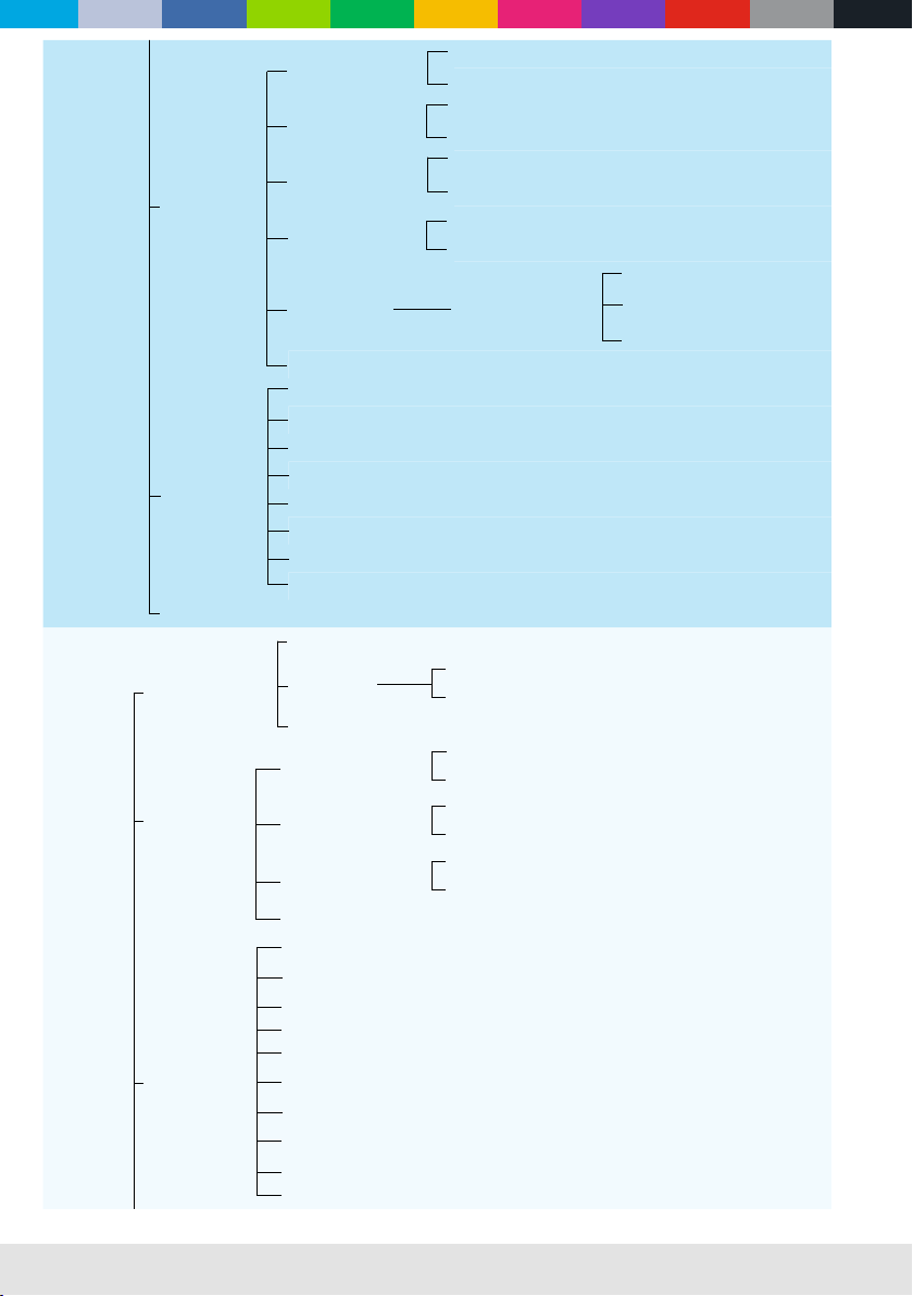
Information DMX Live
1. Pan***
2. Pan Fine ***
3. Tilt ***
4. Tilt Fine ***
5. P/T Speed ***
6. Functions ***
7. Cyan***
8. Magenta***
9. Yellow ***
10. ColorWheel ***
11. NC ***
12. Eect ***
13. Eect Rot ***
14. Static Gob***
15. Rot Gobo ***
16. Gobo Rot ***
17. Prism 1 ***
18. Prims1 Rot ***
19. NC ***
20. NC ***
21. PrismMacro ***
22. Macro Rot ***
23. Frost ***
24. Zoom ***
25. Zoom Focus ***
26. Focus ***
27. Focus Fine ***
28. Focus 2 ***
29. AutoFocus ***
30. Shutter ***
31. Dimmer ***
32. DimmerFine ***
33. NC ***
System version
XY: V*.**
Fan: V*.**
Gobo: V*.**
CMY: V*.**
Prism: V*.**
Display: V*.**
Return (ESC)
WWW.CLF-LIGHTING.COM 12
Main menu Menu level 1 Menu level 2 Menu level 3 Menu level 4
Personality
Auto lamp on
O
On
Display lock
O
On
Leak light protect
O
On
Wireless options
Wireless on/o
O
On
Wireless settings
Idle
Unlink transmitter
Wireless status
Wireless o
Not found sender
No DMX receiving
Connected to sender
No DMX receiving
Connected to sender
DMX receiving
P/T Invert
Pan invert
O
On
Tilt invert
O
On
Return (ESC)
Display
Backlight
Always on
Auto o (15s)
Rotate
Normal
Rotate 180
Backlight blink
On
O
Return (ESC)
Manual control Channel control
1. Pan ***
2. Pan Fine***
3. Tilt ***
4. Tilt Fine ***
5. P/T Speed ***
6. Functions ***
7. Cyan ***
8. Magenta ***
9. Yellow ***
10. ColorWheel ***
11. NC ***

WWW.CLF-LIGHTING.COM 13
Manual control
Channel control
12. Eect ***
13. Eect Rot ***
14. Static Gob***
15. Rot Gobo***
16. Gobo Rot ***
17. Prism1 ***
18. Prism1 Rot***
19. NC ***
20. NC ***
21. PrismMacro ***
22. Macro Rot ***
23. Frost ***
24. Zoom ***
25. Zoom Fine ***
26. Focus ***
27. Focus Fine ***
28. Focus 2 ***
29. AutoFocus ***
30. Shutter ***
31. Dimmer* **
32. Dimmer Fine
33. NC ***
Return (ESC)
Program editor Editor Scene edit
Sequence ***
1. Pan ***
2. Pan Fine ***
3. Tilt ***
4. Tilt Fine ***
5. P/T Speed ***
6. Functions ***
7. Cyan ***
8. Magenta ***
9. Yellow ***
10. ColorWheel ***
11. NC ***
12. Eect ***
13. Eect Rot ***
14. Static Gob ***
15. Rot Gobo ***
WWW.CLF-LIGHTING.COM 14
Manual control Program Editor Editor
Scene Edit
16. Gobo Rot ***
17. Prism 1 ***
18.Prism 1 Rot ***
19. NC
20. NC
21. PrismMacro
22. Macro Rot
23. Frost
24. Zoom
25. Zoom Fine
26. Focus
27. Focus Fine
28. Focus 2
29. Autofocus
30. Shutter
31. Dimmer
32. DimmerFine ***
33. NC ***
Save the scene
Return
Wait time
Static Scene ***
Time : *** SEC
Save the time
Return (ESC)
Fade time
Static Scene ***
Time : *** SEC
Save the time
Return (ESC)
Copy scene
Static Scene ***
Save the time
Return (ESC)
Paste scene
Static Scene ***
Paste Scene ***
Return (ESC)
Clear scene
Static Scene ***
Clear Scene
Return (ESC)
Return (ESC)
WWW.CLF-LIGHTING.COM 15
Manual control Program editor
Program run mode
Program 1
Program Captured DMX
Run Program
No
Yes
Stop Program
No
Yes
Run on power on
No
Yes
Capture DMX Saved DMX Data
Static Scene: ***
Saved Scene from DMX
Return (ESC)
Return (ESC)
System reset
Reset all
Pan/Tilt reset
Gobo reset
Color reset
Dimmer reset
Zoom reset
Eect reset
Return (ESC)
Return (ESC)
Service
Error information
Error list
Empty list
No
Yes
Return (ESC)
Reset timers
Reset power hours
No
Yes
Reset lamp hours
No
Yes
Reset lamp strikes
No
Yes
Return (ESC)
Calibration
Pan 000-255
Tilt 000-255
Dimmer1 000-255
Dimmer2 000-255
Cyan 000-255
Magenta 000-255
Yellow 000-255
Color 000-255
Static gobo 000-255
Rotate gobo 000-255
WWW.CLF-LIGHTING.COM 16
Service
Calibration
Eect 000-255
Prism 1 000-255
NC 000-255
Frost 000-255
NC 000-255
Focus 000-255
Sta gobo Focus 000-255
Sta gobo Zoom 000-255
Rot gobo Focus 000-255
Rot gobo Zoom 000-255
Eect Focus 000-255
Eect Zoom 000-255
Return (ESC)
Lamp adjust mode
O
On
Factory
Load default Password: 1111
Reset total timers
Total power Hr
Total lamp Hr
Total lamp Str
Return (ESC)
Clear logged temperature Password: 3255
Firmware update Password: 7273
Return (ESC)
Return (ESC)
Lamp
O
On
Test
Test P/T STEP ***
Test eect STEP ***
Test all STEP ***
Return (ESC)
Rotate
display
Normal
Rotate 180

WWW.CLF-LIGHTING.COM 17
DMX protocol
Channel Function Value Setting Remark
1Pan 0-255 0-100%
2Pan Fine 0-255 0-100%
3 Tilt 0-255 0-100%
4Tilt Fine 0-255 0-100%
5
0 Standard mode (0=Default)
Movement Speed/Time 1 Max. Speed Mode
2-255 Speed from max to min
6Function 0-130 No function
130-139 Lamp on
140-149 Pan/tilt reset
150-159 color system reset
160-169 gobo wheel reset
170-179 Dimmer/shutter reset
180-189 Zoom/focus/frost/ prism reset
190-199 Eect wheel reset
200-209 Total reset
210-229 No function
230-239 Lamp o
240-255 No function
7Cyan 0-255 0 to 100% cyan
8Magenta 0-255 0 to 100% magenta
9Yellow 0-255 0 to 100% yellow
10 Color wheel 0-4 Open
5-8 Open + Red
9-12 Red
13-17 Red + Orange
18-21 Orange
22-25 Orange + Aquamarine
26-29 Aquamarine
30-34 Aquamarine + Green
35-38 Green
39-42 Green + Light Green
43-46 Light Green
47-51 Light Green + Lavender
52-55 Lavender

WWW.CLF-LIGHTING.COM 18
Channel Function Value Setting Remark
10 Color wheel 56-59 Lavender + Pink
60-63 Pink
64-68 Pink + Yellow
69-72 Yellow
73-76 Yellow + Magenta
77-81 Magenta
82-85 Magenta + Cyan
86-89 Cyan
90-93 Cyan + CTO 260
94-98 CTO 260 / CTO2
99-102 CTO 260 + CTO 190 / CTO2 + CTO1
103-106 CTO 190 / CTO1
107-110 CTO 190 + CTB 8000 / CTO1 + CTB
111-115 CTB 8000 / CTB
116-119 CTB 8000 + Blue
120-123 Blue
124-127 Blue + White
128-191 CCW Fast to slow rotation
192-255 CW Slow to fast rotation
11 No function
12 Eect Wheel Positioning 0-19 No function
20-255 Full eect
13 Eect Wheel Rotation 0 No rotation
1-127 Forwards rotation from fast to slow
128 No rotation
129-255 Backwards rotation from slow to fast
14 Static Gobo Wheel 0-3 Open
4-9 Beam reducer 1
10-15 Beam reducer 2
16-21 Beam reducer 3
22-27 Beam reducer 4
28-33 Gobo 1 (dots)
34-39 Gobo 2 (star)
40-45 Gobo 3 (sun)
46-51 Gobo 4 (horizontal line)
52-57 Gobo 5 (vertical line)
58-63 Gobo 6 (twisted star)
Table of contents
Other CLF Lighting Light Fixture manuals

Popular Light Fixture manuals by other brands

Intelight
Intelight STARLET EXTERNAL LED SO Installation and maintenance instructions

MOLTO LUCE
MOLTO LUCE TRAIL MOVA INSERT Mounting instruction

Larson Electronics
Larson Electronics EPL-EMG-HB-50LED-RT-WLM instruction manual

Manta
Manta TOUCH MD1 instruction manual

Eurotops
Eurotops 25 296 manual

Cooper Lighting
Cooper Lighting SSRxx installation instructions


