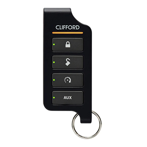
Clifford Polaris 4 User manual
Other Clifford Car Alarm manuals

Clifford
Clifford SuperNova Auto Security SuperNova User manual

Clifford
Clifford Nova III User manual

Clifford
Clifford 3606X User manual

Clifford
Clifford intelliguard 800-IQ User manual
Clifford
Clifford AvantGuard 2 User manual

Clifford
Clifford Matrix 12.5x User manual

Clifford
Clifford Centurion User manual
Clifford
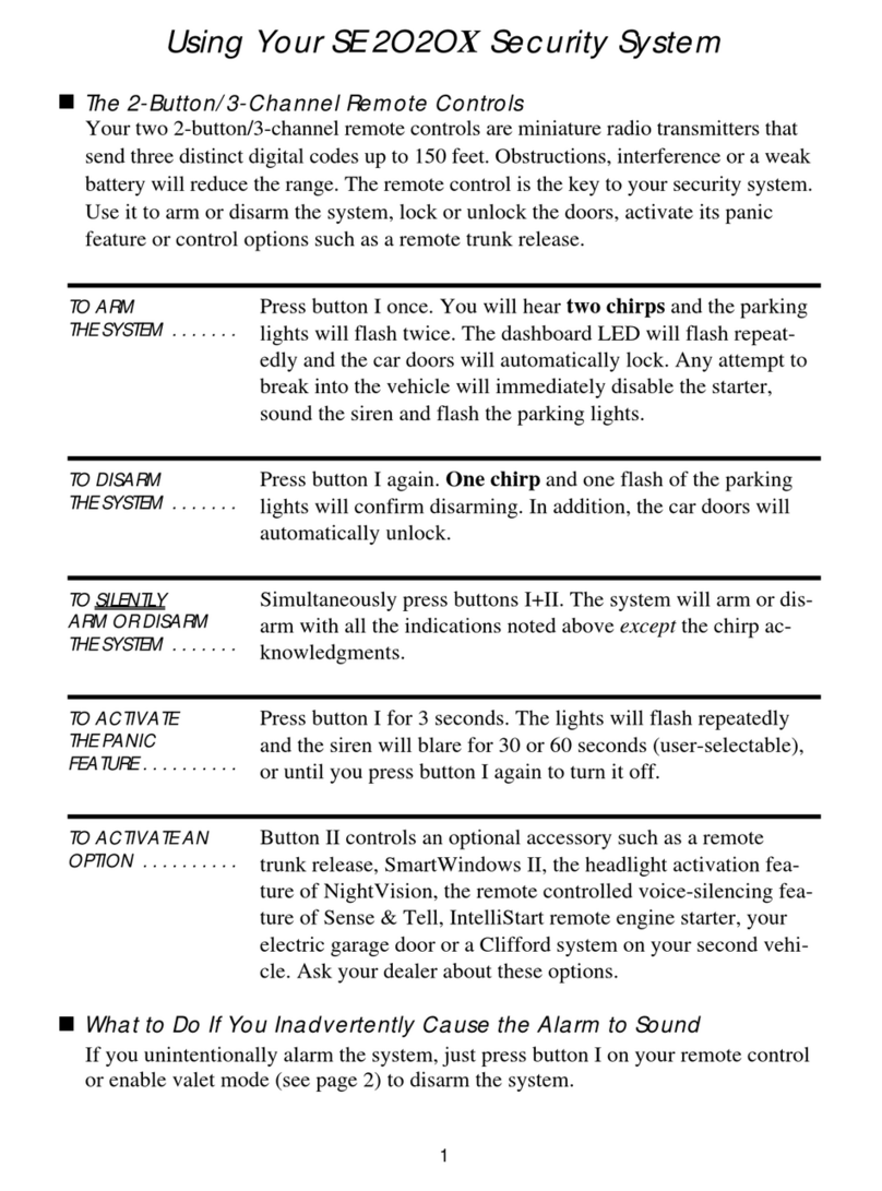
Clifford SE 2020 Special Edition User manual
Clifford
Clifford CallGuard User manual

Clifford
Clifford Concept 100 User manual

Clifford
Clifford ACE 7500 User manual

Clifford
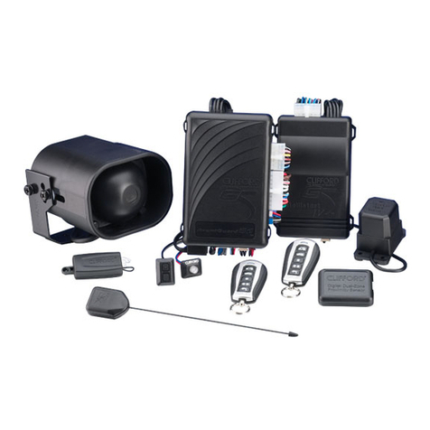
Clifford 4706X Responder LC3 User manual
Clifford
Clifford AvantGuard II User manual

Clifford
Clifford AvantGuard 4 User manual

Clifford
Clifford 4806X User manual
Clifford
Clifford Matrix 1 User manual
Clifford
Clifford Model RSX3.5 User manual

Clifford
Clifford Responder LE 5806X User manual

Clifford
Clifford Concept 40 User manual

Clifford
Clifford Arrow II User manual
Popular Car Alarm manuals by other brands

Ultra Start
Ultra Start 2500M SERIES install guide

Ultra Start
Ultra Start 650 Series owner's manual

Audiovox
Audiovox Prestige Platinum+ APS-511C owner's manual

Sparkrite
Sparkrite SRA8 Guide

Viper
Viper 4708V owner's manual

Federal Signal Corporation
Federal Signal Corporation Pathfinder Siren Series Installation and maintenance manual


