ClimateMaster AG Series Manual
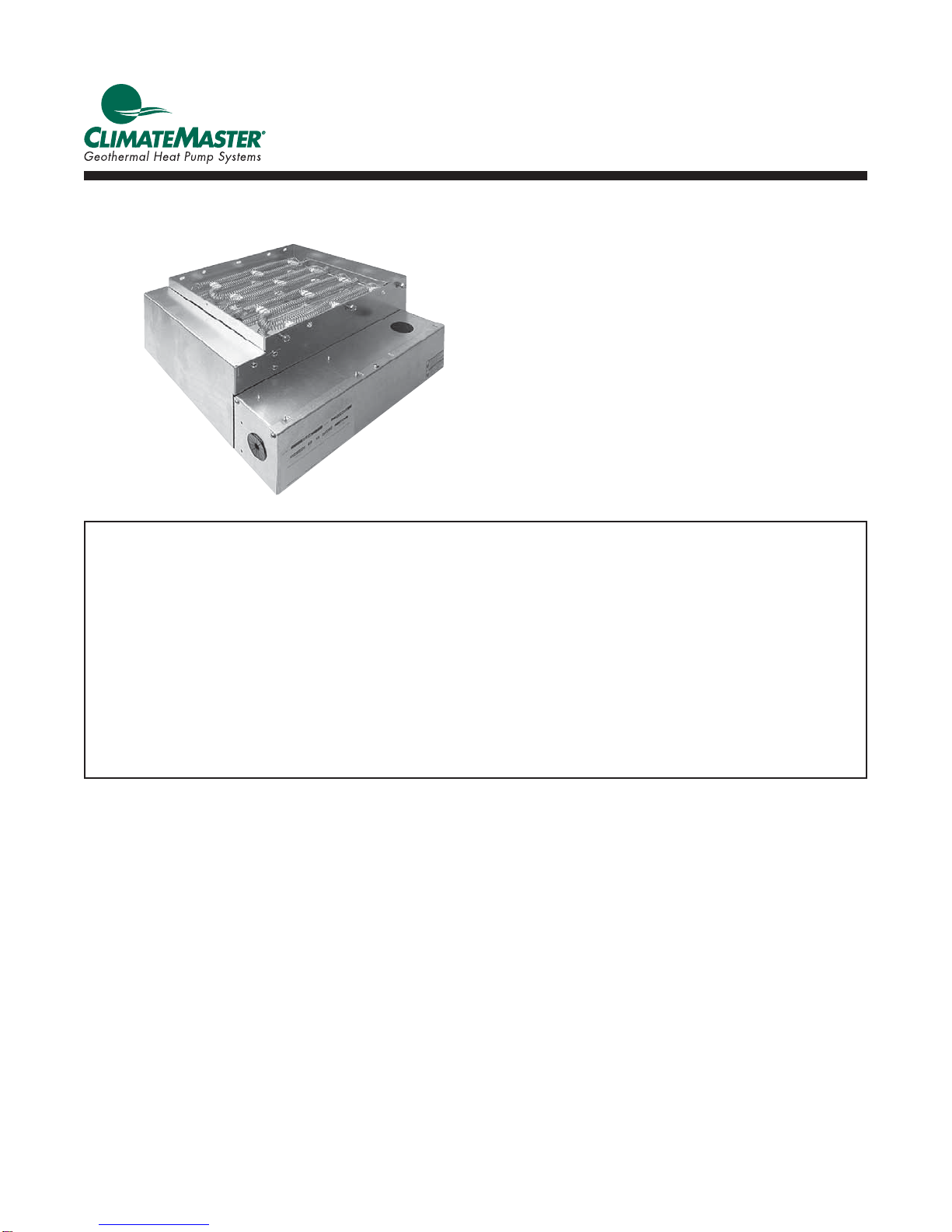
Auxiliary Electric Heat
Installation, Operation &
Maintenance Instructions
97B0005N02
Revision: 1/14/13
AG Series Electric Heaters
Table of Contents
Overview 3
Vertical Upflow or Downflow
Installation - Internal 3
Vertical Upflow Installation - External 4
Horizontal Installation - External
Wiring 6
Setup 6
Ratings 7
Electrical Data 7
Staging Options 7-8
Accessory Heater Dimensions 9
Warranty 10
Revision Log 12

This page was intentionally left blank.
3
Electric Heat - Installation, Operation, and Maintenance
Rev.: 14 Jan., 2013
Overview
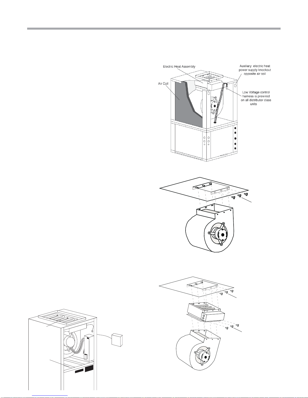
The AG Series Auxiliary Electric Heat mounts internally on
TS, TE and TT upflow (Figure 1b) or downflow units and all
TAH units. It mounts directly to the blower outlet of TS, TE
and TT horizontal units (Figure 8) and on all TZ units. Note
the model compatibility Table 1. Horizontal units are rated
for zero clearance at the unit and 1" clearance for first three
feet of duct, vertical units rated for zero clearance for both
unit and duct. Downflow units can not be located directly
over a discharge register. The discharge plenum must be
constructed from non combustible material. TheAG electric
heat contains a four stage relay control board which activates
the elements directly via an internally wired low voltage
harness. Low voltage signals (W1 and W2) are staged from
the CXM or DXM control of the unit.
TS ,TT and TE Vertical Upflow or Downflow and TAH
Installation - Internal
1. Disconnect power to the unit.
2. Remove blower access panel(s) from the unit and
control box cover from the electric heater.
3. Remove blower mounting bolts and drop blower
assembly as shown in figure 2. Removal of electrical
wiring should not be necessary.
4. Position the electric heater as illustrated in figure 3 with
its control box facing the front access panel of the unit.
Attach heater to unit using the support pins on the back
and bolts on the front.
The electric heater air inlet dimensions should match the
unit blower outlet, installer should stop and refer to the
unit/heater compatibility chart later in this instruction or
consult factory if they do not match.
5. Re-install blower assembly on to electric heater using
pins and bolts as before. Check blower electrical wiring
for proper connection and remedy any pinched wire(s) or
contact with sharp edges.
6. Route the low voltage control harness through one of the
‘pie’ bushings in the heater control box and plug on to
the P2 connector. See figure 6.
7. Install power conduit through the unit cabinet as shown
in figure 7 and attach directly to the electric heater
control box. See figures 9a-c.
8. Replace all covers and panels, heater installation is
complete. Proceed to wiring and setup.
5HPRYHEROWV
DQGGURSEORZHU
/RFDWHHOHFWULFKHDWDVVHPEO\
RQSLQVLQGLVFKDUJHSDQHO
DQGLQVHUWEROWV
5HORFDWHEORZHULQHOHFWULF
KHDWDVVHPEO\LQVDPH
PDQQHU
Figure 2: Blower removal
Figure 3: AG electric heat mounting and
blower re-installation
Figure 1b: Typical vertical unit installation
Overview
$LU&RLO
(OHFWULF+HDW
$VVHPEO\
)LHOGVXSSOLHG
GLVFRQQHFW
UHIHUWRORFDOFRGHV
/RZYROWDJHFRQWUROKDUQHVV
LVSUHZLUHGRQDOO
GLVWULEXWRUFODVVXQLWV
Figure 1a: Typical air handler installation

Electric Heat - Installation, Operation, and Maintenance
Rev.: 14 Jan., 2013
4Geothermal Heat Pump Systems
Vertical Installation - External
Auxiliary electric heat
power supply knockout
opposite air coil
Electric Heat Assembly
Air Coil
Low Voltage control harness
is prewired on all distributor
class units.
*
Figure 4: Typical Vertical External Mount Installation
TZ Vertical Upflow External Installation
1. Disconnect power to the unit.
2. Remove blower access panel(s) from the unit and control
box and element covers from the electric heater.
3. Locate remove and discard blower discharge flanges
from the unit but save the screws. Flanges will be
packaged loose inside the blower compartment of
vertical upflow units. TZ036 and 042 units require a
transition bracket between the cabinet top and the
electric heater. This bracket is packaged inside the
blower compartment for field installation.
4. Position the electric heater as illustrated herein. Heater
control box should be facing the front access panel of
vertical units.
The electric heater air inlet dimensions should match
the unit air outlet, installer should stop and refer to the
unit/heater compatibility chart later in this instruction or
consult factory if they do not match.
5. Use the saved blower flange screws to attach the heater
by its flanges to the unit panel except do not fasten
flange on control box side.
6. Use aluminum tape (not provided) to seal all four heater
flanges to the blower panel.
7. Locate and route the low voltage control harness through
the top panel knockout(s). Seal the penetration ‘air tight’.
This harness is factory installed on all TZ units (wire-tied
to the fan housing).
8. Route the control harness through one of the ‘pie’
bushings in the heater control box and plug on to the P2
connector. See figure 5.
9. Install power conduit and attach directly to the electric
heater control box. See figures 5a-c.
10. Replace all covers and panels, heater installation is
complete. Proceed to wiring and setup.
Figure 5: Power Conduit And Wire Routing
(internal mount)

5
Electric Heat - Installation, Operation, and Maintenance
Rev.: 14 Jan., 2013
Horizontal External Installation
1. Disconnect power to the unit.
2. Remove blower access panel from the unit and control box
and element covers from the electric heater.
3. Remove and discard blower discharge flanges from the
unit but save the screws. TZ036 and 042 units require
a transition bracket between the cabinet top and the
electric heater. This bracket is packaged inside the
blower compartment for field installation.
4. Position the electric heater as illustrated herein. Notice
that the discharge air opening is off centered in the
blower panel. The electric heater must be positioned so
that its control box is located vertically over the wide
side of this panel.
The electric heater air inlet dimensions should match
the unit air outlet, installer should stop and refer to the
unit/heater compatibility chart later in this instruction or
consult factory if they do not match.
5. Use the saved blower flange screws to attach the heater
by its flanges to the unit panel except do not fasten
flange on control box side.
6. Use aluminum tape (not provided) to seal all four heater
flanges to the blower panel.
7. Locate and route the low voltage control harness
through one of the unit corner post or blower panel
knockout(s). Seal the penetration ‘air tight’. This harness
is factory installed and wire-tied to the fan housing.
8. Route the control harness through one of the ‘pie’
bushings in the heater control box and plug on to the P2
connector. See figure 6.
9. Install power conduit and attach directly to the electric
heater control box.
10. Replace all covers and panels, heater installation is
complete. Proceed to wiring and setup.
Figure 6: Low Voltage Harness Connection
Figure 8: Typical Horizontal Installation
Horizontal Installation - External
Locate electric heat
harness in air handler
and route through
one of the provided
bushing
Field-supplied disconnect
(refer to local codes)

Electric Heat - Installation, Operation, and Maintenance
Rev.: 14 Jan., 2013
6Geothermal Heat Pump Systems
21
2))
21
2))
3
,QDQGN:XQLWV
WZRSRZHUFLUFXLWVDUH
HPSOR\HGWRUHGXFHZLUHV
VL]HDQGFRVWRIEUHDNHUV
/
/
/
/
3
&RQGXLW
Figure 8a: Power Wiring, Dual Circuits, 15, 20kw Figure 8b: Power Wiring, Single Circuit, 12, 15, 20kw
Wiring and Setup (all models)
1. Install power wiring and connect to power block or
circuit breakers. In 15 or 20kW models two power
circuits may be used to reduce wiring and breaker
costs as in Figure 8a. If a single circuit supply is
desired, install the optional single circuit accessory kit
(P/N 16B0002N02), as shown in Figure 8b, that can be
obtained from your distributor.
Optional for TAH: AG**C kits only. Blower power may
be supplied from T3 & T4 CB5 breaker. Refer to wiring
diagram 96B0143N01.
2.
Ensure unit airflow setting is above minimum airflow rating
for the electric heat model from Table 1.
3. Check staging jumpers for the application. Typically
only 5 kW (factory setting on all models except 10kW on
20kW models) is needed for first stage electric (W1) to
minimize electric demand. This staging can be adjusted
by moving the staging jumpers as shown in Figure 9.
Whatever is jumped to P1 pin 1 will be energized on
1st stage of electric heat, and P1-2 will be energized as
stage 2 electric heat. See Table 4 for staging options.
4. Mark the appropriate box of the electric heat model
installed on the additional serial plate on the exterior of
the unit.
5. Turn on the power to the unit and the auxiliary
electric heat.
Auxiliary Electric Heat Start-up
Put thermostat in emergency heat mode (or jumper t-stat
input R to W and R to G) and setpoint to high setting. ‘Touch-
jumper' the test pins of the CXM or DXM into test mode to
reduce time delays. Unit will require 15-20 seconds before
engaging emergency heat mode stage 1 (W1) and then
another 15-20 seconds to engage stage 2 (W2) when in ‘Test
mode’. Verify proper electric heat operation.
NO
Com ER1
NO
Com ER2
NO
Com ER3
NO
Com ER4
123
Tan
Ora
Factory Staging
(see Table 2)
Low Voltage Connector
(from Unit Control Board)
AG Electric Heat
Relay Board P1P2
24V
W1
W2
4
5kW (‘ER1’ 5kW & ‘ER4’ 0kW) and W2 (second stage)
will have 10kW (‘ER2 & 3’ 5kW each)
1234
Tan
Ora
P2
Side View as seen in Control Box
P1
Staging Example on a 15kW unit W1 (first stage) has
blank
Figure 9: Staging Jumpers
Figure 8c: Power Wiring, 4, 5, 8, and 10kw
Wiring
In 15 and 20 kW units, optional
single power circuit is employed to
reduce the number of wires needed.
Conduit
7
Electric Heat - Installation, Operation, and Maintenance
Rev.: 14 Jan., 2013
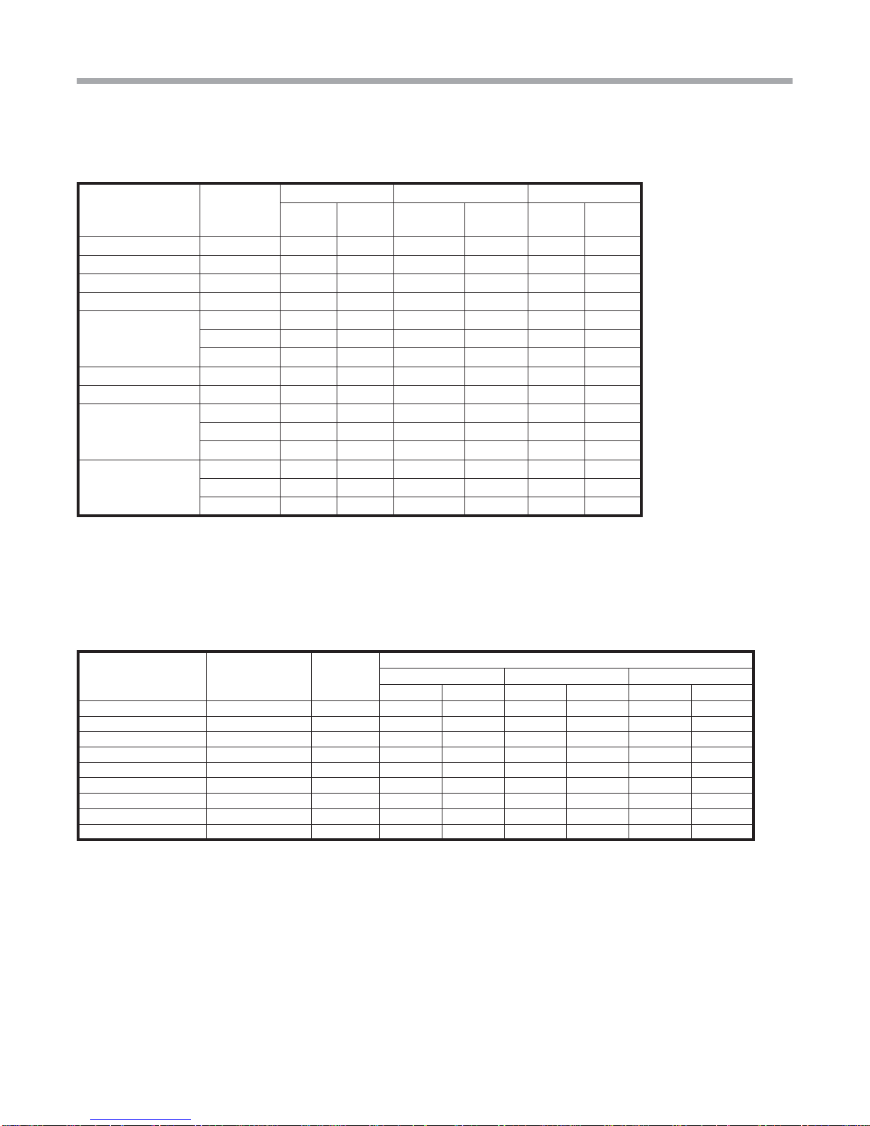
Table 2: AG Electric Heat Electrical Data - TAH
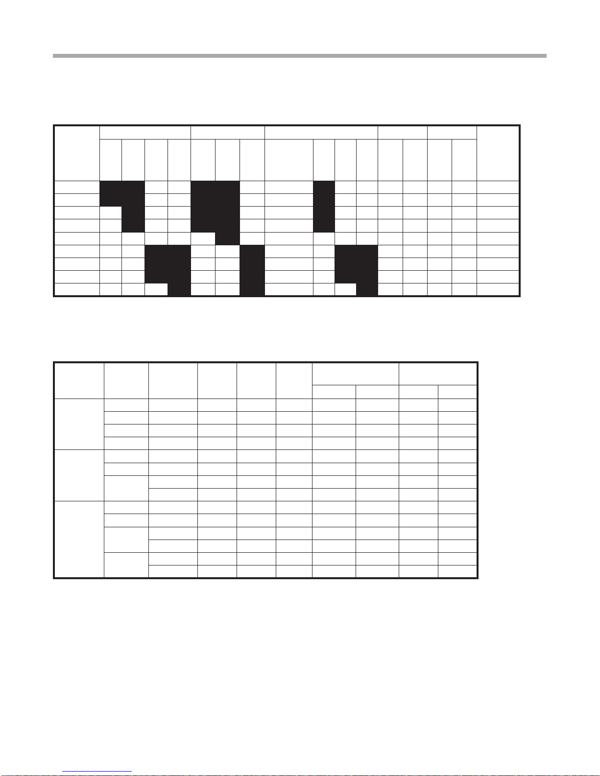
Table 1: AG Electric Heat Ratings
Staging Options
Auxiliary
Electric
Heat
Model
TS, TT, TE Models TZ Models TAH Models kW Rating Btuh Rating Minimum
CFM
Required
018 024-
030 036-
038 042-
072 024 030-
042 048-
060
Auxiliary
Electric
Heat
Model*
026 038 049-
064 240V 208V 240V 208V
AGM4A AGM4C 3.8 2.9 13000 9900 500
AGM5A AGM5C 4.8 3.6 16300 12300 500
AGM8A AGM8C 7.6 5.7 25900 19400 650
AGM10A AGM10C 9.6 7.2 32700 24600 650
AGM12A 11.4 8.6 38900 29200 750
AGL4A AGL4C 3.8 2.9 13000 9900 500
AGL10A AGL10C 9.6 7.2 32700 24600 1300
AGL15A AGL15C 14.4 10.8 49100 36900 1350
AGL20A AGL20C 19.2 14.4 65500 49200 1350
Black area denotes compatibility
Note: Horizontal units rated for zero clearance unit and 1” clearance for the first three feet of duct,
Vertical units rated for zero clearance for both unit and duct.
* Can be used on corresponding TZ, TE, TS and TT models
Unit Model Head Kit
Model Supply Heater
Amps
240
Heater
Amps
208
Blower
FLA Minimum Circuit Amps Maximum Breaker
Size
240 V 208 V 240 V 208 V
TAH026
AGM4C SINGLE 15.8 14 4.3 25 23 25 25
AGM 5C SINGLE 20 17.3 4.3 30 27 30 30
AGM 8C SINGLE 31.7 27.5 4.3 45 40 45 40
AGM 10C SINGLE 40 34.7 4.3 55 49 60 50
TAH038
AGL4C SINGLE 15.8 14 4.3 28.5 26.25 30 30
AGL10C SINGLE 40 34.7 4.3 59 52 60 60
AGL15C DUAL L1/L2 40 34.7 0 50 43 50 45
L3/L4 20 17.3 4.3 34 30 35 30
TAH049 and
TAH060
AGL4C SINGLE 15.8 14 7 28.5 26.25 30 30
AGL10C SINGLE 40 34.7 7.0 59 52 60 60
AGL15C DUAL L1/L2 40 34.7 0.0 50 43 50 45
L3/L4 20 17.3 7.0 34 30 35 30
AGL20C DUAL L1/L2 40 34.7 0.0 50 43 50 45
L3/L4 40 34.7 7.0 59 52 60 60
All heaters rated single phase 208-240V 60Hz All Fuses UL Class K general purpose
All models 15kW or larger feature internal circuit breakers
Electric Heat - Installation, Operation, and Maintenance
Rev.: 14 Jan., 2013
8Geothermal Heat Pump Systems
Table 4: AG Electric Heat Staging Options
Auxiliary Electric
Heat Model Staging
Options Factory
Settings
Stage 1
Staging in kW
Jumper 1-4, 2-3† Jumper 1-3, 2-4† Jumper 1-2-3
Stage 1 Stage 2 Stage 1 Stage 2 Stage 1 Stage 2
AGM4A or C 4 4 4 0 4 0 4 0
AGM5A or C 5 5 5 0 5 0 5 0
AGM8A or C 4 or 8 4 4 4 4 4 8 0
AGM10A or C 5 or 10 5 5 5 5 5 10 0
AGM12A or C 4, 8 or 12 4 4 8 8 4 12 0
AGL4A or C 4 4 4 0 4 0 4 0
AGL10A or C 5 or 10 5 5 5 5 5 10 0
AGL15A or C 5, 10 or 15 5 5 10 10 5 15 0
AGL20A or C 5, 10, 15 or 20 10 10 10 10 10 15 5
† Factory jumper setting
Auxiliary Electric
Heat Model Supply
Circuit
Heater Amps Minimum Circuit Amps Maximum Fuse
240V 208V 240V 208V 240V 208V
AGM4A Single 15.8 14.0 19.8 17.1 20 20
AGM5A Single 20.0 17.3 25.0 21.6 25 25
AGM8A Single 31.7 27.5 39.6 34.4 40 35
AGM10A Single 40.0 34.7 50.0 43.4 50 45
AGM12A
Single 47.5 41.2 59.4 51.5 60 60
Dual - L1/L2 31.7 27.5 39.6 34.4 40 35
Dual - L3/L4 15.8 13.7 19.8 17.1 20 20
AGL4A Single 15.8 14.0 19.8 17.1 20 20
AGL10A Single 40.0 34.7 50.0 43.4 50 45
AGL15A
Single 60.0 52.0 75.0 65.0 80 70
Dual - L1/L2 40.0 34.7 50.0 43.4 50 45
Dual - L3/L4 20.0 17.3 25.0 21.6 25 25
AGL20A
Single 80.0 69.3 100.0 86.6 100 90
Dual - L1/L2 40.0 34.7 50.0 43.4 50 45
Dual - L3/L4 40.0 34.7 50.0 43.4 50 45
All heaters rated single phase 208-240V 60Hz All Fuses UL Class K general purpose
All models 15kW or larger feature internal circuit breakers
Table 3: AG Electric Heat Electrical Data - TS/TT/TE
Staging Options
9
Electric Heat - Installation, Operation, and Maintenance
Rev.: 14 Jan., 2013
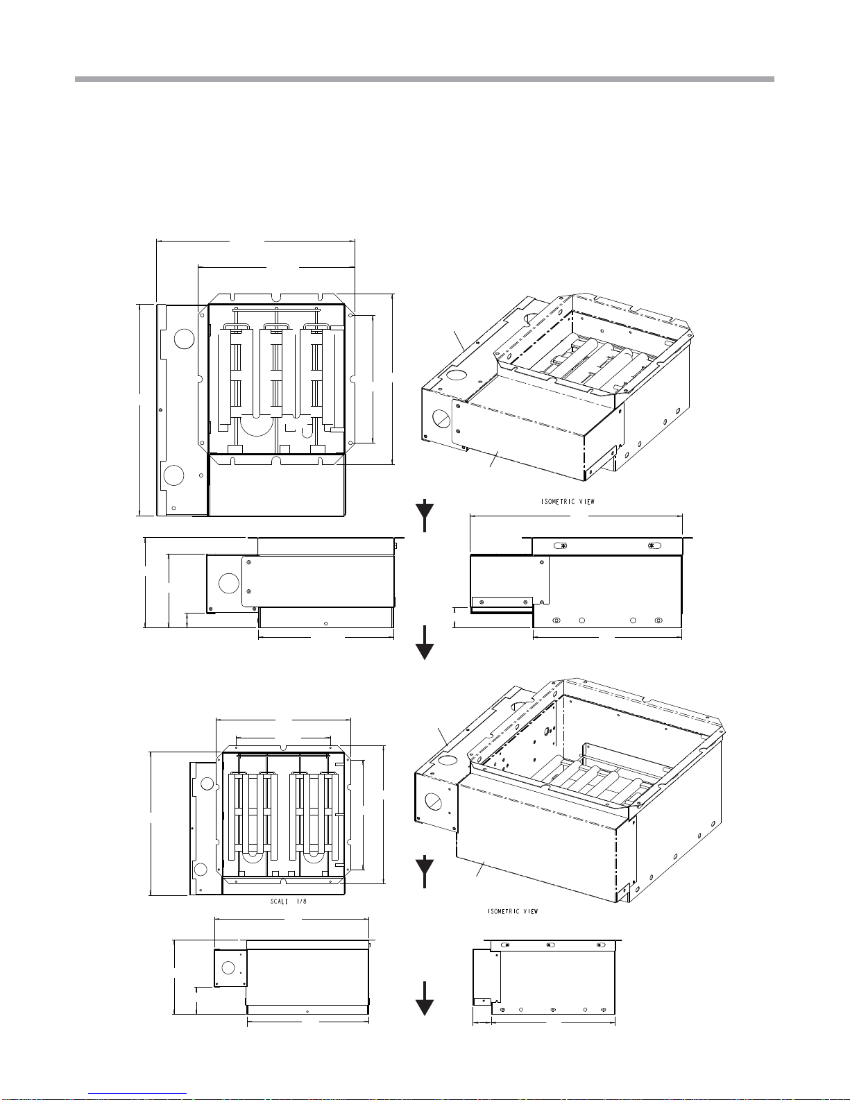
Accessory Heater Dimensions
Figure 10: Heater Dimensions
NOTE: The maximum recommended air velocity for a supply plenum is 900 fpm. When connecting a plenum to an
external supplemental heater, ensure that the air velocity in the plenum does not exceed 900 fpm. Noise and air
distribution issues may occur if supply plenum velocities exceed 900 fpm.
AGM4A - 12A
AGL4A - 20A
14.7
Control box
Element
cover
10.3
15.5
15.1
12
Discharge Air Opening Discharge Air Opening
16.8
8.1
3
13.3 13.5
2
A
I
R
F
L
O
W
Discharge Air Opening Discharge Air Opening
A
I
R
F
L
O
W
Rev. A 13.6
Rev. B 14.9
Rev. A 10.7
Rev. B 12.0
14.6
8.8
11.7
Control box
Element
cover
13.6
10.7
6.2
5.1
Rev. A 9.4
Rev. B 10.6
10.2
1
14.6
1.4
9.4
Electric Heat - Installation, Operation, and Maintenance
Rev.: 14 Jan., 2013
10 Geothermal Heat Pump Systems
&/,0$7(0$67(5,1&
/,0,7('(;35(66:$55$17</,0,7$7,212)5(0(',(6$1'/,$%,/,7<)25
5(6,'(17,$/&/$66352'8&76:,7+/$%25$//2:$1&(
,WLVH[SUHVVO\XQGHUVWRRGWKDWXQOHVVDVWDWHPHQWLVVSHFL¿FDOO\LGHQWL¿HGDVDZDUUDQW\VWDWHPHQWVPDGHE\&OLPDWH0DVWHU,QFD'HODZDUHFRUSRUDWLRQ³&0´RULWVUHSUHVHQWDWLYHVUHODWLQJWR&0¶VSURGXFWVZKHWKHURUDOZULWWHQRUFRQWDLQHG
LQDQ\VDOHVOLWHUDWXUHFDWDORJRUDJUHHPHQWDUHQRWH[SUHVVZDUUDQWLHVDQGGRQRWIRUPDSDUWRIWKHEDVLVRIWKHEDUJDLQEXWDUHPHUHO\&0¶VRSLQLRQRUFRPPHQGDWLRQRI&0¶VSURGXFWV(;&(37$663(&,),&$//<6(7)257+
+(5(,17+(5(,612(;35(66:$55$17<$672$1<2)&0¶6352'8&76&00$.(612:$55$17<$*$,167/$7(17'()(&76&00$.(612:$55$17<2)0(5&+$17$%,/,7<2)7+(
*22'6252)7+(),71(662)7+(*22'6)25$1<3$57,&8/$5385326(
*5$172)/,0,7('(;35(66:$55$17<
&0ZDUUDQWVLWV5HVLGHQWLDO&ODVVSURGXFWVSXUFKDVHGDQGUHWDLQHGLQWKH8QLWHG6WDWHVRI$PHULFDDQG&DQDGDWREHIUHHIURPGHIHFWVLQPDWHULDODQGZRUNPDQVKLSXQGHUQRUPDOXVHDQGPDLQWHQDQFHDVIROORZV$LUFRQGLWLRQLQJKHDWLQJ
DQGRUKHDWSXPSXQLWVEXLOWRUVROGE\&0³&08QLWV´IRUWHQ\HDUVIURPWKH:DUUDQW\,QFHSWLRQ'DWHDVGH¿QHGEHORZ7KHUPRVWDWVDX[LOLDU\HOHFWULFKHDWHUVDQGJHRWKHUPDOSXPSLQJPRGXOHVEXLOWRUVROGE\&0ZKHQLQVWDOOHG
ZLWK&08QLWVIRUWHQ\HDUVIURPWKH:DUUDQW\,QFHSWLRQ'DWHDVGH¿QHGEHORZDQG2WKHUDFFHVVRULHVDQGSDUWVEXLOWRUVROGE\&0ZKHQLQVWDOOHGZLWK&08QLWVIRURQH\HDUIURPWKHGDWHRIVKLSPHQWIURP&07KH³:DUUDQW\
,QFHSWLRQ'DWH´VKDOOEHWKHGDWHRIRULJLQDOXQLWLQVWDOODWLRQRUVL[PRQWKVIURPGDWHRIXQLWVKLSPHQWIURP&0ZKLFKHYHUFRPHV¿UVW
7RPDNHDFODLPXQGHUWKLVZDUUDQW\SDUWVPXVWEHUHWXUQHGWR&0LQ2NODKRPD&LW\2NODKRPDIUHLJKWSUHSDLGQRODWHUWKDQQLQHW\GD\VDIWHUWKHGDWHRIWKHIDLOXUHRIWKHSDUWLI&0GHWHUPLQHVWKHSDUWWREHGHIHFWLYHDQGZLWKLQ&0¶V
/LPLWHG([SUHVV:DUUDQW\&0VKDOOZKHQVXFKSDUWKDVEHHQHLWKHUUHSODFHGRUUHSDLUHGUHWXUQVXFKWRDIDFWRU\UHFRJQL]HGGLVWULEXWRUGHDOHURUVHUYLFHRUJDQL]DWLRQ)2%&02NODKRPD&LW\2NODKRPDIUHLJKWSUHSDLG7KHZDUUDQW\RQ
DQ\SDUWUHSDLUHGRUUHSODFHGXQGHUZDUUDQW\H[SLUHVDWWKHHQGRIWKHRULJLQDOZDUUDQW\SHULRG
7KLV/LPLWHG([SUHVV:DUUDQW\VKDOOFRYHUWKHODERULQFXUUHGE\&0DXWKRUL]HGVHUYLFHSHUVRQQHOLQFRQQHFWLRQZLWKWKHLQVWDOODWLRQRIDQHZRUUHSDLUHGZDUUDQW\SDUWWKDWLVFRYHUHGE\WKLV/LPLWHG([SUHVV:DUUDQW\RQO\WRWKHH[WHQW
VSHFL¿FDOO\VHWIRUWKLQWKHWKHQH[LVWLQJODERUDOORZDQFHVFKHGXOHSURYLGHGE\&0¶V:DUUDQW\'HSDUWPHQWDQGRQO\DVIROORZV&08QLWVIRU¿YH\HDUVIURPWKH:DUUDQW\,QFHSWLRQ'DWH7KHUPRVWDWVDX[LOLDU\HOHFWULFKHDWHUVDQG
JHRWKHUPDOSXPSLQJPRGXOHVEXLOWRUVROGE\&0ZKHQLQVWDOOHGZLWK&08QLWVIRU¿YH\HDUVIURPWKH:DUUDQW\,QFHSWLRQ'DWH$FWXDO/DERUFRVWVDUHQRWFRYHUHGE\WKLV/LPLWHG([SUHVV:DUUDQW\WRWKHH[WHQWWKH\H[FHHGWKHDPRXQW
DOORZHGXQGHUVDLGDOORZDQFHVFKHGXOHWKH\DUHQRWVSHFL¿FDOO\SURYLGHGIRULQVDLGDOORZDQFHVFKHGXOHWKH\DUHQRWWKHUHVXOWRIZRUNSHUIRUPHGE\&0DXWKRUL]HGVHUYLFHSHUVRQQHOWKH\DUHLQFXUUHGLQFRQQHFWLRQZLWKDSDUWQRWFRYHUHGE\
WKLV/LPLWHG([SUHVV:DUUDQW\RUWKH\DUHLQFXUUHGPRUHWKDQWKHWLPHSHULRGVVHWIRUWKLQWKLVSDUDJUDSKDIWHUWKH:DUUDQW\,QFHSWLRQ'DWH
7KLVZDUUDQW\GRHVQRWFRYHUDQGGRHVQRWDSSO\WR$LU¿OWHUVIXVHVUHIULJHUDQWÀXLGVRLO3URGXFWVUHORFDWHGDIWHULQLWLDOLQVWDOODWLRQ$Q\SRUWLRQRUFRPSRQHQWRIDQ\V\VWHPWKDWLVQRWVXSSOLHGE\&0UHJDUGOHVVRIWKHFDXVHRIWKH
IDLOXUHRIVXFKSRUWLRQRUFRPSRQHQW3URGXFWVRQZKLFKWKHXQLWLGHQWL¿FDWLRQWDJVRUODEHOVKDYHEHHQUHPRYHGRUGHIDFHG3URGXFWVRQZKLFKSD\PHQWWR&0RUWRWKHRZQHU¶VVHOOHURULQVWDOOLQJFRQWUDFWRULVLQGHIDXOW3URGXFWV
VXEMHFWHGWRLPSURSHURULQDGHTXDWHLQVWDOODWLRQPDLQWHQDQFHUHSDLUZLULQJRUYROWDJHFRQGLWLRQV3URGXFWVVXEMHFWHGWRDFFLGHQWPLVXVHQHJOLJHQFHDEXVH¿UHÀRRGOLJKWQLQJXQDXWKRUL]HGDOWHUDWLRQPLVDSSOLFDWLRQFRQWDPLQDWHG
RUFRUURVLYHDLURUOLTXLGVXSSO\RSHUDWLRQDWDEQRUPDODLURUOLTXLGWHPSHUDWXUHVRUÀRZUDWHVRURSHQLQJRIWKHUHIULJHUDQWFLUFXLWE\XQTXDOL¿HGSHUVRQQHO0ROGIXQJXVRUEDFWHULDGDPDJHV&RUURVLRQRUDEUDVLRQRIWKHSURGXFW
3URGXFWVVXSSOLHGE\RWKHUV3URGXFWVZKLFKKDYHEHHQRSHUDWHGLQDPDQQHUFRQWUDU\WR&0¶VSULQWHGLQVWUXFWLRQV3URGXFWVZKLFKKDYHLQVXI¿FLHQWSHUIRUPDQFHDVDUHVXOWRILPSURSHUV\VWHPGHVLJQRULPSURSHUDSSOLFDWLRQ
LQVWDOODWLRQRUXVHRI&0¶VSURGXFWVRU(OHFWULFLW\RUIXHOFRVWVRUDQ\LQFUHDVHVRUXQUHDOL]HGVDYLQJVLQVDPHIRUDQ\UHDVRQZKDWVRHYHU
7KLV/LPLWHG([SUHVV:DUUDQW\SURYLGHVWKHOLPLWHGODERUDOORZDQFHFRYHUDJHDVVHWIRUWKDERYH2WKHUZLVH&0LVQRWUHVSRQVLEOHIRU7KHFRVWVRIDQ\ÀXLGVUHIULJHUDQWRUV\VWHPFRPSRQHQWVVXSSOLHGE\RWKHUVRUDVVRFLDWHGODERUWRUHSDLU
RUUHSODFHWKHVDPHZKLFKLVLQFXUUHGDVDUHVXOWRIDGHIHFWLYHSDUWFRYHUHGE\&0¶V/LPLWHG([SUHVV:DUUDQW\7KHFRVWVRIODERUUHIULJHUDQWPDWHULDOVRUVHUYLFHLQFXUUHGLQGLDJQRVLVDQGUHPRYDORIWKHGHIHFWLYHSDUWRULQREWDLQLQJDQG
UHSODFLQJWKHQHZRUUHSDLUHGSDUW7UDQVSRUWDWLRQFRVWVRIWKHGHIHFWLYHSDUWIURPWKHLQVWDOODWLRQVLWHWR&0RURIWKHUHWXUQRIWKDWSDUWLIQRWFRYHUHGE\&0¶V/LPLWHG([SUHVV:DUUDQW\RU7KHFRVWVRIQRUPDOPDLQWHQDQFH
7KLV/LPLWHG([SUHVV:DUUDQW\DSSOLHVWR&05HVLGHQWLDO&ODVVSURGXFWVRUGHUHGIURP&0RQRUDIWHU0D\WKLVZRXOGJHQHUDOO\LQFOXGH&08QLWVZLWKVHULDOQXPEHUVEHJLQQLQJZLWK³1´DQGKLJKHUDQGLVQRWUHWURDFWLYHWRDQ\
SURGXFWVRUGHUHGIURP&0SULRUWR0D\WKLVZRXOGJHQHUDOO\LQFOXGH&08QLWVZLWKVHULDOQXPEHUVEHJLQQLQJZLWK³1´DQGORZHU,I\RXDUHXQVXUHLIWKLV/LPLWHG([SUHVV:DUUDQW\DSSOLHVWRWKHSURGXFW\RXKDYHSXUFKDVHG
FRQWDFW&0DWWKHSKRQHQXPEHURUDGGUHVVUHÀHFWHGEHORZ
/LPLWDWLRQ7KLV/LPLWHG([SUHVV:DUUDQW\LVJLYHQLQOLHXRIDOORWKHUZDUUDQWLHV,IQRWZLWKVWDQGLQJWKHGLVFODLPHUVFRQWDLQHGKHUHLQLWLVGHWHUPLQHGWKDWRWKHUZDUUDQWLHVH[LVWDQ\VXFKH[SUHVVZDUUDQW\LQFOXGLQJZLWKRXWOLPLWDWLRQDQ\
H[SUHVVZDUUDQWLHVRUDQ\LPSOLHGZDUUDQWLHVRI¿WQHVVIRUSDUWLFXODUSXUSRVHDQGPHUFKDQWDELOLW\VKDOOEHOLPLWHGWRWKHGXUDWLRQRIWKH/LPLWHG([SUHVV:DUUDQW\
/,0,7$7,212)5(0(',(6
,QWKHHYHQWRIDEUHDFKRIWKH/LPLWHG([SUHVV:DUUDQW\&0ZLOORQO\EHREOLJDWHGDW&0¶VRSWLRQWRUHSDLUWKHIDLOHGSDUWRUXQLWRUWRIXUQLVKDQHZRUUHEXLOWSDUWRUXQLWLQH[FKDQJHIRUWKHSDUWRUXQLWZKLFKKDVIDLOHG,IDIWHUZULWWHQQRWLFH
WR&0¶VIDFWRU\LQ2NODKRPD&LW\2NODKRPDRIHDFKGHIHFWPDOIXQFWLRQRURWKHUIDLOXUHDQGDUHDVRQDEOHQXPEHURIDWWHPSWVE\&0WRFRUUHFWWKHGHIHFWPDOIXQFWLRQRURWKHUIDLOXUHDQGWKHUHPHG\IDLOVRILWVHVVHQWLDOSXUSRVH&0VKDOO
UHIXQGWKHSXUFKDVHSULFHSDLGWR&0LQH[FKDQJHIRUWKHUHWXUQRIWKHVROGJRRGV6DLGUHIXQGVKDOOEHWKHPD[LPXPOLDELOLW\RI&07+,65(0('<,67+(62/($1'(;&/86,9(5(0('<2)7+(%8<(525385&+$6(5
$*$,167&0)25%5($&+2)&2175$&7)257+(%5($&+2)$1<:$55$17<25)25&0¶61(*/,*(1&(25,1675,&7/,$%,/,7<
/,0,7$7,212)/,$%,/,7<
&0VKDOOKDYHQROLDELOLW\IRUDQ\GDPDJHVLI&0¶VSHUIRUPDQFHLVGHOD\HGIRUDQ\UHDVRQRULVSUHYHQWHGWRDQ\H[WHQWE\DQ\HYHQWVXFKDVEXWQRWOLPLWHGWRDQ\ZDUFLYLOXQUHVWJRYHUQPHQWUHVWULFWLRQVRUUHVWUDLQWVVWULNHVRU
ZRUNVWRSSDJHV¿UHÀRRGDFFLGHQWVKRUWDJHVRIWUDQVSRUWDWLRQIXHOPDWHULDORUODERUDFWVRI*RGRUDQ\RWKHUUHDVRQEH\RQGWKHVROHFRQWURORI&0&0(;35(66/<',6&/$,06$1'(;&/8'(6$1</,$%,/,7<)25
&216(48(17,$/25,1&,'(17$/'$0$*(,1&2175$&7)25%5($&+2)$1<(;35(6625,03/,(':$55$17<25,17257:+(7+(5)25&0¶V1(*/,*(1&(25$6675,&7/,$%,/,7<
2%7$,1,1*:$55$17<3(5)250$1&(
1RUPDOO\WKHGHDOHURUVHUYLFHRUJDQL]DWLRQZKRLQVWDOOHGWKHSURGXFWVZLOOSURYLGHZDUUDQW\SHUIRUPDQFHIRUWKHRZQHU6KRXOGWKHLQVWDOOHUEHXQDYDLODEOHFRQWDFWDQ\&0UHFRJQL]HGGLVWULEXWRUGHDOHURUVHUYLFHRUJDQL]DWLRQ,IDVVLVWDQFHLV
UHTXLUHGLQREWDLQLQJZDUUDQW\SHUIRUPDQFHZULWHRUFDOO
&OLPDWH0DVWHU,QF&XVWRPHU6HUYLFH6:WK6WUHHW2NODKRPD&LW\2NODKRPDHVHUYLFH#FOLPDWHPDVWHUFRP
127(6RPHVWDWHVRU&DQDGLDQSURYLQFHVGRQRWDOORZOLPLWDWLRQVRQKRZORQJDQLPSOLHGZDUUDQW\ODVWVRUWKHOLPLWDWLRQRUH[FOXVLRQVRIFRQVHTXHQWLDORULQFLGHQWDOGDPDJHVVRWKHIRUHJRLQJH[FOXVLRQVDQGOLPLWDWLRQVPD\QRWDSSO\WR\RX
7KLVZDUUDQW\JLYHV\RXVSHFL¿FOHJDOULJKWVDQG\RXPD\DOVRKDYHRWKHUULJKWVZKLFKYDU\IURPVWDWHWRVWDWHDQGIURP&DQDGLDQSURYLQFHWR&DQDGLDQSURYLQFH
3OHDVHUHIHUWRWKH&0,QVWDOODWLRQ2SHUDWLRQDQG0DLQWHQDQFH0DQXDOIRURSHUDWLQJDQGPDLQWHQDQFHLQVWUXFWLRQV 5HY
3DUW1R53
Warranty

11
Electric Heat - Installation, Operation, and Maintenance
Rev.: 14 Jan., 2013
Electric Heat - Installation, Operation, and Maintenance
Rev.: 14 Jan., 2013
12 Geothermal Heat Pump Systems
Revision History
R
M
A
N
U
F
A
C
T
U
R
E
R
C
E
R
T
I
F
I
E
D
T
O
A
R
I
A
S
C
O
M
P
L
Y
I
N
G
W
I
T
H
I
S
O
S
T
A
N
D
A
R
D
1
3
2
5
6
-
1
H
E
A
T
P
U
M
P
S
W
A
T
E
R
T
O
A
I
R
B
R
I
N
E
T
O
A
I
R
97B0005N02
ClimateMaster works continually to improve its products. As a result, the design and specifications of each product at the time for order may be
changed without notice and may not be as described herein. Please contact ClimateMaster’s Customer Service Department at 1-405-745-6000
for specific information on the current design and specifications. Statements and other information contained herein are not express warran-
ties and do not form the basis of any bargain between the parties, but are merely ClimateMaster’s opinion or commendation of its products.
The management system governing the manufacture of ClimateMaster’s products is ISO 9001:2008 certified.
© ClimateMaster, Inc. 2007
*97B0005N02*
7300 S.W. 44th Street
Oklahoma City, OK 73179
Phone: 405-745-6000
Fax: 405-745-6058
climatemaster.com
Rev.: 14 Dec., 2013
ISO 9001:2008
Certified
Quality: First & Always
Date Page # Description
14 Jan., 13 4-5 Installation Instructions Updated
14 Dec., 12 3, 4 Update TZ Text
8 May, 12 Various Added TE Mentions
25 Jan. 11 8 Dual Supply Circuit Updated
2 Nov. 11 Various TZ (Vertical External Install) Information Added
24 Sept, 10 8 Accessory Heater Dimension Information Added
20 July, 10 All Update Text, Add TAH and Size 4, Remove Size 12
24 June, 10 All Update Text,Add Size 4 Heater
05 June, 08 All Reformatted Document Size
03 Mar, 08 Various Various Minor Corrections
04 Mar, 07 6 Updated Table 1 for TT072 Models
01 Oct, 06 All First Published
Other manuals for AG Series
2
This manual suits for next models
9
Table of contents
Other ClimateMaster Electric Heater manuals


Popular Electric Heater manuals by other brands


Qlima
Qlima EOR 1515 LCD operating manual

Rointe
Rointe Giza OVAL 400 instruction & installation guide

DeLonghi
DeLonghi Electric oil filled heater instructions

Honeywell
Honeywell HZ-2302 - Electric Space Heater owner's manual

Sunbeam
Sunbeam Calefactor SEH402 instruction manual

ALPATEC
ALPATEC RBH 15 user manual

Reina
Reina MAIA instruction manual

Dyna-Glo
Dyna-Glo WHF100 Important instructions

NuTone
NuTone 665RP instruction manual

Roberts Gorden
Roberts Gorden Blackheat BH15UT Installation & servicing instructions

Paulin
Paulin 7500 Owner's manual & operating instructions

DeLonghi
DeLonghi ELECTRIC SUPER PANEL HEATER instruction manual