ClimateMaster AG Series General instructions
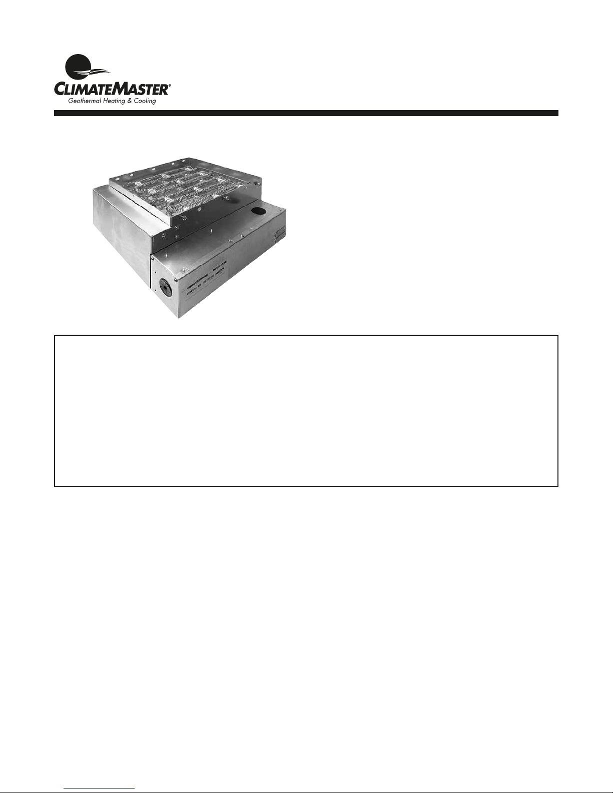
Auxiliary Electric Heat
Installation, Operation &
Maintenance Instructions
97B0005N04
Revised: 04 August, 2015
AG Series Electric Heaters
Table of Contents
Overview 3
Vertical Upow or Downow
Installation - Internal 3
Vertical Upow Installation - External 4
Horizontal Installation - External
Wiring 6
Setup 6
Ratings 7
Electrical Data 7
Staging Options 7-8
Accessory Heater Dimensions 9
Warranty 10
Revision Log 12

This page was intentionally left blank.
3
Electric Heat - Installation, Operation, and Maintenance
Revised: 04 August, 2015
climatemaster.com
Overview
The AG Series Auxiliary Electric Heat mounts internally on
TS, TE and TT upow (Figure 1b) or downow units and all
TAH units. It mounts directly to the blower outlet of TS, TE
and TT horizontal units (Figure 8) and on all TZ units. Note
the model compatibility Table 1. Horizontal units are rated
for zero clearance at the unit and 1" clearance for rst three
feet of duct, vertical units rated for zero clearance for both
unit and duct. Downow units can not be located directly
over a discharge register. The discharge plenum must be
constructed from non combustible material. The AG electric
heat contains a four stage relay control board which activates
the elements directly via an internally wired low voltage
harness. Low voltage signals (W1 and W2) are staged from
the CXM or DXM control of the unit.
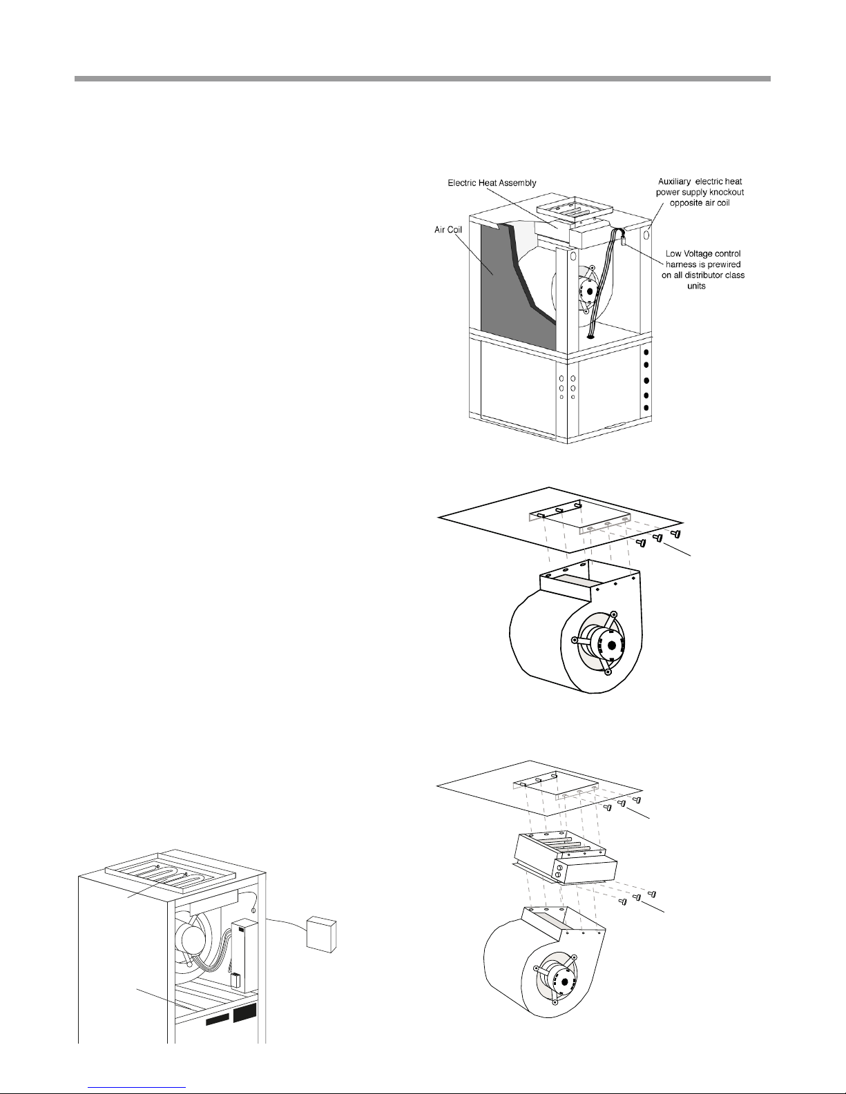
TS ,TT and TE Vertical Upow or Downow and TAH
Installation - Internal
1. Disconnect power to the unit.
2. Remove blower access panel(s) from the unit and
control box cover from the electric heater.
3. Remove blower mounting bolts and drop blower
assembly as shown in gure 2. Removal of electrical
wiring should not be necessary.
4. Position the electric heater as illustrated in gure 3 with
its control box facing the front access panel of the unit.
Attach heater to unit using the support pins on the back
and bolts on the front.
The electric heater air inlet dimensions should match the
unit blower outlet, installer should stop and refer to the
unit/heater compatibility chart later in this instruction or
consult factory if they do not match.
5. Re-install blower assembly on to electric heater using
pins and bolts as before. Check blower electrical wiring
for proper connection and remedy any pinched wire(s) or
contact with sharp edges.
6. Route the low voltage control harness through one of the
‘pie’ bushings in the heater control box and plug on to
the P2 connector. See gure 6.
7. Install power conduit through the unit cabinet as shown
in gure 7 and attach directly to the electric heater
control box. See gures 9a-c.
8. Replace all covers and panels, heater installation is
complete. Proceed to wiring and setup.
Remove bolts
and drop blower
Locate electric heat assembly
on pins in discharge panel
and insert bolts
Relocate blower in electric
heat assembly in same
manner
Figure 2: Blower removal
Figure 3: AG electric heat mounting and
blower re-installation
Figure 1b: Typical vertical unit installation
Overview
Air Coil
Electric Heat
Assembly
Field-supplied
disconnect
(refer to local codes)
Low voltage control harness
is prewired on all
distributor class units
Figure 1a: Typical air handler installation
Electric Heat - Installation, Operation, and Maintenance
Revised: 04 August, 2015
4ClimateMaster Geothermal Heating and Cooling
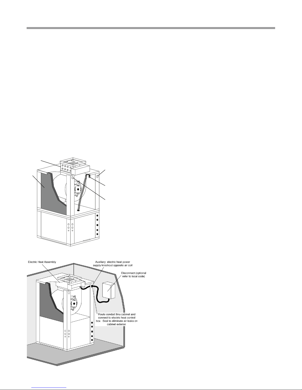
Vertical Installation - External
Auxiliary electric heat
power supply knockout
opposite air coil
Electric Heat Assembly
Air Coil
Low Voltage control harness
is prewired on all distributor
class units.
*
1. Disconnect power to the unit.
2. Remove blower access panel(s) from the unit and control
box and element covers from the electric heater.
3. Locate remove and discard blower discharge anges
from the unit but save the screws. Flanges will be
packaged loose inside the blower compartment of
vertical upow units. TZ036 and 042 units require a
transition bracket between the cabinet top and the
electric heater. This bracket is packaged inside the
blower compartment for eld installation.
4. Position the electric heater as illustrated herein. Heater
control box should be facing the front access panel of
vertical units.
The electric heater air inlet dimensions should match
the unit air outlet, installer should stop and refer to the
unit/heater compatibility chart later in this instruction or
consult factory if they do not match.
5. Use the saved blower ange screws to attach the heater
by its anges to the unit panel except do not fasten
ange on control box side.
6. Use aluminum tape (not provided) to seal all four heater
anges to the blower panel.
7. Locate and route the low voltage control harness through
the top panel knockout(s). Seal the penetration ‘air tight’.
This harness is factory installed on all TZ units (wire-tied
to the fan housing).
8. Route the control harness through one of the ‘pie’
bushings in the heater control box and plug on to the P2
connector. See gure 5.
9. Install power conduit and attach directly to the electric
heater control box. See gures 5a-c.
10. Replace all covers and panels, heater installation is
complete. Proceed to wiring and setup.

5
Electric Heat - Installation, Operation, and Maintenance
Revised: 04 August, 2015
climatemaster.com
Horizontal External Installation
1. Disconnect power to the unit.
2. Remove blower access panel from the unit and control box
and element covers from the electric heater.
3. Remove and discard blower discharge anges from the
unit but save the screws. TZ036 and 042 units require
a transition bracket between the cabinet panel and
the electric heater. This bracket is packaged inside the
blower compartment for eld installation.
4. Position the electric heater as illustrated herein. Notice
that the discharge air opening is o centered in the
blower panel. The electric heater must be positioned so
that its control box is located vertically over the wide
side of this panel.
The electric heater air inlet dimensions should match
the unit air outlet, installer should stop and refer to the
unit/heater compatibility chart later in this instruction or
consult factory if they do not match.
5. Use the saved blower ange screws to attach the heater
by its anges to the unit panel except do not fasten
ange on control box side.
6. Use aluminum tape (not provided) to seal all four heater
anges to the blower panel.
7. Locate and route the low voltage control harness
through one of the unit corner post or blower panel
knockout(s). Seal the penetration ‘air tight’. This harness
is factory installed and wire-tied to the fan housing.
8. Route the control harness through one of the ‘pie’
bushings in the heater control box and plug on to the P2
connector. See gure 6.
9. Install power conduit and attach directly to the electric
heater control box.
10. Replace all covers and panels, heater installation is
complete. Proceed to wiring and setup.
Figure 6: Low Voltage Harness Connection
Figure 8: Typical Horizontal Installation
Horizontal Installation - External
Locate electric heat
harness in air handler
and route through
one of the provided
bushing
Field-supplied disconnect
(refer to local codes)

Electric Heat - Installation, Operation, and Maintenance
Revised: 04 August, 2015
6ClimateMaster Geothermal Heating and Cooling
ON
OFF
ON
OFF
1234
P1
In 15 and 20 kW units
two power circuits are
employed to reduce wires
size and cost of breakers
L1
L2
L3
L4
P2
Conduit
Figure 8a: Power Wiring, Dual Circuits, 15, 20kw Figure 8b: Power Wiring, Single Circuit, 12, 15, 20kw
Wiring and Setup (all models)
1. Install power wiring and connect to power block or
circuit breakers. In 15 or 20kW models two power
circuits may be used to reduce wiring and breaker
costs as in Figure 8a. If a single circuit supply is
desired, install the optional single circuit accessory kit
(P/N 16B0002N02), as shown in Figure 8b, that can be
obtained from your distributor.
Optional for TAH: AG**C kits only. Blower power may
be supplied from T3 & T4 CB5 breaker. Refer to wiring
diagram 96B0143N01.
2.
Ensure unit airow setting is above minimum airow rating
for the electric heat model from Table 1.
3. Check heat staging for the application. Table 4 contained
later in this IOM shows the factory default staging and
the alternate eld selectable staging where applicable.
Staging changes are made by dip switch settings. See
gure 9. These are identied as either ER1, ER2, ER3 or
ER4 depending on the heater size.
4. Mark the appropriate box of the electric heat model
installed on the additional serial plate on the exterior of
the unit.
5. Turn on the power to the unit and the auxiliary
electric heat.
Auxiliary Electric Heat Start-up
Put thermostat in emergency heat mode (or jumper t-stat
input R to W and R to G) and setpoint to high setting. ‘Touch-
jumper' the test pins of the CXM or DXM into test mode to
reduce time delays. Unit will require 15-20 seconds before
engaging emergency heat mode stage 1 (W1) and then
another 15-20 seconds to engage stage 2 (W2) when in ‘Test
mode’. Verify proper electric heat operation.
Figure 9: Staging Dip Switches
Figure 8c: Power Wiring, 4, 5, 8, and 10kw
Wiring
In 15 and 20 kW units, optional
single power circuit is employed to
reduce the number of wires needed.
ER1
ER2
ER1
ER2 ER3
ER4
For AGM/L 4, 5, 8, 10kW.
For AGL 12, 15, and 20kW.

7
Electric Heat - Installation, Operation, and Maintenance
Revised: 04 August, 2015
climatemaster.com
Table 2: AG Electric Heat Electrical Data - TAH
Table 1: AG Electric Heat Ratings
Staging Options
Auxiliary
Electric
Heat
Model
TS, TT, TE Models TZ Models TAH Models kW Rating Btuh Rating
Minimum
CFM
Required
018 024-
030
036-
038
042-
072 024 030-
042
048-
060
Auxiliary
Electric
Heat
Model*
026 038 049-
064 240V 208V 240V 208V
AGM4A AGM4C 3.8 2.9 13000 9900 500
AGM5A AGM5C 4.8 3.6 16300 12300 500
AGM8A AGM8C 7.6 5.7 25900 19400 650
AGM10A AGM10C 9.6 7.2 32700 24600 650
AGM12A 11.4 8.6 38900 29200 750
AGL10A AGL10C 9.6 7.2 32700 24600 1300
AGL15A AGL15C 14.4 10.8 49100 36900 1350
AGL20A AGL20C 19.2 14.4 65500 49200 1350
Black area denotes compatibility
Note: Horizontal units rated for zero clearance unit and 1” clearance for the rst three feet of duct,
Vertical units rated for zero clearance for both unit and duct.
* Can be used on corresponding TZ, TE, TS and TT models
Unit Model Head Kit
Model Supply
Heater
Amps
240
Heater
Amps
208
Blower
FLA
Minimum Circuit Amps Maximum Breaker
Size
240 V 208 V 240 V 208 V
TAH026
AGM4C SINGLE 15.8 14 4.3 25 23 25 25
AGM 5C SINGLE 20 17.3 4.3 30 27 30 30
AGM 8C SINGLE 31.7 27.5 4.3 45 40 45 40
AGM 10C SINGLE 40 34.7 4.3 55 49 60 50
TAH038
AGL10C SINGLE 40 34.7 4.3 59 52 60 60
AGL15C DUAL L1/L2 40 34.7 0 50 43 50 45
L3/L4 20 17.3 4.3 34 30 35 30
TAH049 and
TAH060
AGL10C SINGLE 40 34.7 7.0 59 52 60 60
AGL15C DUAL L1/L2 40 34.7 0.0 50 43 50 45
L3/L4 20 17.3 7.0 34 30 35 30
AGL20C DUAL L1/L2 40 34.7 0.0 50 43 50 45
L3/L4 40 34.7 7.0 59 52 60 60
All heaters rated single phase 208/240V 60Hz All Fuses UL Class K general purpose
All models 15kW or larger feature internal circuit breakers

Electric Heat - Installation, Operation, and Maintenance
Revised: 04 August, 2015
8ClimateMaster Geothermal Heating and Cooling
Table 4: AG Electric Heat Staging Options
Auxiliary Electric
Heat Model
Supply
Circuit
Heater Amps Minimum Circuit Amps Maximum Fuse
240V 208V 240V 208V 240V 208V
AGM4A Single 15.8 14.0 19.8 17.1 20 20
AGM5A Single 20.0 17.3 25.0 21.6 25 25
AGM8A Single 31.7 27.5 39.6 34.4 40 35
AGM10A Single 40.0 34.7 50.0 43.4 50 45
AGL10A Single 40.0 34.7 50.0 43.4 50 45
AGL15A
Single 60.0 52.0 75.0 65.0 80 70
Dual - L1/L2 40.0 34.7 50.0 43.4 50 45
Dual - L3/L4 20.0 17.3 25.0 21.6 25 25
AGL20A
Single 80.0 69.3 100.0 86.6 100 90
Dual - L1/L2 40.0 34.7 50.0 43.4 50 45
Dual - L3/L4 40.0 34.7 50.0 43.4 50 45
All heaters rated single phase 208/240V 60Hz All Fuses UL Class K general purpose
All models 15kW or larger feature internal circuit breakers
Table 3: AG Electric Heat Electrical Data - TS/TT/TE
Staging Options
Heater Model Staging Factory Setting Alternate Setting
kW Dip Position Stage 1 kW Stage 2 kW Dip Position Stage 1 kw Stage 2 kW
AGM4 4 ER1 4
AGM5 5 ER1 5
AGM8 4 or 8 ER1 4 4 ER2 8
AGM10, AGL10 5 or 10 ER1 5 5 ER2 10
AGM12 4, 8, or 12 ER1, ER4 48ER3, ER4 84
AGL15 5,10 or 15 ER1, ER4 510 ER3, ER2 10 5
AGL20 10 or 20 ER3, ER4 10 10
9
Electric Heat - Installation, Operation, and Maintenance
Revised: 04 August, 2015
climatemaster.com
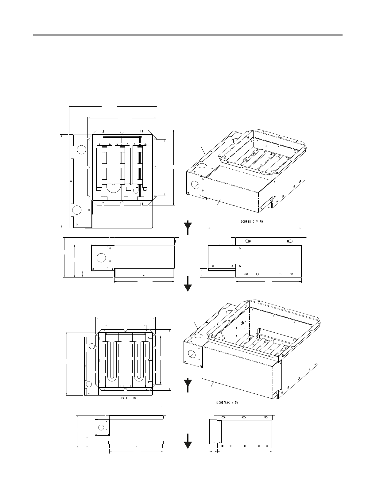
Accessory Heater Dimensions
The maximum recommended air velocity for a supply plenum is 900 fpm. When connecting a plenum to an external
supplemental heater, ensure that the air velocity in the plenum does not exceed 900 fpm. Noise and air distribution issues
may occur if supply plenum velocities exceed 900 fpm.
AGM4A - 12A
AGL10A - 20A
14.7 Control
box
Element
cover
10.3
15.5
16.1
8.1
3
13.3 13.5
2
15.1
12
Discharge Air Opening Discharge Air Opening
14.7 Control
box
Element
cover
10.3
15.5
16.1
8.1
3
13.3 13.5
2
15.1
12
A
I
R
F
L
O
W
Discharge Air Opening
Discharge Air Opening
A
I
R
F
L
O
W
Rev. A 13.6
Rev. B 14.9
Rev. A 10.7
Rev. B 12.0
14.6
8.8
11.7
Control box
Element
cover
6.2
5.1
Rev. A 9.4
Rev. B 10.6
10.2
1
14.6
1.4
13.6
10.7
Rev. A 13.6
Rev. B 14.9
Rev. A 10.7
Rev. B 12.0
14.6
8.8
11.7
Control box
Element
cover
6.2
5.1
Rev. A 9.4
Rev. B 10.6
10.2
1
14.6
1.4
9.4

Electric Heat - Installation, Operation, and Maintenance
Revised: 04 August, 2015
10 ClimateMaster Geothermal Heating and Cooling
CLIMATE MASTER, INC.
LIMITED EXPRESS WARRANTY/LIMITATION OF REMEDIES AND LIABILITY FOR
RESIDENTIAL CLASS PRODUCTS WITH LABOR ALLOWANCE
It is expressly understood that unless a statement is specically identied as a warranty, statements made by Climate Master, Inc. a Delaware corporation, (“CM”) or its representatives, relating to CM’s products, whether oral, written or contained
in any sales literature, catalog or agreement, are not express warranties and do not form a part of the basis of the bargain, but are merely CM’s opinion or commendation of CM’s products. EXCEPT AS SPECIFICALLY SET FORTH
HEREIN, THERE IS NO EXPRESS WARRANTY AS TO ANY OF CM’S PRODUCTS. CM MAKES NO WARRANTY AGAINST LATENT DEFECTS. CM MAKES NO WARRANTY OF MERCHANTABILITY OF THE
GOODS OR OF THE FITNESS OF THE GOODS FOR ANY PARTICULAR PURPOSE.
GRANT OF LIMITED EXPRESS WARRANTY
CM warrants its Residential Class products, purchased and retained in the United States of America and Canada, to be free from defects in material and workmanship under normal use and maintenance as follows: (1) Air conditioning, heating
and/or heat pump units built or sold by CM (“CM Units”) for ten (10) years from the Warranty Inception Date (as dened below); (2) Thermostats, auxiliary electric heaters and geothermal pumping modules built or sold by CM, when installed
with CM Units, for ten (10) years from the Warranty Inception Date (as dened below); and (3) Other accessories and parts built or sold by CM, when installed with CM Units, for one (1) year from the date of shipment from CM. The “Warranty
Inception Date” shall be the date of original unit installation, or six (6) months from date of unit shipment from CM, whichever comes rst.
To make a claim under this warranty, parts must be returned to CM in Oklahoma City, Oklahoma, freight prepaid, no later than ninety (90) days after the date of the failure of the part; if CM determines the part to be defective and within CM’s
Limited Express Warranty, CM shall, when such part has been either replaced or repaired, return such to a factory recognized distributor, dealer or service organization, F.O.B. CM, Oklahoma City, Oklahoma, freight prepaid. The warranty on
any part repaired or replaced under warranty expires at the end of the original warranty period.
This Limited Express Warranty shall cover the labor incurred by CM authorized service personnel in connection with the installation of a new or repaired warranty part that is covered by this Limited Express Warranty only to the extent
specically set forth in the then existing labor allowance schedule provided by CM’s Warranty Department and only as follows: (1) CM Units for ve (5) years from the Warranty Inception Date; (2) Thermostats, auxiliary electric heaters and
geothermal pumping modules built or sold by CM, when installed with CM Units, for ve (5) years from the Warranty Inception Date. Actual Labor costs are not covered by this Limited Express Warranty to the extent they exceed the amount
allowed under said allowance schedule, they are not specically provided for in said allowance schedule, they are not the result of work performed by CM authorized service personnel, they are incurred in connection with a part not covered by
this Limited Express Warranty, or they are incurred more than the time periods set forth in this paragraph after the Warranty Inception Date.
This warranty does not cover and does not apply to: (1) Air lters, fuses, refrigerant, uids, oil; (2) Products relocated after initial installation; (3) Any portion or component of any system that is not supplied by CM, regardless of the cause of the
failure of such portion or component; (4) Products on which the unit identication tags or labels have been removed or defaced; (5) Products on which payment to CM, or to the owner’s seller or installing contractor, is in default; (6) Products
subjected to improper or inadequate installation, maintenance, repair, wiring or voltage conditions; (7) Products subjected to accident, misuse, negligence, abuse, re, ood, lightning, unauthorized alteration, misapplication, contaminated
or corrosive air or liquid supply, operation at abnormal air or liquid temperatures or ow rates, or opening of the refrigerant circuit by unqualied personnel; (8) Mold, fungus or bacteria damages; (9) Corrosion or abrasion of the product;
(10) Products supplied by others; (11) Products which have been operated in a manner contrary to CM’s printed instructions; (12) Products which have insufcient performance as a result of improper system design or improper application,
installation, or use of CM’s products; or (13) Electricity or fuel costs, or any increases or unrealized savings in same, for any reason whatsoever.
This Limited Express Warranty provides the limited labor allowance coverage as set forth above. Otherwise, CM is not responsible for: (1) The costs of any uids, refrigerant or system components supplied by others, or associated labor to repair
or replace the same, which is incurred as a result of a defective part covered by CM’s Limited Express Warranty; (2) The costs of labor, refrigerant, materials or service incurred in diagnosis and removal of the defective part, or in obtaining and
replacing the new or repaired part; (3) Transportation costs of the defective part from the installation site to CM, or of the return of that part if not covered by CM’s Limited Express Warranty; or (4) The costs of normal maintenance.
This Limited Express Warranty applies to CM Residential Class products ordered from CM on or after May 1, 2010 (this would generally include CM Units with serial numbers beginning with “N118” and higher), and is not retroactive to any
products ordered from CM prior to May 1, 2010 (this would generally include CM Units with serial numbers beginning with “N117” and lower). If you are unsure if this Limited Express Warranty applies to the product you have purchased,
contact CM at the phone number or address reected below.
Limitation: This Limited Express Warranty is given in lieu of all other warranties. If, notwithstanding the disclaimers contained herein, it is determined that other warranties exist, any such express warranty, including without limitation any
express warranties or any implied warranties of tness for particular purpose and merchantability, shall be limited to the duration of the Limited Express Warranty.
LIMITATION OF REMEDIES
In the event of a breach of the Limited Express Warranty, CM will only be obligated at CM’s option to repair the failed part or unit, or to furnish a new or rebuilt part or unit in exchange for the part or unit which has failed. If after written notice
to CM’s factory in Oklahoma City, Oklahoma of each defect, malfunction or other failure, and a reasonable number of attempts by CM to correct the defect, malfunction or other failure, and the remedy fails of its essential purpose, CM shall
refund the purchase price paid to CM in exchange for the return of the sold good(s). Said refund shall be the maximum liability of CM. THIS REMEDY IS THE SOLE AND EXCLUSIVE REMEDY OF THE BUYER OR PURCHASER
AGAINST CM FOR BREACH OF CONTRACT, FOR THE BREACH OF ANY WARRANTY OR FOR CM’S NEGLIGENCE OR IN STRICT LIABILITY.
LIMITATION OF LIABILITY
CM shall have no liability for any damages if CM’s performance is delayed for any reason or is prevented to any extent by any event such as, but not limited to: any war, civil unrest, government restrictions or restraints, strikes, or
work stoppages, re, ood, accident, shortages of transportation, fuel, material, or labor, acts of God or any other reason beyond the sole control of CM. CM EXPRESSLY DISCLAIMS AND EXCLUDES ANY LIABILITY FOR
CONSEQUENTIAL OR INCIDENTAL DAMAGE IN CONTRACT, FOR BREACH OF ANY EXPRESS OR IMPLIED WARRANTY, OR IN TORT, WHETHER FOR CM’s NEGLIGENCE OR AS STRICT LIABILITY.
OBTAINING WARRANTY PERFORMANCE
Normally, the dealer or service organization who installed the products will provide warranty performance for the owner. Should the installer be unavailable, contact any CM recognized distributor, dealer or service organization. If assistance is
required in obtaining warranty performance, write or call:
Climate Master, Inc. • Customer Service • 7300 SW 44th Street • Oklahoma City, Oklahoma 73179 • (405) 745-6000 • e-service@climatemaster.com
NOTE: Some states or Canadian provinces do not allow limitations on how long an implied warranty lasts, or the limitation or exclusions of consequential or incidental damages, so the foregoing exclusions and limitations may not apply to you.
This warranty gives you specic legal rights, and you may also have other rights which vary from state to state and from Canadian province to Canadian province.
Please refer to the CM Installation, Operation and Maintenance Manual for operating and maintenance instructions. Rev.: 4/10
Part No.: RP851
Warranty

11
Electric Heat - Installation, Operation, and Maintenance
Revised: 04 August, 2015
climatemaster.com
Revision History
R
M
A
N
U
F
A
C
T
U
R
E
R
C
E
R
T
I
F
I
E
D
T
O
A
R
I
A
S
C
O
M
P
L
Y
I
N
G
W
I
T
H
I
S
O
S
T
A
N
D
A
R
D
1
3
2
5
6
-
1
H
E
A
T
P
U
M
P
S
W
A
T
E
R
T
O
A
I
R
B
R
I
N
E
T
O
A
I
R
97B0005N04
ClimateMaster works continually to improve its products. As a result, the design and specications of each product at the time for order may be
changed without notice and may not be as described herein. Please contact ClimateMaster’s Customer Service Department at 1-405-745-6000
for specic information on the current design and specications. Statements and other information contained herein are not express warran-
ties and do not form the basis of any bargain between the parties, but are merely ClimateMaster’s opinion or commendation of its products.
The management system governing the manufacture of ClimateMaster’s products is ISO 9001:2008 certied.
© ClimateMaster, Inc. 2014
*97B0005N04*
7300 S.W. 44th Street
Oklahoma City, OK 73179
Phone: 405-745-6000
Fax: 405-745-6058
climatemaster.com
ISO 9001:2008
Certified
Quality: First & Always
Date Page # Description
04 Aug., 2015 9 Updated Illustration Title AGL10A - 20A
09 Feb., 2015 All Misc Edits
22 Dec., 2014 5 External Installation Instructions Updated
29 Oct., 2014 All First Published
Other manuals for AG Series
2
Table of contents
Other ClimateMaster Electric Heater manuals


