ClimateMaster Tranquility Low-Profile Series Owner's manual
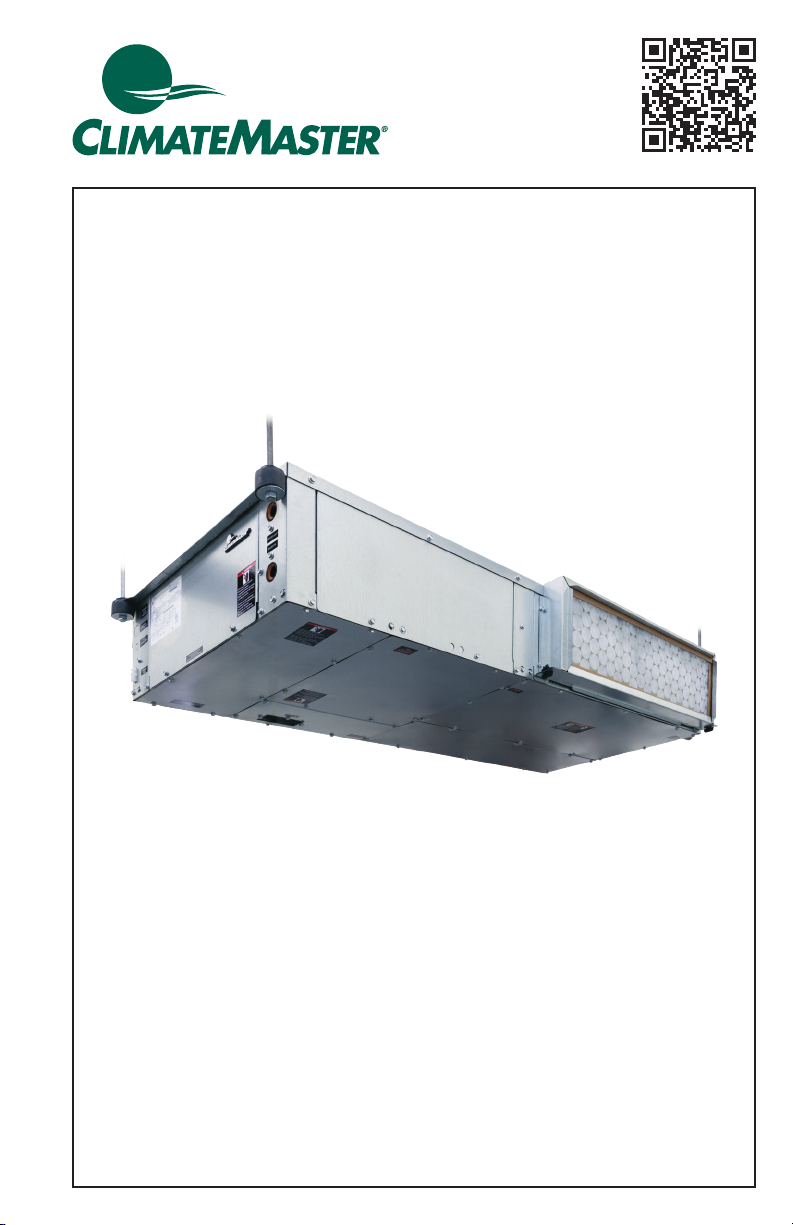
Tranquility®
Low-Profile
(TRL) Series
Models TRL 006 - 015
60Hz - HFC-410A
INSTALLATION, OPERATION
& MAINTENANCE
97B0001N15
Created: November 11, 2021

CLIMATEMASTER WATER-SOURCE HEAT PUMPS
Tranquility®(TRL)Series
Rev.: November 11, 2021
ClimateMaster Water-Source Heat Pumps
2
This page intentionally left blank.

climatemaster.com 3
Tranquility®(TRL)Series
Rev.: November 11, 2021
CLIMATEMASTER WATER-SOURCE HEAT PUMPS
Table of Contents
Model Nomenclature - General Overview.......................................................................................4
General Information............................................................................................................................ 5-7
Unit Physical Data....................................................................................................................................8
TRL – Horizontal Dimensional Drawing...........................................................................................9
TRL – Horizontal Service Access..................................................................................................... 10
Horizontal Installation ...................................................................................................................11-13
Condensate Installation....................................................................................................................... 14
Ductwork Installation ....................................................................................................................15-17
Unit Access.......................................................................................................................................18-20
Piping Installation ...........................................................................................................................21-22
Internal Water Pump Performance ................................................................................................. 23
Water-Loop Heat Pump Applications.....................................................................................24-25
Ground-Loop Heat Pump Applications..................................................................................26-27
Electrical - Line Voltage....................................................................................................................... 28
Electrical Data ........................................................................................................................................ 29
Electrical - Power Wiring.............................................................................................................30-31
Electrical - Power & Low Voltage Wiring ..............................................................................32-33
Electrical - Low Voltage Wiring........................................................................................................ 34
Electrical - Thermostat Wiring.......................................................................................................... 35
Blower Performance Data ................................................................................................................. 36
TRL Series Wiring Diagram Matrix ................................................................................................. 37
CXM2 Controls ................................................................................................................................38-42
Safety Features - CXM2 Controls.............................................................................................43-45
Unit Starting and Operating Conditions.................................................................................46-47
Water Quality Standards.............................................................................................................48-51
Piping System Cleaning and Flushing ....................................................................................52-53
Unit and System Checkout..........................................................................................................54-55
Unit Start-Up Procedure ..............................................................................................................56-58
Unit Operating Conditions...........................................................................................................59-61
Preventive Maintenance...............................................................................................................62-63
Functional Troubleshooting.........................................................................................................64-67
Performance Troubleshooting....................................................................................................68-70
Start-Up Log Sheet............................................................................................................................... 71
Functional Troubleshooting Form .............................................................................................72-73
Warranty (U.S. & Canada) .................................................................................................................. 74
Revision History..................................................................................................................................... 76

CLIMATEMASTER WATER-SOURCE HEAT PUMPS
Tranquility®(TRL)Series
Rev.: November 11, 2021
ClimateMaster Water-Source Heat Pumps
4
Model Nomenclature – General Overview
NOTES:
1. All products come standard with Braze Plate Heat Exchangers (BPHE).
2. Products with the Extended Range option come with the BPHE and all copper tubing insulated.
The units are equipped with low temperature discharge line/low pressure sensors for extended
operating range conditions.
T R
1 2
L
3
0 1 2
4 5 6
A
7
G
8
C
9
3
10
0
11
C
12
S
15
S
13
2
14
TR = TRANQUILITY
HIGH
EFFICIENCY 410A
MODELTYPE
L - HORIZONTAL LOW PROFILE
CONFIGURATION
006 - G
009 - G
012 - G
015 - G
UNIT SIZE
A = CURRENT REVISION
REVISION LEVEL
G = 208-230/60/1
VOLTAGE
S = LEFT RETURN, STAINLESS STEEL DRAIN PAN
T = RIGHT RETURN, STAINLESS STEEL DRAIN PAN
RETURN AIR OPTIONS
0 = None
7 = Internal Circulating Pump
M = Motorized Water Valve
F = 2.5 GPM/Ton Auto Flow Regulator
L = 3.0 GPM/Ton Auto Flow Regulator
W = 2.5 GPM/Ton Auto Flow Regulator & Motorized Water Valve
V = 3.0 GPM/Ton Auto Flow Regulator & Motorized Water Valve
WATER CIRCUIT OPTIONS
CONTROLS
CABINET INSULATION
WATER FLOW SWITCH & AIR COIL OPTIONS
SUPPLY AIR OPTIONS
S = STANDARD
STANDARD DISCONNECT
CXM2
CXM2 w/MPC
C
N
A
R
K
A
STANDARD
M
C
ULTRA QUIET
P
E
STANDARD
S
G
ULTRA QUIET
EXTENDED RANGE STANDARD RANGE
1” FILTER FRAME
2” FILTER FRAME
Option Supply
A
Straight
C
NON
COATED
AIR COIL
Standard A
TIN
COATED
AIR COIL
E
E-COATED
AIR COIL
High Pressure
WATER FLOW
SWITCH TYPE
5 6 7
B
C
D
Straight + Back
E
F
G Back
0 Field Configured
Opening
Area (in)
006 or
009
012 or
015
8x6
16x6
24x6
8x6 + 7x6
16x6 + 7x6
24x6 + 7x6
7x6
-
X
X
N/A
X
N/A
N/A
X
X
N/A
X*
X
X*
X
X
N/A
X
* For sizes 012-015 this configuration will have internal static pressure
losses up to 0.2.
Note: Above model nomenclature is a general reference. Not all congurations are available on all models.
Consult selection software for detailed information.
climatemaster.com 5
Tranquility®(TRL)Series
Rev.: November 11, 2021
CLIMATEMASTER WATER-SOURCE HEAT PUMPS
General Information
Safety
Warnings, cautions, and notices appear
throughout this manual. Read these
items carefully before attempting any
installation, service, or troubleshooting of
the equipment.
DANGER: Indicates an immediate
hazardous situation, which if not avoided
will result in death or serious injury.
DANGER labels on unit access panels
must be observed.
WARNING: Indicates a potentially
hazardous situation, which if not avoided
could result in death or serious injury.
CAUTION: Indicates a potentially
hazardous situation or an unsafe
practice, which if not avoided could
result in minor or moderate injury or
product or property damage.
NOTICE: Notication of installation,
operation, or maintenance information,
which is important, but which is not
hazard-related.
WARNING! The EarthPure®
Application and Service Manual
should be read and understood
before attempting to service
refrigerant circuits with HFC-410A.
⚠
WARNING!
⚠
⚠
WARNING!
⚠
WARNING! To avoid the release of
refrigerant into the atmosphere, the
refrigerant circuit of this unit must
be serviced only by technicians
who meet local, state, and federal
prociency requirements.
⚠
CAUTION!
⚠
CAUTION! To avoid equipment
damage, DO NOT use these units
as a source of heating or cooling
during the construction process. The
mechanical components and lters
can quickly become clogged with
construction dirt and debris, which
may cause system damage and void
product warranty.
⚠
WARNING!
⚠
WARNING! The installation of water-
source heat pumps and all associated
components, parts, and accessories
which make up the installation shall
be in accordance with the regulations
of ALL authorities having jurisdiction
and MUST conform to all applicable
codes. It is the responsibility of the
installing contractor to determine and
comply with ALL applicable codes
and regulations.
⚠
WARNING!
⚠
WARNING! All refrigerant discharged
from this unit must be recovered
WITHOUT EXCEPTION. Technicians
must follow industry accepted
guidelines and all local, state, and
federal statutes for the recovery
and disposal of refrigerants. If a
compressor is removed from this unit,
refrigerant circuit oil will remain in
the compressor. To avoid leakage of
compressor oil, refrigerant lines of the
compressor must be sealed after it is
removed.

CLIMATEMASTER WATER-SOURCE HEAT PUMPS
Tranquility®(TRL)Series
Rev.: November 11, 2021
ClimateMaster Water-Source Heat Pumps
6
General Information, Cont’d.
Inspection - Upon receipt of the
equipment, carefully check the shipment
against the bill of lading. Make sure all
units have been received. Inspect the
packaging of each unit, and inspect each
unit for damage. Ensure that the carrier
makes proper notation of any shortages
or damage on all copies of the freight
bill and completes a common carrier
inspection report. Concealed damage
not discovered during unloading must be
reported to the carrier within 15 days of
receipt of shipment. If not led within 15
days, the freight company can deny the
claim without recourse.
Note: It is the responsibility of the
purchaser to le all necessary claims
with the carrier. Notify your equipment
supplier of all damage within fteen (15)
days of shipment.
Storage - Equipment should be stored in
its original packaging in a clean, dry area.
Store units in an upright position at all
times. Stack units a maximum of 3 units
high.
Unit Protection - Cover units on the job
site with either the original packaging or
an equivalent protective covering. Cap
the open ends of pipes stored on the job
site. In areas where painting, plastering,
and/or spraying has not been completed,
all due precautions must be taken to
avoid physical damage to the units
and contamination by foreign material.
Physical damage and contamination may
prevent proper start-up and may result in
costly equipment clean-up.
Examine all pipes, ttings, and valves
before installing any of the system
components. Remove any dirt or debris
found in or on these components.
Pre-Installation - Installation, Operation,
and Maintenance instructions are
provided with each unit. Horizontal
equipment is designed for installation
above false ceiling or in a ceiling plenum.
Other unit congurations are typically
installed in a mechanical room. The
installation site chosen should include
adequate service clearance around the
unit. Before unit start-up, read all manuals
and become familiar with the unit and its
operation. Thoroughly check the system
before operation.
Prepare units for installation as follows:
1. Compare the electrical data on the
unit nameplate with ordering and
shipping information to verify that
the correct unit has been shipped.
2. Keep the cabinet covered with the
original packaging until installation is
complete and all plastering, painting,
etc. is nished.
3. Verify refrigerant tubing is free of
kinks or dents and that it does not
touch other unit components.
4. Inspect all electrical connections.
Connections must be clean and tight
at the terminals.
5. Remove any blower support
packaging (water-to-air units only).
6. Conrm supply air conguration
matches duct design plans.
7. Locate and verify the hanger kit
and other provided eld installed
parts have been removed from the
compressor and blower sections of
the unit.
8. The unit is shipped with plastic plugs
(hand-tightened) to protect the water
lines from debris or contaminant
agents that might affect the BPHE,
remove before connecting the unit to
the main water loop.
climatemaster.com 7
Tranquility®(TRL)Series
Rev.: November 11, 2021
CLIMATEMASTER WATER-SOURCE HEAT PUMPS
General Information, Cont’d.
⚠
CAUTION!
⚠
CAUTION! DO NOT store or install
units in corrosive environments or
in locations subject to temperature
or humidity extremes (e.g., attics,
garages, rooftops, etc.). Corrosive
conditions and high temperature or
humidity can signicantly reduce
performance, reliability, and service
life. Always move and store units in an
upright position. Tilting units on their
sides will cause equipment damage.
⚠
CAUTION!
⚠
CAUTION! CUT HAZARD - Failure
to follow this caution may result in
personal injury. Sheet metal parts
may have sharp edges or burrs. Use
care and wear appropriate protective
clothing, safety glasses and gloves
when handling parts and servicing
heat pumps.
⚠
WARNING!
⚠
WARNING! This product can
expose you to chemicals including
formaldehyde, which is known to the
state of California to cause cancer. For
more information, go to
www.P65Warnings.ca.gov.

CLIMATEMASTER WATER-SOURCE HEAT PUMPS
Tranquility®(TRL)Series
Rev.: November 11, 2021
ClimateMaster Water-Source Heat Pumps
8
Unit Physical Data
Tranquility®(TRL)Series (60 Hz)
Model TRL006 TRL009 TRL012 TRL015
Factory Charge R410A - (oz.) 19 19 26 28
Motor & Blower
ECM Constant Torque (HP) [W] 0.25 [186]
Blower Wheel Size (Dia x W) 5.7 x 7.98 (1pc) 5.7 x 7.98 (2pc)
Water Connection Size
Water volume (gal)* 0.037 0.042 0.049
FPT - All Other 1/2” FPT
Horizontal
Filter Standard - 1” Throwaway 8.5 x 28 x 1
Filter Standard - 2” Throwaway 8.5 x 28 x 2
Weight - Operating (lbs.) 145 146 152 159
Weight - Packaged (lbs.) 185 186 192 199
*Volume for BPHE only
Unit Maximum Water Working Pressure Max Pressure PSIG
[kPa]
Base Unit 500 [3447]
Internal Secondary Pump (ISP) 200 [1379]
Internal Motorized Water Valve (MWV) 300 [2068]
Internal Auto Flow Valve 300 [2068]
20 Mesh Y Strainer Valve 600 [4137]
Flow switch - Low Pressure System 160 [1103]
Flow switch - High Pressure System 360 [2482]

climatemaster.com 9
Tranquility®(TRL)Series
Rev.: November 11, 2021
CLIMATEMASTER WATER-SOURCE HEAT PUMPS
TRL – Horizontal Dimensional Drawing
A
22.500
FRONT
WATER OUT
1/2"fpt
WATER IN
1/2"fpt
CEP
HIGH VOLTAGE
WIRING K.O.
LOW VOLTAGE
WIRING K.O.
J4.532
K
3.157
H
.975
E
1.781
D
6.408
2.377
F
REAR
BACK FIELD CONFIGURED
SUPPLY AIR KNOCK OUT
CONDENSATE
DRAIN
RETURN
AIR
ASP
AA
2.540
BB
.471
V
21.155
U
54.718
TOP
HANGER POINTS 4X
RETURN
AIR
BOTTOM
BAP
WRP
CEP
C
9.000
B
53.006
RIGHT AIR DISCHARGE 3X
FIELD CONFIGURABLE
KNOCKOUTS
ASP
N
24.000
O
2.978
.906
M
6.000
1.578 P
Q
26.378
ASP
LEFT
S
1.742
R
7.052
T
.811
RIGHT RETURN
BOTTOM ISO VIEW
ASP
WRP
BAP
SUPPLY AIR
KNOCKOUTS
LEFT RETURN
BOTTOM ISO VIEW
CEP
ASP
BAP
SUPPLY AIR
KNOCKOUTS
CEP
WRP
CEP
SERVICE TOOL
CONNECTION
CEP
SERVICE TOOL
CONNECTION
Notes:
1. While clear access to all removable panels is not required, installer should take care to comply with all
building codes and allow adequate clearance for future eld service.
2. Units shipped with lter frames with duct mounting collar for connection to return air duct connection.
3. Hanger brackets are designed into the top panel of the unit.
4. Units are provided with a 1/2” MPT condensate connection. There is also a condensate connection kit
provided in the unit which contains a exible coupling that can be used to connect to 3/4” PVC or 1” Copper.
5. Blower service access can be from the bottom, side, or top.
6. Bottom blower access allows blower assembly to be dropped, disconnected, and removed for servicing.
7. An installation kit that includes the hanger hardware and condensate coupling is attached the unit side
access panel. Remove before installing.
Legend:
CEP = Controls & Electrical Service Panel
BAP = Blower, Air Coil & Drain Pan Service Panel
WRP = Water & Refrigerant Service Panel
*ASP = Additional Service Panel (not required)
Note:
*ASP are removable panels that provide additional
access to the units interior. Clear access to ASP panels
is not required and they are not to be used in place of
the mandatory CEP, WRP, or BAP panels.

CLIMATEMASTER WATER-SOURCE HEAT PUMPS
Tranquility®(TRL)Series
Rev.: November 11, 2021
ClimateMaster Water-Source Heat Pumps
10
TRL – Horizontal Service Access
Air Coil
Front
ASP ASP
CEP
ASP
Return
Air Flow
Supply
Air Flow
Top View - Left Return Straight Discharge Top View - Right Return Straight Discharge
Ceiling Hung - Left Return Straight Discharge
ASPRETURN AIR
BAP CEP
Front Access Panel
Ceiling Hung - Right Return Straight Discharge
ASP RETURN AIR
BAP
CEP
Front Access Panel
ASP ASP
CEP
ASP
Return
Air Flow
Supply
Air Flow
Air Coil
Front
= Mandatory 3′Service Access = Optional 2′Service Access= Mandatory 1′Service Access
(front access service should be
increased if external pumps,
valves, etc. are applied)
Notes:
1. While clear access to all removable panels is not required, installer should take care to comply with all
building codes and allow adequate clearance for future eld service.
2. CEP and BAP requires 2’ bottom service access. CEP requires 2’ front service access as well. Ceiling
mounted service access doors are acceptable. BAP side service access is optional.
3. ASP are removable panels that provide additional access to the units interior. Clear access to ASP panels
is not required and they are not to be used in place of the mandatory CEP and BSP panels.
4. For back discharge congurations, supply air is delivered to the back of the unit (side opposite of the
controls) and all blower service access is from the bottom. Not all sizes available in back discharge only.
Please see the Ductwork Installation section for details.
5. For back and straight combined discharge congurations, all blower service access is from the bottom.
Legend:
CEP = Controls & Electrical Service Panel
BAP = Blower, Air Coil, & Drain Pan Service Panel
WRP = Water & Refrigerant Service Panel
ASP = Additional Service Panel (not required)

climatemaster.com 11
Tranquility®(TRL)Series
Rev.: November 11, 2021
CLIMATEMASTER WATER-SOURCE HEAT PUMPS
Horizontal Installation
Horizontal Unit Location
Units are not designed for outdoor
installation. Locate the unit in an INDOOR
area that allows enough space for service
personnel to perform typical maintenance
or repairs without removing unit from
the ceiling. Horizontal units are typically
installed above a false ceiling or in a
ceiling plenum. Never install units in areas
subject to freezing or where humidity
levels could cause cabinet condensation
(such as unconditioned spaces subject to
100% outside air). Consideration should
be given to access for easy removal of the
lter and access panels. Provide sufcient
room to make water, electrical, and duct
connection(s).
TRL units are designed to be accessed
from the bottom for servicing. Sufcient
clearance should be given underneath the
unit for access to bottom service panels.
If the unit is located in a conned space,
such as a closet, provisions must be made
for return air to freely enter the space by
means of a louvered door, etc. Any access
panel screws that would be difcult to
remove after the unit is installed should
be removed prior to setting the unit. Refer
to Figure 3 for an illustration of a typical
installation. Refer to unit submittal data for
dimensional data.
Conform to the following guidelines
when selecting unit location:
1. Provide a hinged access door in
concealed-spline or plaster ceilings.
Provide removable ceiling tiles in T-bar
or lay-in ceilings. Refer to horizontal
unit dimensions for specic series and
model in unit submittal data. Size the
access opening to accommodate the
service technician during the removal
or replacement of the compressor,
control, or blower assembly.
2. Provide access to hanger brackets,
water valves and ttings. Provide
screwdriver clearance to access
panels, discharge collars and all
electrical connections.
3. DO NOT obstruct the space beneath
the unit with piping, electrical cables
and other items that prohibit future
removal of components or the unit
itself.
4. Use a manual portable jack/lift to lift
and support the weight of the unit
during installation and servicing.
The installation of water source heat pump
units and all associated components,
parts and accessories which make up the
installation shall be in accordance with
the regulations of ALL authorities having
jurisdiction and MUST conform to all
applicable codes. It is the responsibility of
the installing contractor to determine and
comply with ALL applicable codes and
regulations.

CLIMATEMASTER WATER-SOURCE HEAT PUMPS
Tranquility®(TRL)Series
Rev.: November 11, 2021
ClimateMaster Water-Source Heat Pumps
12
Horizontal Installation Cont’d.
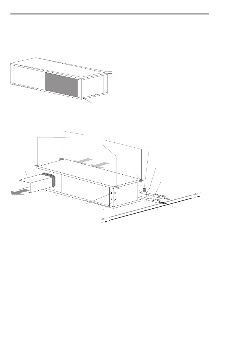
Mounting Horizontal Units
Horizontal units have 4 hanger brackets
designed into the top panel of the unit,
one at each corner. Enclosed within the
unit there is a hanger kit hardware bag
containing vibration isolation grommets,
washers and a hanger installation
instruction page. See Figure 1. Refer to
the hanger installation instruction page
contained in the hardware bag for details
of nal hanger bracket attachment and
unit suspension. See Figure 1a.
Use four (4) eld supplied 3/8” diameter
threaded rods and factory provided
vibration isolators to suspend the unit.
Safely lift the unit into position supporting
the bottom of the unit. Ensure the top of
the unit is not in contact with any external
objects. Connect the top end of the 4
all-thread rods, slide rods through the
brackets and grommet then assemble
washers and double nuts at each rod.
Ensure that the unit is approximately level
and that the threaded rod extends past
the nuts.
Pitch the unit toward the drain as shown
in Figure 2 to improve the condensate
drainage. Ensure that unit pitch does
not cause condensate leaks inside the
cabinet. Cut any remaining all thread
below the lower nut so that it does not
interfere with any electrical or water
connections on the front of the unit.
Figure 1: Hanger Bracket
Figure 1a:
climatemaster.com 13
Tranquility®(TRL)Series
Rev.: November 11, 2021
CLIMATEMASTER WATER-SOURCE HEAT PUMPS
Horizontal Installation, Cont’d.
Figure 2: Horizontal Unit Pitch
(by others)
Water In
Water Out
Optional Balancing Valve
Ball Valve with optional
integral P/T plug and strainer
Stainless steel braid hose
with integral "J" swivel
Building
Loop
Return Air
Supply Air
3/8" [10mm] threaded rods
Unit Power
Flexible Duct
Connector
Optional Low Pressure Drop Water
Control Valve
(can be internally mounted
on some models)
Insulated
Supply Duct
Thermostat
Wiring
Unit Hanger
Figure 3: Typical Horizontal Unit Installation
Air Coil - To obtain maximum
performance, the air coil should be
cleaned before start-up. A 10% solution
of dishwasher detergent and water is
recommended for both sides of the coil.
A thorough water rinse should follow.
UV based anti-bacterial systems may
damage e-coated air coils.
Notice! Installation Note - Ducted Return:
Many horizontal WSHPs are installed in a
return air ceiling plenum application (above
ceiling). All TRL products are equipped
with lter frames for ducted or non-ducted
returns. Canvas or exible connectors
should also be used to minimize vibration
between the unit and ductwork.
1/4” (6.4mm) pitch
toward drain for drainage
Drain Connection
CLIMATEMASTER WATER-SOURCE HEAT PUMPS
Tranquility®(TRL)Series
Rev.: November 11, 2021
ClimateMaster Water-Source Heat Pumps
14
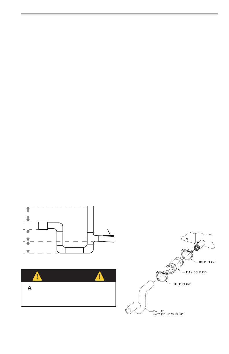
Condensate Installation
Condensate Piping - Horizontal Units -
A condensate drain line must be installed
and pitched away for the unit to allow for
proper drainage. This connection must
meet all local plumbing/building codes.
Pitch the unit toward the drain as shown
in Figure 2 to improve the condensate
drainage. Ensure that unit pitch does not
cause condensate leaks inside the cabinet.
Install condensate trap at each unit with
the top of the trap positioned below
the unit condensate drain connection
as shown in Figure 4. As a general rule,
the minimum depth for traps is 1-1/2
inches. Each unit must be installed with
its own individual trap and connection
to the condensate line (main) or riser.
Provide a means to ush or blow out the
condensate line. DO NOT install units
with a common trap and/or vent.
Figure 4: Horizontal Condensate
Connection
2”
1.5”
1.5”
1/8” Per
Foot
Always vent the condensate line when
dirt or air can collect in the line or a long
horizontal drain line is required. Also vent
when large units are working against
higher external static pressure than other
units connected to the same condensate
main since this may cause poor drainage
for all units on the line.
WHEN A VENT
IS INSTALLED IN THE DRAIN LINE,
IT MUST BE LOCATED AFTER THE
TRAP IN THE DIRECTION OF THE
CONDENSATE FLOW.
Some applications will require condensate
pumping due to limited ceiling space or
the need to connect to a main drain line
higher in elevation. Condensate pumps
are to be eld provided and are mounted
externally to the unit.
Units are provided with a 1/2" MPT
condensate connection. There is also a
condensate connection kit provided in
the unit which contains a exible coupling
that can be used to connect to 3/4" PVC
or 1" Copper. Dispose of kit if not used.
See gure 5.
Figure 5: Condensate Kit
⚠
CAUTION!
⚠
CAUTION! Ensure condensate line
is pitched toward drain 1/8 inch per ft
[11mm per m] of run.

climatemaster.com 15
Tranquility®(TRL)Series
Rev.: November 11, 2021
CLIMATEMASTER WATER-SOURCE HEAT PUMPS
Duct Work Installation
Proper duct sizing and design is critical
to the performance of the unit. The duct
system should be designed to allow
adequate and even airow through the
unit during operation. Air ow through the
unit MUST be at or above the minimum
stated airow for the unit to avoid
equipment damage. Duct systems should
be designed for quiet operation. Refer to
Figure 6 for horizontal duct system details.
A exible connector is recommended
for both discharge and return air duct
connections on metal duct systems to
eliminate the transfer of vibration to
the duct system. To maximize sound
attenuation of the unit blower, the supply
and return plenums should include internal
berglass duct liner or be constructed
from duct board for the rst few feet.
Application of the unit to uninsulated
ductwork in an unconditioned space is not
recommended, as the unit’s performance
may be adversely affected.
If air noise or excessive air ow is a
problem, the blower speed can be
changed. For airow charts, consult
submittal data for the series and model of
the specic unit.
If the unit is connected to existing
ductwork, a previous check should have
been made to ensure that the ductwork has
the capacity to handle the airow required
for the unit. If ducting is too small, as in
the replacement of a heating only system,
larger ductwork should be installed. All
existing ductwork should be checked for
leaks and repaired as necessary.
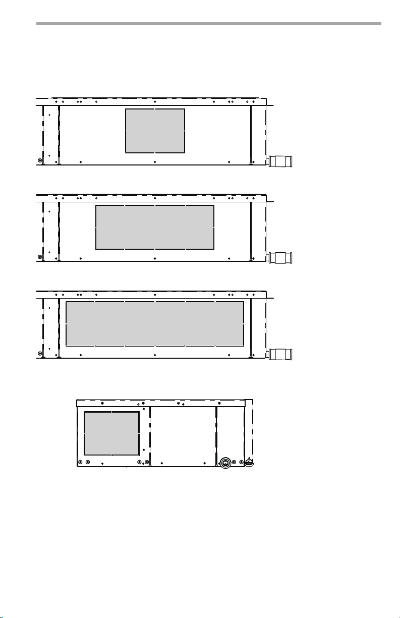
TRL products can be supplied with factory
or eld congured supply air openings. If
factory congured supply air openings are
desired, the congurations can be either left
or right return air with right or left supply
air. Back supply air can also be selected
as eld or factory congured but must be
paired with left or right supply air openings
on sizes 12 and 15. Please refer to Tables 1,
2, and 3 for minimum and maximum supply
air openings by size.
Flanges for connection to the supply air
are provided when factory congured
supply air openings are ordered. When
eld congured supply air openings
are selected, supply air anges are
integrated into the cabinet design.
Perforated supply air openings are
knocked out and then the supply air
anges are bent back for connection to
supply air plenum or duct work.
NOTES: Only TRL sizes 006-009 can
be applied as back discharge supply
air only. Sizes 012-015 must be
applied as side discharge supply air
with the option to be combined with
back discharge supply air. Return air
congurations can not be converted in
the eld.
CLIMATEMASTER WATER-SOURCE HEAT PUMPS
Tranquility®(TRL)Series
Rev.: November 11, 2021
ClimateMaster Water-Source Heat Pumps
16
Duct Work Installation, Cont’d.
8 x 6
24 x 6
Figure 6: Side Discharge Supply Air Openings
16 x 6
7 x 6
Figure 6a: Back Discharge Supply Air Opening

climatemaster.com 17
Tranquility®(TRL)Series
Rev.: November 11, 2021
CLIMATEMASTER WATER-SOURCE HEAT PUMPS
Duct Work Installation, Cont’d.
Size Right/Left SA Opening Sizes Back SA Opening
006-009 8 x 6 or 16 x 6 7 x 6
012-015 16 x 6 or 24 x 6 7 x 6
All dimensions shown in inches.
Table 1: Supply Air (SA) Opening Dimensional Data
Size Number of
Openings
Minimum Sq. in.
Opening*
Maximum Sq. in.
Opening
Recommended Sq. in.
Opening
006-009 1 or 2 42 96 48
012-015 1 or 2 90 186 144
All dimensions shown in inches.
* Less than minimum SA open area will cause unit to trip on safeties.
Table 2: Supply Air (SA) Square Inches
Supply Opening Area (in) 006 or 009 012 or 015
Straight
8x6 X
16x6 X X*
24x6 X
Straight + Back
8x6 + 7x6 X X*
16x6 + 7x6 X
24x6 + 7x6 X
Back 7X6 X
Field Congured - X X
* For sizes 012-015 this conguration will have internal static pressure losses up to 0.2. ClimateMaster recommends eld
wiring to motor speed tap four for highest fan motor CFM performance.
Table 3: Supply Air Options

CLIMATEMASTER WATER-SOURCE HEAT PUMPS
Tranquility®(TRL)Series
Rev.: November 11, 2021
ClimateMaster Water-Source Heat Pumps
18
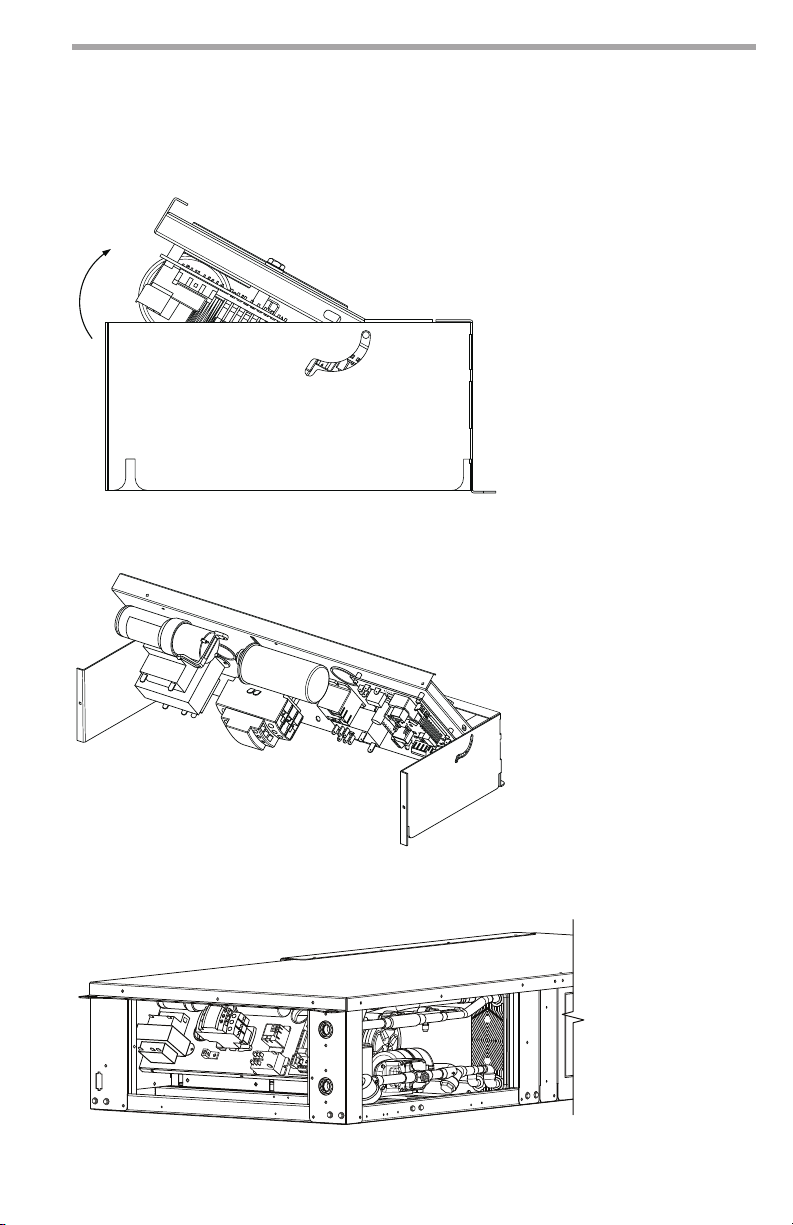
Unit Access
The TRL series is unique to the
ClimateMaster product line in the way
installers and service technicians’ interface
with the product. Traditionally for horizontal
products unit controls/electrical connections
are accessed from the unit’s front access
panel, blowers are accessed through the
side or back panel, and water/refrigerant
circuit repairs require the unit to be brought
down from the ceiling installation.
On TRL products the unit controls,
electrical components, water components/
circuit, the refrigeration components/
circuit, optional power disconnect, service
tool connection, drain pan, air coil, air lter,
and blower motor can be accessed from
the bottom of the unit (see Figures 7 and
8). This greatly increases the installers
and service technicians’ ability to access
and interface the water source heat pump
while it is installed in the ceiling.
The product is also designed to be
accessed in many of the traditional ways
as well. The unique control box design
ships from ClimateMaster facing down for
bottom access but can be ipped up in
the eld for front access. This allows those
who interface with the product to access
the unit controls either from the bottom
or from the front of the unit. See Figures 9
and 10 for details.
Alternatively, if the unit requires tabletop
service on the control box, the TRL
product is designed with a rotation feature
to allow installer or service technician to
interact with the control panel from the
front of the unit. The user will need to
remove the top and front access panels
from the unit, remove the 2 screws that
hold the control panel facing down, rotate
the control panel and lock it at 45 degrees
with the pivotal element on the right side
of the panel control support. See Figure
11 for details.
The complete blower assembly can be
slid down from the bottom of the unit.
The is a safety latch in place to prevent
the blower assembly from dropping
when the bottom blower access panel
is removed. Remove the screw and pull
back on the latch to slide the blower
assembly down. The assembly will rest
on a service rail where the technician may
service the motor or remove the whole
assembly by disconnecting one electrical
quick connector.
The TRL condensate drain pan can be
accessed for service or removal from
the bottom of the unit. After removing
the external condensate line connection,
remove the drain pan access panel. First,
remove the condensate sensor clip from
the pan and set it to the side. Next remove
the drain pan set screw located next to
the compressor side of the unit. Then
hold the drain pan and slide it towards
the back of the unit until the condensate
pan is pushed all the way against the back
access panel. Lastly, allow the opposite
side of the pan to drop down and then
slowly slide the drain pan down allowing
the drain pan nipple to be pulled through
the access panel opening with out
damaging the connection threads.
Bottom Service Access
• Controls
• Electrical Components
• Water Circuit/Components
• Refrigerant Circuit/Components
• Power Disconnect (optional - not
shown)
• Service Tool Connection
• Drain Pan
• Air Filter
• Air Coil
• Blower Motor Assembly

climatemaster.com 19
Tranquility®(TRL)Series
Rev.: November 11, 2021
CLIMATEMASTER WATER-SOURCE HEAT PUMPS
Unit Access, Cont’d.
CONTROLS & ELECTRICAL
BOTTOM SERVICE PANEL
BLOWER, AIR COIL, &
DRAIN PAN SERVICE PANEL
SUPPLY AIR
OPENINGS/
KNOCKOUTS
ADDITIONAL
SERVICE
PANEL
CONTROLS & ELECTRICAL
FRONT SERVICE PANEL
OPTIONAL POWER DISCONNECT
(NON-REMOVABLE PANEL
WHEN OPTION IS SELECTED)
SERVICE TOOL
CONNECTION
WATER & REFRIGERANT
SERVICE PANEL
WATER STRAINER
BLOWER, AIR COIL, &
DRAIN PAN SERVICE PANEL
WATER &
REFRIGERANT
SERVICE PANEL
CONTROLS & ELECTRICAL
BOTTOM SERVICE PANEL
Figure 7: ISO View (Left Return Conguration w/ Optional Power Disconnect Shown)
Figure 8: Bottom View (without Optional Power Disconnect Shown)
CLIMATEMASTER WATER-SOURCE HEAT PUMPS
Tranquility®(TRL)Series
Rev.: November 11, 2021
ClimateMaster Water-Source Heat Pumps
20
Unit Access, Cont’d.
Figure 9: Unit Control Box Rotation - Side View
Figure 10: Unit Control Box Rotation - Front ISO View
Figure 11: Unit Control Box Rotation - Table Top Service Position
This manual suits for next models
5
Table of contents
Popular Water Pump manuals by other brands


EINHELL
EINHELL GC-DW 900 N Original operating instructions

SFA
SFA SANICONDENS PRO installation instructions

KSB
KSB RDLO Series operating instructions

Grundfos
Grundfos SPK Series Installation and operating instructions

Teryair
Teryair SDP50PPT-BF Operation and maintenance guide

MAXIMATOR
MAXIMATOR GX35 operating instructions

bluefin
bluefin THBF701 Master Series installation manual

REED
REED EHTP500 Operator's manual

Wilo
Wilo Wilo-RainSystem AF Comfort MC 304 EM Installation and operating instructions

Gast
Gast SOA Series Operation & maintenance manual

Ingersoll-Rand
Ingersoll-Rand ARO 666300 C Series Operator's manual

Goulds Pumps
Goulds Pumps 3498 Installation, operation and maintenance manual