ClimateMaster THW Series Guide

Tranquility Water-to-Water (THW) Series
60Hz Models
Residential High Temperature
Water-to-Water
Geothermal Heat Pumps
(Heating Only)
Installation, Operation &
Maintenance Instructions
97B0063N01
Revision: 28 Aug., 2014J
THW Series
Table of Contents
Model Nomenclature 3
General Information 4
Physical Data 5
Dimensional Data 6
Installation 7
Load Plumbing Installation 7-8
Ground-Water Heat Pump Application 9
Water Quality Standards 10
Ground-Loop Heat Pump Application 11-12
Electrical - Line Voltage 13-14
Electrical - Low Voltage 15-16
Electrical - Controls 17-19
User Interface 20
Installer Interface 21
Wiring Diagram Matrix 22
Typical Wiring Diagrams 23-30
CXM Controls 31-33
Unit Commissioning 34
& Operating Conditions
Unit & System Checkout 35
Unit Start-Up Procedure 36
Preventive Maintenance 37
Warranty 38
Revision History 40

This page was intentionally left blank.

WARNING!
WARNING!
WARNING!
Model Nomenclature
Safety
Warnings, cautions and notices appear throughout this
manual. Read these items carefully before attempting any
installation, service, or troubleshooting of the equipment.
DANGER: Indicates an immediate hazardous situation, which
if not avoided will result in death or serious injury. DANGER
labels on unit access panels must be observed.
WARNING: Indicates a potentially hazardous situation, which
if not avoided could result in death or serious injury.
CAUTION: Indicates a potentially hazardous situation or an
unsafe practice, which if not avoided could result in minor or
moderate injury or product or property damage.
NOTICE: Notification of installation, operation or maintenance
information, which is important, but which is not hazard-
related.
WARNING! All refrigerant discharged from this unit must
be recovered WITHOUT EXCEPTION. Technicians must
follow industry accepted guidelines and all local, state,
and federal statutes for the recovery and disposal of
refrigerants. If a compressor is removed from this unit,
refrigerant circuit oil will remain in the compressor. To
avoid leakage of compressor oil, refrigerant lines of the
compressor must be sealed after it is removed.
WARNING! To avoid the release of refrigerant into the
atmosphere, the refrigerant circuit of this unit must be
serviced only by technicians who meet local, state, and
federal proficiency requirements.
3
Tranquility®High Temperature Water-to-Water (THW) Series
Rev.: 28 Aug., 2014
climatemaster.com
WARNING! Units are shipped with R-410A (EarthPure®)
refrigerant. The EarthPure®Application and Service Manual
should be read and understood before attempting to service
refrigerant circuits with R-410A.
T H W A010 WG 0 0 C S A S
1367
8
9
Series
W = Water-To-Water
Configuration
Unit Size
010
Revision Level
A= Current
Voltage
Controls
0 = Residential Standard
Cabinet Insulation
Domestic Hot Water Heating Options
C = Copper Source & Braze Plate Load
Source & Load Water Coil Options
N = Cupro-nickel Source & Braze Plate Load
A= None
Hydronic Options
B = Load Pump w/Expansion Tank
S = Standard
0 = None
Paint Options
S = Stainless Steel & Pewter (Black)
1 = DHW Option w/sec heat exchanger and pump*
C = Load Pump & Source Pump(s)
w/Expansion Tanks
W = Standard
Y = Standard With VSFP
G = 208-230/60/1
Rev.: 4 Sept., 2013B
24513
10 11 12 1514
* When digit 11 is ‘1’, digit 14 can not be ‘A’.
WARNING! Polyolester Oil, commonly known as POE
oil, is a synthetic oil used in many refrigeration systems
including those with HFC-410A refrigerant. POE oil, if it
ever comes in contact with PVC or CPVC piping, may
cause failure of the PVC/CPVC. PVC/CPVC piping should
never be used as supply or return water piping with water
source heat pump products containing HFC-410A as
system failures and property damage may result.
WARNING!

Inspection
Upon receipt of the equipment, carefully check the shipment
against the bill of lading. Make sure all units have been
received. Inspect the carton or crating of each unit, and
inspect each unit for damage. Assure the carrier makes
proper notation of any shortages or damage on all copies of
the freight bill and completes a common carrier inspection
report. Concealed damage not discovered during unloading
must be reported to the carrier within 15 days of receipt of
shipment. If not filed within 15 days, the freight company can
deny the claim without recourse. Note: It is the responsibility
of the purchaser to file all necessary claims with the carrier.
Notify your equipment supplier of all damage within fifteen
(15) days of shipment.
Storage
Equipment should be stored in its shipping carton in a clean,
dry area. Store units in an upright position at all times. Stack
units a maximum of 3 units high.
Unit Protection
Cover units on the job site with either shipping cartons, vinyl
film, or an equivalent protective covering. Cap the open
ends of pipes stored on the job site. In areas where painting,
plastering, and/or spraying has not been completed, all
due precautions must be taken to avoid physical damage
to the units and contamination by foreign material. Physical
damage and contamination may prevent proper start-up and
may result in costly equipment clean-up.
Examine all pipes, fittings, and valves before installing any of
the system components. Remove any dirt or trash found in
or on these components.
Pre-Installation
Installation, Operation, and Maintenance instructions are
provided with each unit.. The installation site chosen should
include adequate service clearance around the unit. Before
unit start-up, read all manuals and become familiar with the
unit and its operation. Thoroughly check the system before
operation.
Prepare units for installation as follows:
1. Compare the electrical data on the unit nameplate with
ordering and shipping information to verify that the
correct unit has been shipped.
2. Keep the cabinet covered with the shipping carton until
installation is complete and all plastering, painting, etc.
is finished.
3. Verify refrigerant tubing is free of kinks or dents and that
it does not touch other unit components.
4. Inspect all electrical connections. Connections must be
clean and tight at the terminals.
5. Locate and verify any HWG or other accessory sensors
located in the compressor section.
CAUTION!
CAUTION!
General Information
CAUTION! DO NOT store or install units in corrosive
environments or in locations subject to temperature or
humidity extremes (e.g., attics, garages, rooftops, etc.).
Corrosive conditions and high temperature or humidity
can significantly reduce performance, reliability, and
service life. Always move and store units in an upright
position. Tilting units on their sides may cause equipment
damage.
CAUTION! CUT HAZARD - Failure to follow this caution
may result in personal injury. Sheet metal parts may have
sharp edges or burrs. Use care and wear appropriate
protective clothing, safety glasses and gloves when
handling parts and servicing heat pumps.
Tranquility®High Temperature Water-to-Water (THW) Series
Rev.: 28 Aug., 2014
4Geothermal Heating and Cooling

Physical Data
Model 010
Compressor (qty) 1
Factory Charge R410A (oz) [kg] 88 [2.50]
Indoor/Load Water Connection Size
FPT (in) 1
Outdoor/Source Water Connection Size
FPT (in) 1
Domestic Hot Water Connection Size
FPT (in) 3/4
Maximum Working Pressure (Water Side)
Base Unit (PSIG) [kPa] 500 [3445]
DHW Option (PSIG) [kPa] 145 [999]
Internal Source Pump*
w/Expansion Tank (PSIG) [kPa] 45 [310]
Internal Load Pump*
w/Expansion Tank (PSIG) [kPa] 45 [310]
Weight - Operating, (lbs) [kg] 455 [207]
Weight - Packaged, (lbs) [kg] 470 [214]
Dual isolation compressor mounting
Balanced Port Expansion Valve (TXV)
Insulated Source and Load Water Coils
*Does not apply to DHW potable water circuit
5
Tranquility®High Temperature Water-to-Water (THW) Series
Rev.: 28 Aug., 2014
climatemaster.com
Table 1: Physical Data

Dimensional Data
Notes:
1. Front, Side, and Top access is preferred for service access.
However, all components may be serviced from the front and
Top access panels if side access is not available.
2. While clear access to all removable panels is not required,
installer should take care to comply with all building codes
and allow adequate clearance for future field service.
1.9” [4.9cm]
2.1” [5.3cm]
Model
Overall Cabinet Water Connections Electric Access Plugs
123456
A
Depth
B
Width
C
Height
D
Source
(Outdoor)
Water In
E
Source
(Outdoor)
Water Out
F
Load
(Indoor)
Water In
G
DHW
Water Out
H
Load
(Indoor)
Water Out
J
DHW
Water In
K
Low
Voltage
L
Low
Voltage
M
Power
Supply
010
in. 26.8 25.6 48.9 3.4 8.1 22.3 11.3 17.7 14.4 33.6 35.6 38
cm. 68.1 65.1 124.2 8.6 20.6 56.6 28.7 45 36.6 85.3 90.4 96.5
Tranquility®High Temperature Water-to-Water (THW) Series
Rev.: 28 Aug., 2014
6Geothermal Heating and Cooling

Installation
Unit Location
These units are not designed for outdoor installation. Locate
the unit in an INDOOR area that allows enough space for
service personnel to perform typical maintenance or repairs.
The installation of water source heat pump units and all
associated components, parts and accessories which
make up the installation shall be in accordance with
the regulations of ALL authorities having jurisdiction
and MUST conform to all applicable codes. It is the
responsibility of the Installing Contractor to determine
and comply with ALL applicable codes and regulations.
Locate the unit in an indoor area that allows easy removal of
access panels, and has enough space for service personnel
to perform maintenance or repair. Provide sufficient room to
make water and electrical connections. Any access panel
screws that would be difficult to remove after the unit is
installed should be removed prior to setting the unit. These
units are not approved for outdoor installation and, therefore,
must be installed inside the structure being conditioned.
Do not locate in areas where ambient conditions are not
maintained within 40-100°F [4-38°C] and up to 75% relative
humidity.
The applications are too varied to describe in this
document, however some basic guidelines will be
presented. All plumbing should conform to local codes
and consider the following:
Wide temperature variation applications such as
heating/cooling coils
- Employ piping materials that are rated for the
maximum temperature and pressure combination.
- Insure load water flow in high temperature heating
applications is at least 3 gpm per ton [3.2 l/m per
kW] to improve performance and reduce nuisance
high pressure faults.
- DO NOT employ plastic to metal threaded joints
- Utilize a pressure tank and air separator vent
system to equalize pressure and remove air.
Swimming Pool Hot Tub Applications
- Recommended application includes a brazed plate
heat exchanger to isolate pool water from the unit
heat exchanger.
Potable Water Applications
- Insure load water flow in high temperature heating
applications is at least 3 gpm per ton [3.2 l/m per
kW] to improve performance and reduce nuisance
high pressure faults.
- DHW option includes an internal secondary brazed
plate heat exchanger and bronze circulating pump.
LOAD PLUMBING INSTALLATION
Figure 1a: THW Internal Piping
7
Tranquility®High Temperature Water-to-Water (THW) Series
Rev.: 28 Aug., 2014
climatemaster.com
Load Piping Connections
Load piping connections are designated ‘Load Water In
andOut’for the radiant heating system piping, and ‘DHW
WaterInandOut’(optional)forconnectiontothedomestic
hot water piping.
THW Unit Load Plumbing

Load Plumbing Installation
Water Heater
Heating
Buffer Tank
NOTES:
1. Place air vent at the highest point in the system.
2. Thermistors should be installed in an immersion well.
Locate thermistor in the bottom half of the tank.
3. P/T (pressure/temperature) ports are internal for THW
units on load and source connections.
4. Other components (additional ball valves, unions, etc.)
may be required for ease of service. This drawing
shows only minimum requirements. Your specific
installation will dictate final component selections.
5. Buffer tank must be approved as a heating vessel.
7. Local code supercedes any piping arrangements or
components shown on this drawing.
To/From
Radiant Floor,
Radiator,
Baseboard,
or Fan Coil
Heating System
HC
HC
THW
Unit
OUT
DHW IN
DHW
Thermistor
Note 2
Thermistor
Note 2
HTG
OUT HTG
IN
Figure 1b: THW with DHW Internal Piping
Tranquility®High Temperature Water-to-Water (THW) Series
Rev.: 28 Aug., 2014
8Geothermal Heating and Cooling
Figure 2: THW Typical Load Piping

Typical open loop piping is shown in Figure 3. Shut off valves
should be included in case of servicing. Boiler drains or other
valves should be ‘tee’d’ into the line to allow acid flushing of
just the heat exchanger. Pressure temperature plugs should
be used so that flow and temperature can be measured.
Supply and return water piping should be limited to copper,
HPDE, or other acceptable high temperature material. Note
that PVC or CPVC material is not recommended as they
are not compatible with the polyolester oil used in HFC-
410A products. Water quantity should be plentiful and of
good quality. Consult Table 2 for water quality guidelines.
The unit can be ordered with either a copper or cupro-nickel
water heat exchanger. Copper is recommended for closed
loop systems and open loop ground water systems that are
not high in mineral content or corrosiveness. In conditions
anticipating heavy scale formation or in brackish water, a
cupro-nickel heat exchanger is recommended. In ground
water situations where scaling could be heavy or where
biological growth such as iron bacteria will be present, a
closed loop system is recommended. Heat exchanger coils
may over time lose heat exchange capabilities due to a build
up of mineral deposits inside. These can be cleaned only by
a qualified service mechanic as acid and special pumping
equipment are required.
Expansion Tank and Pump
Use a closed, bladder-type expansion tank to minimize
mineral formation due to air exposure. The expansion tank
should be sized to handle at least one minute run time
of the pump to prevent premature pump failure using its
drawdown capacity rating. The pump should be sized to
the home’s domestic water load (5-9 gpm [19-34 l/m]) plus
the heat pump water load. Discharge water from the unit is
not contaminated in any manner and can be disposed of in
various ways depending on local building codes; i.e. recharge
well, storm sewer, drain field, adjacent stream or pond, etc.
Most local codes forbid the use of sanitary sewer for disposal.
Consult your local building and zoning department to assure
compliance in your area.
Water Control Valve
Note the placement of the water control valve. Always
maintain water pressure in the heat exchanger by placing
water control valves at the outlet of the unit to prevent mineral
precipitation. Pilot operated or Taco slow closing valve’s
solenoid valves are recommended to reduce water hammer.
If water hammer persists, a mini-expansion tank can be
mounted on the piping to help absorb the excess hammer
shock. Insure that the total ‘VA’ draw of the valve can be
supplied by the unit transformer. For instance the Taco slow
closing valve can draw up to 35VA. This can overload smaller
40 or 50 VA transformers depending on the other controls
employed. A typical pilot operated solenoid valve draws
approximately 15VA. Note the special wiring diagram of the
AVM valve (Figure 8).
Flow Regulation
Flow regulation can be accomplished by two methods. First,
most water control valves have a built in flow adjustment.
By measuring the pressure drop through the unit heat
exchanger, flow rate can be determined and compared
to Table 8. Simply adjust the water control valve until the
desired flow is achieved. Secondly, a flow control device may
be installed. The devices are typically an orifice of plastic
material that is designed to allow a specified flow rate. These
are mounted on the outlet of the water control valve. On
occasion, these valves can produce a velocity noise that
can be reduced by applying some back pressure. This is
accomplished by slightly closing the leaving isolation valve of
the well water setup.
Low Temperature Cutout
The water low temperature cutout setpoint should be
activated to avoid freeze damage to the unit. Consult the
low temperature cutout section of the controls description for
instructions.
CAUTION!
CAUTION! Many units are installed with a factory or field
supplied manual or electric shut-offvalve. DAMAGE
WILL OCCUR if shut-offvalve is closed during unit
operation. A high pressure switch must be installed on the
heat pump side of any field provided shut-offvalves and
connected to the heat pump controls in series with the
built-in refrigerant circuit high pressure switch to disable
compressor operation if water pressure exceeds pressure
switch setting. The field installed high pressure switch shall
have a cut-out pressure of 235 psig [1620 kPa] and a cut-in
pressure of 190 psig [1310 kPa]. This pressure switch can
be ordered with a 1/4” internal flare connection as part
number 39B0005N01.
CAUTION!
CAUTION! Refrigerant pressure activated water regulating
valves should never be used with this equipment.
Ground-Water Heat Pump Systems
9
Tranquility®High Temperature Water-to-Water (THW) Series
Rev.: 28 Aug., 2014
climatemaster.com

Table 2: Water Quality Standards
Figure 3: Typical Open Loop/ Well Application
Water Quality
Parameter HX
Material Closed
Recirculating Open Loop and Recirculating Well
Scaling Potential - Primary Measurement
pH/Calcium Hardness All -pH < 7.5 and Ca Hardness <100ppm
Method
Index Limits for Probable Scaling Situations -
(Operation outside these limits is not recommended)
Ryznar All - 6.0 - 7.5
Stability Index If >7.5 minimize steel pipe use.
Langelier All --0.5 to +0.5
Saturation Index If <-0.5 minimize steel pipe use. Based upon 66°C HWG and
Direct well, 29°C Indirect Well HX
Iron Fouling
Iron Fe 2+ (Ferrous) All -<0.2 ppm (Ferrous)
(Bacterial Iron potential) If Fe2+ (ferrous)>0.2 ppm with pH 6 - 8, O2<5 ppm check for iron bacteria.
Iron Fouling All -<0.5 ppm of Oxygen
Above this level deposition will occur.
Corrosion Prevention
pH All 6 - 8.5 6 - 8.5
Monitor/treat as
needed Minimize steel pipe below 7 and no open tanks with pH <8
Hydrogen Sulfide (H
2
S) All - <0.5 ppm
At H
2
S>0.2 ppm, avoid use of copper and copper nickel piping or HX's.
Rotten egg smell appears at 0.5 ppm level.
Copper alloy (bronze or brass) cast components are OK to <0.5 ppm.
Ammonia ion as hydroxide, chloride,
nitrate and sulfate compounds All -<0.5 ppm
Maximum
Maximum Allowable at maximum water temperature.
Chloride Levels
10$C24$C38
C
Copper
Cupronickel -<20ppm NR NR
-<150 ppm NR NR
304 SS-<400 ppm <250 ppm <150 ppm
316 SS-<1000 ppm <550 ppm < 375 ppm
Titanium ->1000 ppm >550 ppm >375 ppm
Erosion and Clogging
Particulate Size and
Erosion All
<10 ppm of particles
and a maximum
velocity of 1.8 m/s
Filtered for maximum
841 micron [0.84 mm,
20 mesh] size.
<10 ppm (<1 ppm "sandfree” for reinjection) of particles and a maximum
velocity of 1.8 m/s. Filtered for maximum 841 micron 0.84 mm,
20 mesh] size. Any particulate that is not removed can potentially
clog components.
Notes:
Rev.: 5/6/2014 S
• NR - Application not recommended.
•
""
No design Maximum
• Closed Recirculating system is identified by a closed pressurized piping system.
• Recirculating open wells should observe the open recirculating design considerations.
Above the given limits, scaling is likely to occur. Scaling indexes should be calculated using the limits below
Scaling indexes should be calculated at 66°C for direct use and HWG applications, and at 32°C for indirect HX use.
A monitoring plan should be implemented.
The ClimateMaster Water Quality Table provides water quality requirements for ClimateMaster coaxial heat exchangers. The water should be evaluated by an
independent testing facility comparing to this Table and when properties are outside of these requirements, an external secondary heat exchanger must be used to
isolate the heat pump heat exchanger from the unsuitable water. Failure to do so will void the warranty for the coaxial heat exchanger and any other components
damaged by a leak.
Ground-Water Heat Pump Systems
THW
NOTES:
1. P/T (pressure/temperature) ports are internal for THW
series units.
2. Other components (additional ball valves, unions, etc.)
may be required for ease of service. This drawing
shows only minimum requirements. Your specific
installation will dictate final component selections.
3. Local code supercedes any piping arrangements or
components shown on this drawing.
Sound absorbing pad
Source HX
(coaxial)
IN OUT
P/T port
To proper discharge location
S
From pressure tank
Strainer (optional)
Shut-off valve
Boiler drain (for flushing)
Water control valve
High Pressure Switch
Flow regulator
Tranquility®High Temperature Water-to-Water (THW) Series
Rev.: 28 Aug., 2014
10 Geothermal Heating and Cooling

Piping Installation
The typical closed loop ground source system is shown in
Figure 4. All earth loop piping materials should be limited to
only polyethylene fusion in inground sections of the loop.
Galvanized or steel fitting should not be used at any time
due to their tendency to corrode. All plastic to metal threaded
fittings should be avoided due to their potential to leak in
earth coupled applications and a flanged fitting substituted.
P/T plugs should be used so that flow can be measured
using the pressure drop of the unit heat exchanger in lieu of
other flow measurement means. Earth loop temperatures can
range between 25-110°F [-3.9 - 43.3°C]. Upon completion
of the ground loop piping, pressure test the loop to assure a
leak free system. Horizontal Systems: test individual loops as
installed. Test entire system when all loops are assembled.
Vertical U-Bends and Pond Loop Systems: test vertical
U-bends and pond loop assemblies prior to installation with a
hydrostatic test pressure of at least 100 psi [689 kPa].
Flushing the Earth Loop
Once piping is completed between the unit, flow center and
the ground loop (Figure 4), final purging and charging of the
loop is needed. A flush cart (at least a 1.5 hp [1.1 kW] pump)
is needed to achieve adequate flow velocity in the loop to
purge air and dirt particles from the loop itself. An antifreeze
solution is used in most areas to prevent freezing. All air and
debris must be removed from the earth loop piping system
before operation. Flush the loop with a high volume of water
at a high velocity (2 fps [0.6 m/s] in all piping) both directions.
The steps below must be followed for proper flushing. Fill
loop with water from a garden hose through flush cart before
using flush cart pump to ensure an even fill. Once full, do
not allow the water level in the flush cart tank to drop below
the pump inlet line or air can be pumped back out to the
earth loop. Try to maintain a fluid level in the tank above the
return tee so that air can not be continuously mixed back
into the fluid. 50 psi [345 kPa] surges can be used to help
purge air pockets by simply shutting off the return valve going
into the flush cart reservoir. This ‘dead heads’ the pump to
50 psi [345 kPa]. To dead head the pump until maximum
pumping pressure is reached, open the valve back up and
a pressure surge will be sent through the loop to help purge
air pockets from the piping system. Notice the drop in fluid
level in the flush cart tank. If air is purged from the system,
the level will drop only 1-2 [25-50mm] inches in a 10”
[254mm] diameter PVC flush tank (about a half gallon)
since liquids are incompressible. If the level drops more
than this, flushing should continue since air is still being
compressed in the loop fluid. Do this a number of times.
When the fluid level drops less than 1-2” [25-50mm] in a 10”
[254mm] diameter tank the flow can be reversed. Finally the
dead head test should be checked again for an indication of
air in the loop. This fluid level drop is your only indication
of air in the loop.
Table 3: Approximate Fluid Volume (gal.) per 100' of Pipe
Table 4: Antifreeze Percentages by Volume
Fluid Volume (gal [liters] per 100’ [30 meters) Pipe)
Pipe Size Volume (gal) [liters]
Copper
1” 4.1 [15.3]
1.25” 6.4 [23.8]
2.5” 9.2 [34.3]
Rubber Hose 1” 3.9 [14.6]
Polyethylene
3/4” IPS SDR11 2.8 [10.4]
1” iPS SDR11 4.5 [16.7]
1.25” IPS SDR11 8.0 [29.8]
1.5” IPS SDR11 10.9 [40.7]
2” IPS SDR11 18.0 [67.0]
1.25” IPS SCH40 8.3 [30.9]
1.5” IPS SCH40 10.9 [40.7]
2” IPS SCH40 17.0 [63.4]
Unit Heat Exchanger Typical 1.0 [3.8]
Flush Cart Tank 10” Dia x 3ft tall
[254mm x 91.4cm tall] 10 [37.9]
Ground-Loop Heat Pump Applications
Type
Minimum Temperature
for Low Temperature Protection
10°F
[-12.2°C]
15°F
[-9.4°C]
20°F
[-6.7°C]
25°F
[-3.9°C]
Methanol
Propylene Glycol
Ethanol*
21%
29%
23%
17%
24%
20%
13%
18%
16%
8%
12%
11%
* Must not be denatured with any petroleum based product
11
Tranquility®High Temperature Water-to-Water (THW) Series
Rev.: 28 Aug., 2014
climatemaster.com

Figure 4: Typical Earth Loop Connection.
Antifreeze may be added before, during, or after the flushing
procedure. However, depending upon which time is chosen,
antifreeze could be wasted when emptying the flush cart
tank. See antifreeze section for more details. Loop static
pressure will fluctuate with the seasons. Pressures will be
higher in the winter months than during the cooling season.
This fluctuation is normal and should be considered when
charging the system initially. Run the unit in either heating
or cooling for a number of minutes to condition the loop to
a homogenous temperature. This is a good time for tool
cleanup, piping insulation etc. Then final flush and pressurize
the loop to a static pressure of 40-50 psi [275-345 kPa]
(winter) 15-20 psi [100-138 kPa] (summer).
After pressurization, be sure to remove the plug in the end
of the Grundfos loop pump motor(s) to allow trapped air to
be discharged and to insure the motor housing has been
flooded. This is not required for Taco circulators. Insure the
loop flow center provides adequate flow through the unit
by checking pressure drop across the heat exchanger and
comparing it to the figures shown in Table 8.
Antifreeze
In areas where minimum entering loop temperatures drop
below 40°F [4.4°C] or where piping will be routed through
areas subject to freezing, antifreeze is needed. Alcohols and
glycols are commonly used as antifreezes, however your
local territory manager should be consulted for the antifreeze
best suited to your area. Low temperature protection should
be maintained to 15°F [-9.4°C] below the lowest expected
entering loop temperature. For example, if 30°F [-1.1°C]
is the minimum expected entering loop temperature, the
leaving loop temperature would be 25-22°F [-3.9 to -5.6°C]
and low temperature protection should be at 15°F [-9.4°C]
(30°F-15°F=15°F). All alcohols should be premixed and
pumped from a reservoir outside of the building when
possible or introduced under water level to prevent fuming.
Initially calculate the total volume of fluid in the piping system
using Table 3. Then use the percentage by volume shown in
Table 4 for the amount of antifreeze. Antifreeze concentration
should be checked from a well mixed sample using a
hydrometer to measure specific gravity.
Low Water Temperature Cut-Out Setting
When an antifreeze is selected the low temperature limit
setpoint should be switched to the lower setting to avoid
nuisance faults. Consult Low Water Temperature Cut-Out
Setting in the controls section for more information.
Ground-Loop Heat Pump Applications
7R)URP*URXQG/RRS
7+:
,1 287
127(6
37SUHVVXUHWHPSHUDWXUHSRUWVDUHLQWHUQDOIRU7+:
VHULHVXQLWV
6RXUFHZDWHUSLSLQJPXVWEHLQVXODWHGIRUFORVHGORRS
LQVWDOODWLRQV
2WKHUFRPSRQHQWVDGGLWLRQDOEDOOYDOYHVXQLRQVHWF
PD\EHUHTXLUHGIRUHDVHRIVHUYLFH7KLVGUDZLQJ
VKRZVRQO\PLQLPXPUHTXLUHPHQWV<RXUVSHFLILF
LQVWDOODWLRQZLOOGLFWDWHILQDOFRPSRQHQWVHOHFWLRQV
/RFDOFRGHVXSHUFHGHVDQ\SLSLQJDUUDQJHPHQWVRU
FRPSRQHQWVVKRZQRQWKLVGUDZLQJ
)ORZ&RQWUROOHU
37SRUW
6RXQGDEVRUELQJSDG
2SWLRQDO)ORZ&RQWUROOHU
IRUXQLWVQRWHTXLSSHG
ZLWKDQLQWHUQDOSXPS
Tranquility®High Temperature Water-to-Water (THW) Series
Rev.: 28 Aug., 2014
12 Geothermal Heating and Cooling

Table 5: Electrical Data
WARNING!
CAUTION!
All field installed wiring, including electrical ground, must
comply with the National Electrical Code as well as all
applicable local codes.
Refer to the unit wiring diagrams for fuse sizes and a
schematic of the field connections which must be made by
the installing (or electrical) contractor.
Consult the unit wiring diagram located on the inside of the
compressor access panel to ensure proper electrical hookup.
All final electrical connections must be made with a length of
flexible conduit to minimize vibration and sound transmission
to the building.
208 Volt Operation
All 208-240 Volt units are factory wired for 240 Volt. The
transformers may be switched to 208V operation as illustrated
on the wiring diagram. By switching the Red (208V) and the
Orange (240V) at the terminal.
Electrical - LineVoltage
CAUTION! Use only copper conductors for field installed
electrical wiring. Unit terminals are not designed to accept
other types of conductors.
WARNING! To avoid possible injury or death due to
electrical shock, open the power supply disconnect switch
and secure it in an open position during installation.
13
Tranquility®High Temperature Water-to-Water (THW) Series
Rev.: 28 Aug., 2014
climatemaster.com
Units with DHW Option
Model Voltage
Code Voltage Min/Max
Voltage
Compressor *Load
Pump
FLA
*Source
Pump
FLA
ISBP
Pump
FLA
Total
Unit
FLA
Min
Circuit
Amps
Max
Fuse
HACR
Qty RLA LRA
THW010 G 208-230/60/1 197/254 1 20.7 81 1.07 - 1.07 22.8 28 45
1.07 1.07 1.07 23.9 29.1 45
Standard (No DHW)
Model Voltage
Code Voltage Min/Max
Voltage
Compressor *Load
Pump
FLA
*Source
Pump
FLA
Total
Unit
FLA
Min
Circuit
Amps
Max
Fuse
HACR
Qty RLA LRA
THW010 G 208-230/60/1 197/254 1 20.7 81
- - 20.7 25.9 45
1.07 - 21.8 26.9 45
1.07 1.07 22.8 28 45
*Denotes optional items. Consult unit data plate if configuration is unknown.
General Line Voltage Wiring
Be sure the available power is the same voltage and phase as
that shown on the unit serial plate. Line and low voltage wiring
must be done in accordance with local codes or the National
Electric Code, whichever is applicable.
THW Power Connection
Line voltage connection is made by connecting the incoming
line voltage wires to the power block as shown in Figure 5.
Consult Table 5 or unit data plate for correct fuse size.

Electrical - LineVoltage
Field Low Voltage Wiring Field Line Voltage Wiring
Tranquility®High Temperature Water-to-Water (THW) Series
Rev.: 28 Aug., 2014
14 Geothermal Heating and Cooling
Figure 5: THW Line and Low Voltage

LT1
LT2
Figure 7: Accessory Wiring
Figure 6: Changing FP1-Low Water Temperature Cutout
Setpoint
JW3-FP1 jumper
should be clipped
when antifreeze
is used.
CXM Board
1. The valve will remain open during a unit lockout.
2.
The valve will draw approximately 25-35 VA through the “Y”
signal of the thermostat.
CXM
Board
Electrical - LowVoltage
"A" has been provided to control accessory devices, such as
water valves, electronic air cleaners, humidifiers, etc. Note:
This terminal should be used only with 24 Volt signals
and not line voltage signals. This signal operates with the
compressor contactor. See Figure 7 or the wiring schematic
for details.
15
Tranquility®High Temperature Water-to-Water (THW) Series
Rev.: 28 Aug., 2014
climatemaster.com
Low Voltage Connections
The thermistors (sensors) and other low voltage wiring
should be connected to the 12 position terminal strip in the
THW control box. See figure 4 and unit wiring diagram for
details.
Thermistors (one each) for the buffer tank, outdoor air, and
DHW storage tank (if equipped with the DHW option) are
coiled and shipped loose in the unit.
Low Water Temperature Cutout - FP1
The CXM/DXM control allows the field selection of source fluid
low temperature cutout points. The factory setting of FP1 is
set for water (30°F [-1.1°C]). In cold temperature applications
jumper JW3 (FP1- antifreeze 10°F [-12.2°C]) should be clipped
as shown in Figure 6 to change the setting to 10°F [-12.2°C], a
more suitable temperature when using antifreezes.
Accessory Connections
A terminal paralleling the compressor contactor coil has
been provided on the CXM/DXM control of the THW unit.
Water Solenoid Valves
Figures 8a and 8b illustrate a typical slow closing water
control valve wiring. A slow closing valve may be required
to prevent water hammer. When using an AVMB -Taco
Slow Closing valves on THW Series equipment Figure 8a
wiring should be utilized. The valve takes approximately
60 seconds to open (very little water will flow before 45
seconds) and it activates the compressor only after the
valve is completely opened (by closing its end switch). Only
relay or triac based electronic thermostats should be used
with the AVMB valve. When wired as shown, the valve will
operate properly with the following notations:

Figure 8a: Well Water AVMB Valve Wiring CAUTION!
CAUTION! Many units are installed with a factory or field
supplied manual or electric shut-offvalve. DAMAGE
WILL OCCUR if shut-offvalve is closed during unit
operation. A high pressure switch must be installed on the
heat pump side of any field provided shut-offvalves and
connected to the heat pump controls in series with the
built-in refrigerant circuit high pressure switch to disable
compressor operation if water pressure exceeds pressure
switch setting. The field installed high pressure switch shall
have a cut-out pressure of 235 psig [1620 kPa] and a cut-in
pressure of 190 psig [1310 kPa]. This pressure switch can
be ordered with a 1/4” internal flare connection as part
number 39B0005N01.
CAUTION!
CAUTION! Refrigerant pressure activated water regulating
valves should never be used with this equipment.
Figure 8b: Taco SBV Valve Wiring
R
CXM Board*
MPC*
Y
123
Y1
AVMB
Taco Valve
Heater Switch
*Valve must be wired in between the CXM and MPC boards. Remove the yellow
wire from the CXM board and connect it to terminal 2 on the valve. Add a new
wire from terminal 3 to the Y terminal at the CXM board, and a jumper wire from
terminal 1 to terminal R at the CXM board as shown above.
*Valve must be wired in between the CXM and MPC boards. Remove the yellow
wire from the CXM board and connect it to the w/y terminal on the valve. Add a
new wire from the end switch (bottom connection) to the the Y terminal at the
CXM board, and a jumper wire from the w/y terminal to the other side (top
connection) of the end switch as shown above.
Taco SBV Valve
Y1
MPC*
C
CXM
Board
Y*
Electrical - LowVoltage
Tranquility®High Temperature Water-to-Water (THW) Series
Rev.: 28 Aug., 2014
16 Geothermal Heating and Cooling
WARNING! Polyolester Oil, commonly known as POE
oil, is a synthetic oil used in many refrigeration systems
including those with HFC-410A refrigerant. POE oil, if it
ever comes in contact with PVC or CPVC piping, may
cause failure of the PVC/CPVC. PVC/CPVC piping should
never be used as supply or return water piping with water
source heat pump products containing HFC-410A as
system failures and property damage may result.
WARNING!

Arrow Keys
Select Key
CAUTION!
Electrical - Controls
17
Tranquility®High Temperature Water-to-Water (THW) Series
Rev.: 28 Aug., 2014
climatemaster.com
Controls
User interface: Figure 9 shows the factory installed and
wired panel-mounted user interface for customizing the
MPC programming. A large dot-matrix style 2” x 2” [5 x 5
cm] back-lit display is controlled by four arrow keys and a
select key. The main screen, as shown in figure 10, displays
current outdoor and water temperatures, and allows the
user to change settings by selecting one of the menus from
the bottom of the screen (see figure 12 THW User Interface
Menu). A special installer set up mode allows the technician
to change some of the default MPC parameters. The installer
menu may only be accessed when the unit is placed in the
off mode. Holding the up and down buttons at the same time
will cause the interface to enter the installer setup mode.
See figure 13 (interface installer menu) The user interface
includes a time schedule for DHW generation, Fahrenheit/
Celsius selection, vacation mode for DHW, and other user
preference options.
Figure 9: THW User Interface
Figure 10: THW User Interface Main Screen
THW Series Control Features
The advantage of a programmable controller, as outlined
above, is the ability to integrate complex decision-making
tasks with the standard heat pump (CXM) controls and
communicate with a user interface. Below is a list of
standard features that are included in the THW series
controls.
Outdoor temperature reset: The heat pump capacity and
water temperature delivery to the heating system must be
designed for local weather conditions, usually at the 99.6%
outdoor temperature. Therefore, 99.6% of the heating
season, the heating load is less than it is at design conditions.
As the outdoor temperature decreases, the heat loss of
the structure increases, which requires more capacity from
the heating system. If the water temperature is reduced
as the outdoor air temperature increases (and vise-versa),
the heat pump operates at higher COP most of the year.
The MPC has a built in algorithm that adjusts the buffer
tank temperature based upon outdoor air temperature to
maximize efficiency and comfort. Temperature settings may
be adjusted at the user interface if factory defaults are not
sufficient.
The base setpoint for energizing the compressor in the
heating mode is determined by subtracting one-half the
heating differential value (HTD) from the buffer tank heating
temperature setpoint. The HTD is the differential used for
controlling setpoint. For example, if the buffer tank setpoint
is 100°F [38°C], and the HTD is 6°F [3°C], the compressor
will be energized at 97°F [36°C] and will be turned off at
103°F [39°C]. The HTD is the difference between the
compressor “call” (97°F [36°C]) and the “satisfied” (103°F
[39°C]) temperature. The buffer tank temperature may
then be reduced by the outdoor temperature reset function,
depending on the current outdoor air temperature (OAT)
value.
The valid range for the buffer tank heating setpoint is
70-140°F [21-60°C], with a default value of 100°F [38°C]. The
valid range for the heating differential value (HTD) is 4-20°F
[2-11°C], adjustable in 2°F [1°C] increments, with a default
value of 6°F [3°C].
CAUTION: Maximum leaving water temperature of the
THW series equipment is 145°F [63°C]. For domestic
hot water tank temperatures or heating buffer tank
temperatures above 130°F [54°C], pump and pipe sizing is
critical to insure that the flow rate through the heat pump
is sufficient to maintain leaving water temperatures below
the maximum temperature, and to provide water flow
rates within the ranges shown in the performance section
of this manual.

10
15
20
25
30
35
40
45
50
55
30 25 20 15 10 5 0 -5 -10 -15 -20 -25 -30
Outdoor Temperature, °C [°F]
Buffer Tank Temperature, °C [°F]
[50]
[59]
[68]
[77]
[86]
[95]
[104]
[113]
[122]
[131]
[86] [77] [68] [59] [50] [41] [32] [23] [14] [5] [-4] [-13] [-22]
Maximum
Buffer Tank
Temperature
52ºC [126ºF]
20ºC [68ºF]
Minimum
Buffer Tank
Temperature
Building
Balance
Point
Temperature
Outdoor
Design
Temperature
Figure 11: Example Outdoor Temperature Reset
Table 6: Buffer Tank Interface Inputs
Setting Description Range Default
Buffer Tank Set Point 70-140°F [21-60°C} 100°F [38°C]
Buffer Tank Deadband 4-20°F [2-11°C] 6°F [3°C]
Outdoor Design Temp -40-50°F [-40-10°C] 0°F [-18°C]
Maximum Design
Water Temp 80-140°F [27-60°C] 130°F [54°C]
Minimum Design
Water Temp 70-120°F [21-49°C] 70°F [21°C]
Building Balance
Point Temp 50-70°F [10-21°C] 60°F [16°C]
The maximum design water temperature must be equal the buffer
tank setpoint. The buffer tank setpoint will override the maximum
design temperature if they are entered with different values.
Electrical - Controls
Tranquility®High Temperature Water-to-Water (THW) Series
Rev.: 28 Aug., 2014
18 Geothermal Heating and Cooling
There are four outdoor reset variables used for reducing the
buffer tank setpoint. The outdoor design temperature (ODT)
is the OAT above which setpoint reduction begins. The
valid range for ODT is –40°F to 50°F [-40°C to 10°C], with
a default value of 0°F [-18°C]. The maximum design buffer
tank temperature (MaxBT) is the maximum desired buffer
tank setpoint at the outdoor design temperature. The valid
range for MaxBT is 80-140°F [27-60°C], with a default value
of 130°F [54°C]. The building balance point temperature
(the temperature at which heating is no longer needed) is
the OAT at which maximum setpoint (MaxBT) reduction will
occur. The valid range for building balance point is 50-70°F
[10-21°C], with a default value of 60°F [16°F]. The minimum
design water temperature is the minimum desired buffer tank
setpoint at the building balance point temperature. The valid
range for minimum buffer tank temperature is 70°F-120°F
[21-49°C], with a default value of 70°F [21°C]. If an OAT
sensor is not detected (or if a thermistor error has occurred),
the buffer tank setpoint will not be reduced based on the OAT
value (i.e. the controller will use the buffer tank setpoint as
described in the previous paragraph).
Figure 11 shows an example outdoor temperature reset
curve for a climate that has an outdoor design temperature
of -4°F [-20°C]. At design temperature, the radiant floor
system needs 126°F [52°C] water. However, when the
outdoor temperature is 68°F [20°C], the home needs no
heating (building balance point). In between -4°F and 68°F
[-20°C and 20°C], the water temperature in the buffer tank is
adjusted accordingly. For homes that are well insulated and
tightly sealed, the building balance point may be 55°F [13°C]
or lower, so the slope of the line changes based upon settings
at the user interface. The radiant floor design temperature
will also change the slope of the line. If tighter pipe spacing
is used, for example, the water temperature at the outdoor
design temperature may only be 100°F [38°C]. Again, as
the settings are changed at the user interface, the slope
of the line will change. As mentioned earlier, the lower the
heating water temperature at design conditions, the higher
the efficiency (COP) of the heat pump. The combination of a
lower design temperature and outdoor temperature reset can
result in a significant impact on operating costs.

Electrical - Controls
19
Tranquility®High Temperature Water-to-Water (THW) Series
Rev.: 28 Aug., 2014
climatemaster.com
Warm weather shutdown (WWSD): Radiant floor systems are
the most comfortable type of heating available today. However,
they do have one disadvantage – quickly switching from
heating to cooling is not possible due to the mass heat storage
in the slab. For example, in the spring or fall, there could be
times where heating is required at night, but cooling is required
during the day. With a warm floor, the cooling system has
to work much harder to cool the space. WWSD shuts down
the water-to-water heat pump at a pre-determined outdoor
air temperature (adjustable at the user interface). When a
water-to-air heat pump is used for space cooling, this unit can
be enabled when WWSD is activate, allowing the water-to-air
heat pump to heat via forced air during the shoulder seasons,
avoiding the warm slab/cooling dilemma (see cooling enable,
below). A normally closed contact is provided in the THW
unit to de-energize the heating system controls (e.g. radiant
floor control panel) during WWSD. WWSD does not affect
DHW heating. In other words, the water-to-water unit can still
operate for generating DHW, even if the heating distribution
(e.g. radiant floor) system is disabled.
The WWSD activation (i.e. when the WWSD feature is
enabled) outdoor air temperature range is 40-100°F [4-38°C]
with a default value of 70°F [21°C]. The WWSD deactivation
(i.e. when the radiant heating returns to operating mode)
temperature range is 35-95°F [2-35°C] with a default value
of 65°F [18°C] and a minimum difference between activation
and deactivation temperatures of 5°F [3°C]. If the outdoor air
temperature (OAT) rises above the activation temperature, the
cooling enable signal (see below) is enabled, and the control
no longer controls the buffer tank temperature. If the OAT
falls below the deactivation temperature, the control resumes
monitoring the buffer tank temperature.
Cooling enable: Cooling enable is tied to the WWSD feature.
If desired, the water-to-air unit controls can be wired to the
THW unit controls, which will allow the water-to-air unit to
operate during WWSD, but will disable the water-to-air unit
when the THW unit is not in WWSD mode. When a heat
pump thermostat is connected to the water-to-air unit, forced
air heating may be used for the shoulder seasons, allowing
quick heating to cooling changeover. If this feature is used,
the consumer will easily be able to tell when WWSD is enabled
because the water-to-air unit thermostat will only be active
during WWSD. Otherwise, the water-to-air unit thermostat will
be disabled, indicating that the consumer should utilize the
hydronic heating (e.g. radiant floor) thermostat.
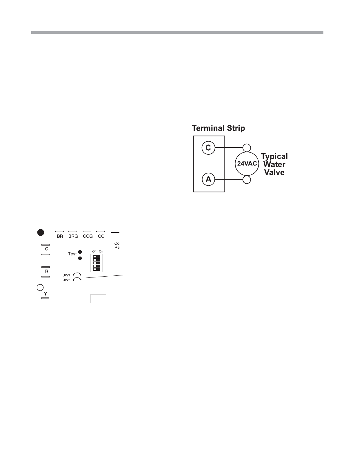
Second stage heating (backup boiler): Optimal heat pump
sizing may not include a water-to-water heat pump that can
handle 100% of the heating load. When a backup boiler is
used to supplement the heating capacity, a 24VAC output
from the THW unit can energize the boiler. The boiler control
box simply needs a relay that can be used to interface with
the THW unit.
DHW priority: By default, DHW heating always takes priority
over space heating. Normally, the hot water load will be
satisfied quickly, and the unit can then switch back to space
heating.
Time schedule: DHW temperatures may be adjusted
during occupied/unoccupied times via the user interface to
save energy costs.
Vacation mode: DHW generation may be disabled when the
user interface is placed in vacation mode. A return date and
time may be set to restore normal DHW temperatures.
Emergency DHW generation: If the THW unit is locked out, a
24VAC signal can be sent to a contactor at the water heater
to allow the operation of the electric elements and associated
thermostat.
Enhanced heat pump lockouts: Like any ClimateMaster
unit, the CXM board locks out the compressor any time a
lockout condition occurs. The MPC reads the lockouts from
the CXM, and reports the condition to the user interface.
The user interface changes from a blue backlight to a red
backlight, indicating a lockout. The actual lockout is reported
(e.g. High Pressure) at the interface. In addition to the
standard CXM faults, the MPC checks for bad thermistors
and high compressor discharge temperature, which are also
reported at the user interface.
Pump control: If the optional load and source pump(s) are
selected, the control energizes the pumps any time the
compressor is operating.
Variable speed floor pump (VSFP) output: Some radiant floor
systems utilize a variable speed pump on the floor system,
which changes flow based upon the number of zones open
or closed. Since the pump has built-in controls, only a power
supply is needed. An optional power terminal is available for
VSFP applications.

Electrical - Controls
PROGRAM
MENU
MODE
MAIN MENU
SET DATE
AND TIME
OPERATING
MODE
TEMPERATURE
OFFSETS
PROGRAM
SETTINGS
DAYLIGHT
SAVINGS
SET MONTH,
DAY, YR, HR, MIN
VACATION
HOLD DATE
THEN TIME
SECURITY
LOCKOUT
TEMP ADJUST
LOCKOUT
TOTAL KEYPAD
LOCKOUT
SCREEN
SETTINGS
PROGRAM
SCREEN
SERVICE
INFORMATION
FAULT
STATUS
TEMPERATURE
STATUS
CLEAR FAULT
HISTORY
EVENTS
PER DAY
2ND STAGE
HEAT
WM. WEATHER
SHUTDOWN
CONTRAST
BACKLIGHT
F OR C
12 OR 24 HOUR
CLOCK
LANGUAGE
MAIN SCREEN
FAULT
DESCRIPTION
Tranquility®High Temperature Water-to-Water (THW) Series
Rev.: 28 Aug., 2014
20 Geothermal Heating and Cooling
Figure 12: THW User Interface Menu
Other manuals for THW Series
1
This manual suits for next models
1
Table of contents
Popular Water System manuals by other brands

Watts Premier
Watts Premier 5 SV DELUXE Installation, operation and maintenance manual

Infiltrator
Infiltrator H-20 installation instructions

Real Spirit
Real Spirit AIR WATER LIFE Aqua Ionizer Deluxe owner's manual

Puro
Puro 35T Installation, operation & service manual

Culligan
Culligan Good Water Machine AC30 owner's guide

AL-KO
AL-KO HW 800/MC instruction manual

Miele professional
Miele professional UG 70-60/80 operating instructions

Kenmore
Kenmore 625.347031 manual

Everpure
Everpure ExuberaPRO Premium Carafe Water System brochure

Franklin Electric
Franklin Electric SubDrive300 installation manual

Bradley
Bradley S19-620 Installation

Gardena
Gardena 1874 operating instructions