ENERGY KINETICS EK-Pak Service manual

Owner and Installation
Manual
Natural Gas and Propane
Heat and Hot Water System
Energy Kinetics, Inc.
51 Molasses Hill Rd.
Lebanon, NJ 08833
www.energykinetics.com
First Edition - December, 2002 X:\TechDocs\Installation_Manuals\EK-Pak\EK-Pak Installation Manual 1st.doc
Note to the installer: Attach this manual in its bag on or near the EK-Pak heating system.
The manual must be in plain sight while viewing the system.
EK-Pak Owner and Installation Manual
EK-Pak Owner & Installation Manual First Edition December 2002 1
Please Read This First:
Special Attention Flags
Please pay particular attention to the following flags when you see them throughout this
manual.
DANGER: Notifies you of hazards that WILL cause severe personal injury, death or
substantial property damage.
WARNING: Notifies you of hazards that CAN cause severe personal injury, death or
substantial property damage.
CAUTION: Notifies you of hazards that WILL or CAN cause minor personal injury or property
damage.
NOTICE: Notifies you of special instructions on installation, operation, or maintenance that
are important, but not normally related to injury or property damage hazards.
WARNING: If the information in this manual is not followed exactly, a fire or explosion may
result, causing property damage, personal injury or loss of life.
WARNING: Do not store or use gasoline or other flammable vapors and liquids in the vicinity
of this or any other gas appliance.
Provide unobstructed combustion air openings sized and located per heating
module manual and applicable codes.
WHAT TO DO IF YOU SMELL GAS
•Do not try to light any appliance.
•Do not touch any electrical switch; do not use any phone in your
building.
•Immediately call your gas supplier from an outside phone.
•Follow the gas supplier’s instructions.
•If you cannot reach your gas supplier, call the fire department.
WARNING: Installation and service must be performed by a qualified installer, service
agency or the gas supplier.
Retain this manual for use by your qualified service technician only.
Should you observe unusual or abnormal operation of the burner or
heating module, contact your qualified service technician immediately. Do
not attempt to service or repair this product yourself.

EK-Pak Owner and Installation Manual
EK-Pak Owner & Installation Manual First Edition December 2002 2
WARNING:
Have the burner/heating module started up and serviced at least once
annually by a qualified service technician. Professional care is
necessary to properly service your equipment and verify it is operating
reliably. Failure to properly maintain the equipment could result in
severe personal injury, death or substantial property damage.
WARNING: You must keep the area around the burner/heating module free from the
following. Failure to comply could result in severe personal injury, death
or substantial property damage due to potential fire, explosion or
equipment damage from corrosive flue products.
•Do not store or use gasoline or other flammable vapors or liquids
near or in the same room as the burner.
•Do not use or store laundry products, paint, varnish, thinner or
other such chemicals near or in the same room as the burner/
water heater. These chemicals cause creation of acids in the
burner, heat exchanger and vent system that can cause severe
damage.
•Do not store combustible materials near or in the same room as
the burner/heating module.
General care and maintenance
Please read through the information provided for you in this manual. Ask your
qualified service technician to explain normal operation of your equipment.
Daily inspect the space around the burner/heating module to verify the area is
clean and free of the materials listed above.
Periodically watch the operation of your burner/heating module through an
operating cycle to verify normal operation. If you notice unusual conditions or
equipment behavior, contact your qualified service technician. Follow the
instructions on the next page to shut down the burner/heating module while
waiting for the technician.
EK-Pak Owner and Installation Manual
EK-Pak Owner & Installation Manual First Edition December 2002 3
FOR YOUR SAFETY READ BEFORE OPERATING
A. This burner does not have a pilot. It
is equipped with an ignition device
which automatically lights the
burner. Do not try to light the burner
by hand.
C. Use only your hand to turn the installer
supplied Manual Gas Shut Off Valve. If
the valve will not turn by hand, don’t try to
repair it, call a qualified service technician.
Force or attempted repair may result in a
fire or explosion.
B. Before OPERATING, smell all
around the heating module area for
gas. Be sure to smell next to the
floor because some gas is heavier
than air and will settle on the floor.
See below.
D. Do not use this heating module if any part
has been under water. Immediately call a
qualified service technician to inspect the
heating module and to replace any part of
the control system and any gas control,
which has been under water.
WHAT TO DO IF YOU SMELL GAS
•Do not try to light any appliance.
•Do not touch any electric switch; do not use any phone in your building
•Immediately call your gas supplier from a neighbor’s phone. Follow the gas
supplier’s instructions.
•If you cannot reach your gas supplier, call the fire department.
OPERATING INSTRUCTIONS
1. STOP! Read the safety information above.
2. Set the thermostat(s) to their lowest setting.
3. Turn off all electrical power to the burner/heating module.
4. This burner is equipped with an ignition device which automatically lights the
burner.
5. Do not try to light the burner by hand.
6. Actuate installer supplied Manual Gas Shut Off Valve located outside the unit to
the OFF position.
7. Wait five (5) minutes to clear out any gas. Then smell for gas, including near the
floor. If you smell gas, STOP! Follow the safety information above. If you don’t
smell gas, go to the next step.
8. Actuate installer supplied Manual Gas Shut Off Valve located outside of the unit to
the ON position.
9. Set thermostat(s) to desired setting.
10. Turn on all electric power to the burner and heating module.
11. If the burner/heating module will not operate, follow the instructions “TO TURN
OFF GAS TO THE BURNER” below and call your service technician or gas
supplier.
TO TURN OFF GAS TO THE BURNER
1. Set thermostat(s) to their lowest setting.
2. Turn off all electric power to the burner and heating module if service is to be
performed.
3. Actuate the installer supplied Manual Gas Shut Off Valve to the OFF position. Do
not force.
WARNING: If you do not follow these instructions exactly, a fire or explosion
ma
y
result causin
g
p
ro
p
ert
y
dama
g
e,
p
ersonal in
j
ur
y
or loss of life.

EK-Pak Owner and Installation Manual
EK-Pak Owner & Installation Manual First Edition December 2002 4
Record of Installation
Installer Name:
Installer Address:
Installer City, State:
Date Installed:
Notes:
All installations must be made in accordance with all State and Local Codes, which may
differ from this manual and in accordance with the following Codes, as applicable:
National Fuel Gas Code, ANSI Z223.1/NFPA 54:
Installation Codes, CAN/CGA B149
National Electrical Code, ANSI/NFPA 70
Canadian Electrical Code Part I, CSA 22.1, Electrical Code
Chimneys, Fireplaces, Vents and Solid Fuel Burning Appliances, ANSI/NFPA 211
Where required by the authority having jurisdiction, the installation must conform to the
Standard for:
ANSI/ASME CSD-1 Controls and Safety Devices for Automatically Fired Boilers
These codes are available from:
National Fire Protection Association
1 Batterymarch Park
Quincy, MA 02269-9101.
EK-Pak Owner and Installation Manual
EK-Pak Owner & Installation Manual First Edition December 2002 5
TABLE OF CONTENTS
Page Topic Page Topic
1 Please Read This First 18 Plate Heat Exchanger
4 Record of Installation 19 Flush, Purge, and Fill System with Water
5 Table of Contents 19 Heating module Water Treatment
6 Overview 19 Anti Freeze
6 Features 19 Winterizing
7 EK-Pak Technical Specifications 20-21 Combustion Air and Venting
7 Versatile Heating Output 22 Prepare for Start Up
7 Theory of Operation 22 Start Up Procedure
8 Typical Control Sequence 23 Start Up
9 Quick Setup Guide 24 Annual Maintenance
9 Receiving and Unpacking 24-25 Trouble Shooting
10 Components Diagram 26 EK-Pak Hot Water Knockdown
11 Hot Water Piping Schematic 27 Gas Protection Kit
12 Location and Clearances 28 Example Baseboard Sizing
12 General Assembly 29 Example Air Handler Sizing
12 EK-Pak Mounting 30 Example Piping Diagram for Baseboard,
Domestic and Radiant.
13 Wiring 30 Example Wiring Diagram for Baseboard,
Domestic and Radiant
13 Typical Wiring Diagram 31 Example Piping Diagram for Multiple EK-
Paks and Injection Loop.
14 Gas Piping Systems 32 Example Wiring Diagram for Air Handler with
Electronic Fan Center
16 Gas Pipe Leak Testing 33 Example Wiring Diagram for Air Handler with
Mechanical Relay Fan Center
17 Gas Flow Pressure Drop 34 Category III Venting (Z-Vent)
18 Zone Control 35 Replacement Parts
18 Hot Water Storage Tank
Inside
Back
Cover
Limited Lifetime Warranty Back
Cover Warranty Transfer Agreement

EK-Pak Owner and Installation Manual
EK-Pak Owner & Installation Manual First Edition December 2002 6
Overview:
Small Package – Large Performance
About the size of a large suitcase, the compact EK-Pak is one-fifth the size of systems with
comparable capacity. On the wall or in a closet, the EK-Pak fits the smallest home to the
largest commercial building.
Dependable, Reliable, Easy to Install
Using a time-proven design, the EK-Pak delivers futuristic performance with superior reliability.
EK-Pak’s stainless steel burners, long lasting copper and brass waterways, and non-
condensing design deliver low maintenance peace-of-mind. Designed with installation and
service in mind, the EK-Pak system comes pre-piped and pre-wired.
Saves Money
No pilot light! No chimney! No big bills! The EK-Pak uses sophisticated Variable Input
Technology to deliver heat only when it’s needed, and saves energy by not maintaining
temperature. EK-Pak can save more than 45% on utility bills.
Clean, Safe & Environmentally Friendly
Engineered with total efficiency in mind, the EK-Pak uses sealed combustion and “smart”
safety monitoring devices to ensure that the system is working flawlessly and as clean as
possible. EK-Pak meets the stringent SCAQMD (Southern California Air Quality Management
District) approval for lowest possible emissions.
Features:
♦Well equipped trim package for high performance space heating and hot water applications
includes:
ocirculator, multi-zone control with LED indicators,
oheating module feed,
oback-flow preventer,
oair elimination,
ooversized strainer with back flush and purge valves, and piping
oconveniently pre-piped and pre-wired wall mountable package.
♦Closed loop system allows for optional anti-freeze or boiler water treatment.
♦Oversize #60 mesh water strainer in closed loop circuit.
♦Temperature settings of 105F, 112F, 120F and 180F
♦Zone control with hot water priority.
♦Non-condensing design means no corrosive condensate
♦Domestic hot water storage tanks available in 40, 80 and 120 gallon sizes.
♦EK-Paks for LP/Propane include Gas Protection Kit for gas leak & carbon monoxide
detection.

EK-Pak Owner and Installation Manual
EK-Pak Owner & Installation Manual First Edition December 2002 7
EK-Pak Technical Specifications
Natural Gas or Propane
Dimensions 28”H x 32”W x 10” Deep
Net Weight 110 lb. Package (60 lb. Heating Unit)
Input Rate BTU/hr Min 20,000 – Max 185,000
Natural Gas Min 19,000 – Max 175,000
LP/Propane
Electric supply 120 Volts, 60 Hz, 1.8 Amps max.
Energy Factor 84% Natural Gas 85% LP (Propane)
Closed Water Loop Recirculated heating system water for maximum reliability
Sealed Combustion 4” flue
3” PVC or flex combustion air intake
Venting Category III Positive Pressure, (Z-Vent)
Versatile Heating Output
Baseboard Heat 60,000 BTU/hr output (with 20% oversized radiation)
Hydro-Air Heat 120,000 BTU/hr output
Domestic Hot Water 164 GPH (80,000 BTU/hr output at 140F outlet water
temperature)
Radiant Heat &
Hot Tub 150,000 BTU/hr (105F Maximum radiant temperature)
80,000 BTU/hr (140F Maximum radiant temperature)
Pool Heating 150,000 BTU/hr output
Heat Pump Backup 120,000 BTU/hr output
Snow-Melt 150,000 BTU/hr output
Theory of Operation
A very reliable, gas fired, modulating wall hung heating module is the source of heat for the
system. A fully featured closed loop hydronic heating system is integrated into the system.
The extremely versatile design is based upon research, development and field testing with
homeowners, professional installers and service people.
The EK-Pak system has been designed with a high head circulator to obtain maximum
water flow rate through the water heater. The advanced design uses a high pressure drop
through the heating module heat exchanger to achieve it’s efficiency and extraordinary speed
of response. Unlike conventional boilers, the high head circulator pumps into the heating
module heat exchanger, rather than pumping away from the heating module heat exchanger.
Due to the high pressure drop through the heat exchanger, the rest of the system, such as
baseboard, will remain at a reasonably low pressure.
A thermostat calls for heat and the zone control unit opens the appropriate zone valve and
starts the circulator. The heating module includes a flow switch that turns on the heating circuit
whenever flow through the heating module is detected. Once water begins to flow through the
zone, the heating module will turn on and begin to heat up the water flow to achieve the
desired supply temperature. Typically the supply temperature increases very quickly, so
quickly that a hand held on the supply pipe will have to be removed in about fifteen seconds.
Once the call for heat is satisfied, the zone control will close the zone valve and stop the
circulator.

EK-Pak Owner and Installation Manual
EK-Pak Owner & Installation Manual First Edition December 2002 8
Typical Control Sequence
♦Thermostat calls for heat and the zone control unit turns on the LED for that zone.
♦Zone control unit opens the zone valve and turns on the circulator.
♦Heating module fires and heats the water supply temperature to set point.
♦Heating module will control firing rate automatically to maintain supply temperature.
♦Thermostat is satisfied.
♦Zone control unit closes zone valve and turns off circulator.
♦Heating module turns off and waits for the next heat call.
The EK-Pak heating module is fully modulating and will do everything it can to maintain a
constant supply temperature. The return temperature will vary depending on how much heat is
taken away at the heat load. The module will vary the amount of gas being burned and can
even restrict the flow of water through the exchanger in order to maintain a constant supply
temperature.
The following charts illustrate the modulation effects. Remember that the return
temperature will vary according to the heat load and the supply temperature will always be
held constant. This example has the option switches set to maintain 180°F supply.
For example, let’s say we have a baseboard zone being supplied hot water at 180F and the
zone is sized to take away enough heat for the return water to be cooled down to 150F. Look
at the firing rate versus return temperature chart and you will see that at a return temperature
of 150F, the firing rate will be about 60,000 Btu/hour.
As a second example, let’s take a radiant zone for a large basement or for snow melting.
The zone is designed to be supplied with water at 95F. We will obtain 95F supply to the
radiant zone by mixing 180F heating module supply water with recirculated radiant return
water. The radiant return water is at 80F. Look at the firing rate chart and at 80F return water,
the firing rate will be 175,000 Btu/hour. Because the 80F return temperature is on the flat part
of the firing rate curve, the water heater will slow down the water flow through the water heater.
Look at the water flow chart and at 80F, the water flow through the water heater will be 3.5
gpm instead of the maximum flow of 4 gpm.
These two examples illustrate why the heat delivery ratings vary depending on the type of
heating load.

EK-Pak Owner and Installation Manual
EK-Pak Owner & Installation Manual First Edition December 2002 9
Quick Setup Guide
♦Unpack
♦Mount on wall
♦Install venting
oVerify venting is well sealed.
♦Install fresh air
oVerify fresh air piping is well sealed.
♦Pipe to gas supply
oTest gas piping for leaks
♦Pipe to water supply
♦Pipe to zones
oFill with water and check for leaks
♦Follow purge procedure to flush system of dirt, flux, and other debris, and to remove all
air from the system and zone piping.
♦Wire thermostats to zone control box
♦Wire zone valves to zone control box
♦Wire 120VAC to heater
♦With gas shut off, test system operation. Apply a call for heat, zone control will open
zone valve and start circulator. The heater will lock out and flash the ‘no gas’ code.
♦Turn on gas and test system operation.
Receiving and Unpacking:
Inspect shipment upon receipt for external damage. When unpacking and uncrating,
inspect each item for internal damage. Any damage found should immediately be reported to
the freight carrier before installation. The receiver is responsible for following the claims
procedure of the freight carrier. The freight carrier is responsible for taking prompt action on all
claims. If freight cannot be inspected at the time of delivery, sign the bill of lading “Subject to
Inspection” and inspect the shipment as soon as possible after receipt. Replacements for parts
damaged in shipment are available upon receipt of a signed copy of a claim report (concealed
damage claims should be filed immediately against the freight carrier by the consignee).
After unpacking, check each item against the packing list. Inspect it thoroughly for loose
parts, instruction sheets and packing lists. Immediately report any missing items. It is wise to
complete the installation before discarding packing material. Store all parts where they will not
be damaged or lost during installation.
EK-Pak Owner and Installation Manual
EK-Pak Owner & Installation Manual First Edition December 2002 10
Components Diagram
EK
K
p
a
To EK-Pak
Connection
Feedwater
Install properly sized
diaphragm expansion
tank. (Not Included)
Purge Ball Valve
30 PSI Relief Valve
#14 Plate Heat Exchanger
(Heat & Hot Water
System Only)
One Zone Valve
(Heat & Hot Water
System Only)
4 Zone Control Box with
Hot Water Priority Switch
(Switch must be turned on
for Domestic or Heat
& Hot Water Systems) Supply
Automatic
Air Vents
EK-Pak
Natural Gas
or Propane
4" Vent
3" Combustion
Air Intake
#60 Mesh Strainer
High Head Circulator
Automatic Boiler Feed
Zone Valves
(Not Included)
Domestic Out
To Tank
"C" Port

EK-Pak Owner and Installation Manual
EK-Pak Owner & Installation Manual First Edition December 2002 11
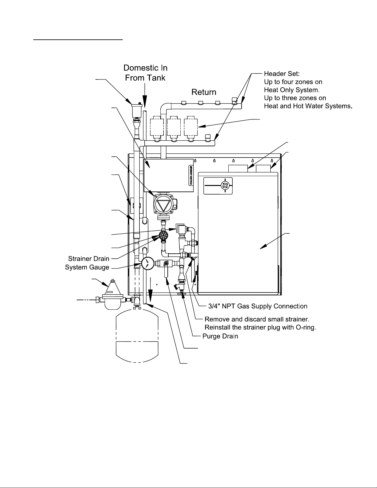
Hot Water Piping Schematic:
(Actual piping will vary per application)
To Tank
Connection
Feedwater
Drain
Backflush
Smart Pump
Check
Spring
Glass-Lined
Tank
Hot Water
Standard
Hot Water
To House
42 Gal.
Tank Drain
Plate Heat
Exchanger and
Zone Valve shown
in phantom are
pre-piped on Heat
& Hot Water
Systems

EK-Pak Owner and Installation Manual
EK-Pak Owner & Installation Manual First Edition December 2002 12
Location and Clearance:
DANGER:Provide clearance to combustible surfaces in accordance with all local and national
codes. Follow National Fire Protection Association Bulletin NFPA Installation of Oil Burning
Equipment and all applicable codes.
Installation Clearances from EK-Pak
Surfaces Clearance to Combustibles Suggested Clearance
for Service
Front 4” 24”
Back 0 0”
Left Side 0 12”
Right Side 0 1”
Top 8” 12”
Bottom 0 12”
General Assembly
Warning: Installation or service of this heating module requires a licensed person or
qualified professional service technician. Operation creates carbon monoxide gas and flue
gases which can cause serious injury or death. Improper installation, improper operation, or
installation by an unqualified person will void warranty.
1. Read this manual before beginning the installation.
2. The gas regulator inside the heating module is preset at the factory and is computer
controlled. No adjustment should be needed.
3. Well water or hard water may cause scale problems if not treated.
4. Maintain proper space for servicing. Install the unit so it can be connected and serviced
easily.
5. Avoid installing in areas with high levels of dust, sand or debris. Particles may obstruct
the air vent, reduce fan function or cause improper combustion.
6. Assembly of various packaged units is illustrated throughout this manual. The use of
non-Energy Kinetics supplied pump, controls and accessories should follow good
practices. The diagrams and locations presented in the manual are recommended.
7. Do not install the unit so that the exhaust vent is directed into any opening in a building
or where the noise may disturb neighbors.
EK-Pak Mounting:
Wall Mounting: The rear panel of the EK-Pak enclosure has keyholes punched across the
top on four inch centers. Two screws may be started into the wall and the unit hung on to
them. Add at least one more screw to the top and at least two more in the row of mounting
holes provided at the bottom. Locate the unit as desired following all applicable local codes
and clearances.
Pipe So There Is No Interference With the Cover: To avoid conflicts with the front cover,
piping to and from the system should be run from the top or the bottom. Any piping from the
side of the unit may prevent the cover from being installed.
EK-Pak Owner and Installation Manual
EK-Pak Owner & Installation Manual First Edition December 2002 13
Wiring:
Electrical connection
•The EK-Pak heating module requires 120VAC, 60 Hz, less than 12 amps.
•Connect 120VAC from a switched circuit so the heating module is constantly powered.
•The EK-Pak heating module has a built-in Ground Fault Interrupter, GFI.
•Remove cover and test the GFI by pressing ‘test’, press ‘reset’ to restore power.
•It should be grounded in accordance with the most recent edition of the National
Electrical Code, ANSI/NFPA 70 and any local codes.
•Do not rely on the gas or water piping to ground the metal parts of the heating module.
•A service switch or a fused disconnect must be mounted in accordance with local
codes.
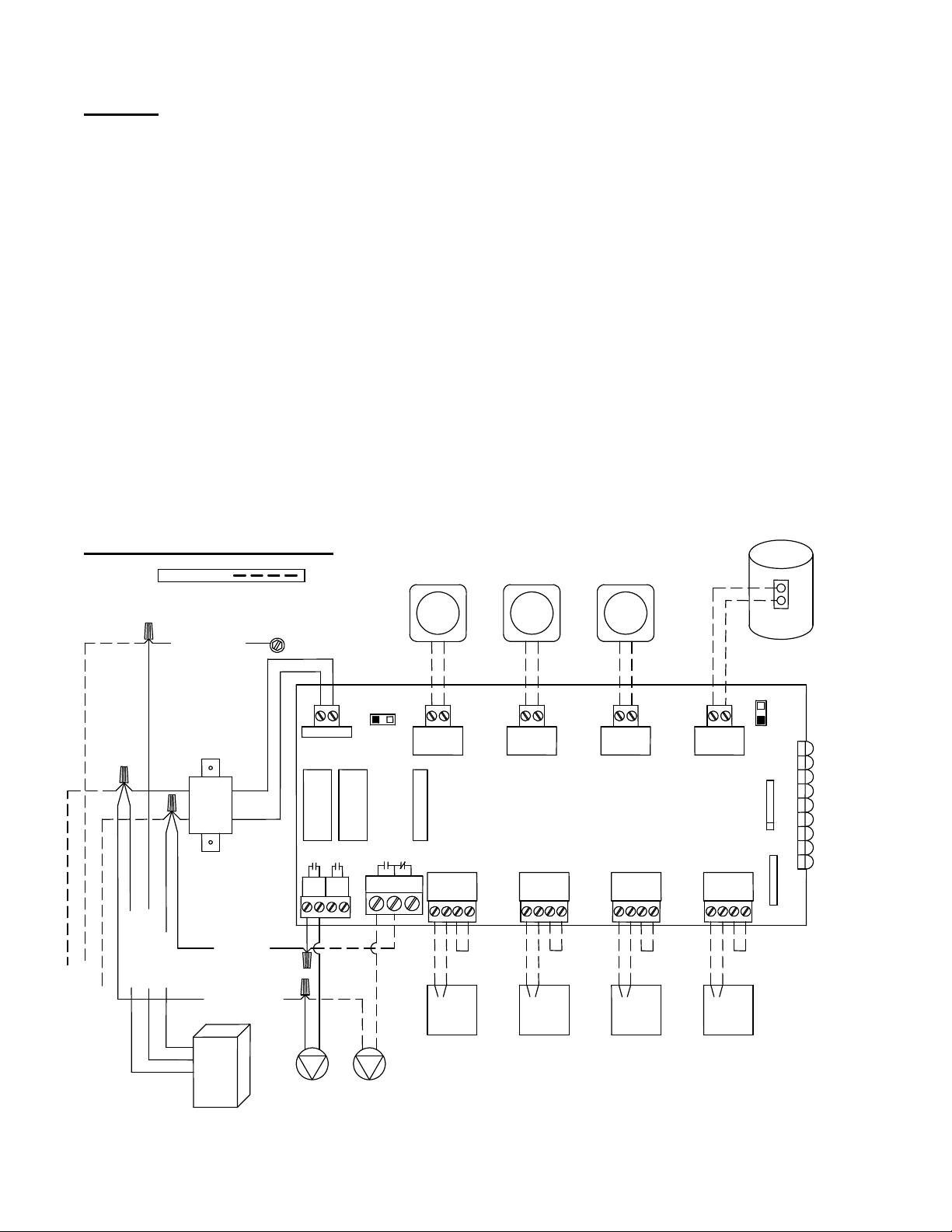
•Wire the zone control as shown. For non-end switch zone valves, add jumpers across
terminals # 3 & 4 as shown on zone output terminal blocks.
•For Erie zone valve, set thermostat heat anticipator to 0.35 amperes.
CAUTION: Label all wires prior to disconnection when servicing controls. Wiring error can
cause improper and dangerous operation. Verify proper operation after servicing.
Typical Wiring Diagram:
ZONE 1
T T T T
ZONE 2 T T
ZONE 3 T T
ZONE 4
1 2 3 4
ZONE 1 1 2 3 4
ZONE 2 ZONE 3
1 2 3 4 ZONE 4
1 2 3 4
Thermostat
POWER IN
MODE
NORMAL RESET
ZONE 4 PRIORITY
OFF
ON
FUSE (3amp MAX)
EK-Pak Zone Control
24
VAC
MAIN
END
SWITCH EXTRA
END
SWITCH N/O COM N/C
ZONE 4 RELAY
MOTOR
Zone Valve
(Power Open,
Self Closing)
MOTOR MOTOR MOTOR
JUMPER
Hot Water
Storage Tank
A
quastat
T STAT 1
VALVE 1
T STAT 2
VALVE 2
T STAT 3
VALVE 3
T STAT 4
VALVE 4
POWER
FIELD WIRING:
White (Neutral)
Green (Ground)
Black (Hot)
120 VAC
INPUT
Factory
Installed
Transformer
EK-Pak
White (Neutral)
Green (Ground)
Black (Hot)
GROUND
SCREW
SYSTEM
CIRC DHW
CIRC
Green (Ground)
Black (Hot)
White (Neutral)
Thermostat Thermostat
Zone Valve
(Power Open,
Self Closing)
Zone Valve
(Power Open,
Self Closing)
Zone Valve
(Power Open,
Self Closing)
JUMPER
JUMPER JUMPER

EK-Pak Owner and Installation Manual
EK-Pak Owner & Installation Manual First Edition December 2002 14
GAS PIPING SYSTEMS
Attention: Proper gas pressure is important but gas volume is more critical than pressure.
Maximum performance can be expected only if the right gas volume is supplied. Calculate the
supply piping size for the right gas volume.
Attention: Check the rating plate on the EK-Pak heating module to verify that it is for the
correct type of gas. The heating module cannot be converted from natural gas to propane or
from propane to natural gas in the field. Contact your local Energy Kinetics Dealer to obtain
the correct unit for your gas type.
WARNING: Pressure testing of the gas supply piping system must be done properly.
When pressure testing the gas supply piping system at test pressures in excess of 1/2 psi
(3.5 kPa, 14 in w.c.), the heating module and its individual manual shutoff valve must be
disconnected from the gas supply piping system.
When pressure testing the gas piping system at test pressures equal to or less than 1/2 psi
(3.5 kPa, 14 in w.c.), the heating module must be isolated from the gas supply piping system
by closing its individual manual shutoff valve.
Gas piping must be properly sized in accordance with the National Fuel Gas Code, NFPA
54, or according to state and local codes as applicable. Gas piping must be sized to provide
the maximum firing rate gas flow for all appliances in the building.
Do not use any bushings or service 90 degree elbows. Use only full port shutoff valves. If
in doubt, oversize the piping. For Natural Gas installations, be sure to verify that the gas meter
is properly sized for all appliances.
The following tables show suggested sizing for Black Iron Pipe. Be sure to add the
appropriate equivalent length for every fitting and elbow used.
For other types of pipe or tubing, consult NFPA 54 or the manufacturer of the pipe or tubing
or your gas supplier for pipe sizing information.
For Propane Gas, drawing up to 175,000 Btu/Hr ( 75 Cubic Feet per Hour).
For Natural Gas, drawing up to 185,000 Btu/Hr (185 Cubic Feet per Hour).
Natural Gas Propane Gas
Iron Pipe Size Maximum Equivalent
Length Iron Pipe Size Maximum Equivalent
Length
3/4 inches 20 feet 3/4 inches 40 feet
1 inch 60 feet 1 inch 125 feet
1-1/4 inches 200 feet 1-1/4 inches 200 feet
Gas supply pressures must be within the ranges on the following chart:
Natural Gas
Supply Pressure Min. 5” WC
Max. 10.5” WC
Propane Gas
Supply Pressure Min. 11” WC
Max. 14” WC
EK-Pak Owner and Installation Manual
EK-Pak Owner & Installation Manual First Edition December 2002 15
WARNING: Fire or explosion may result if the maximum supply pressures are exceeded.
Always purge the gas line of any debris before connecting to the heating module.
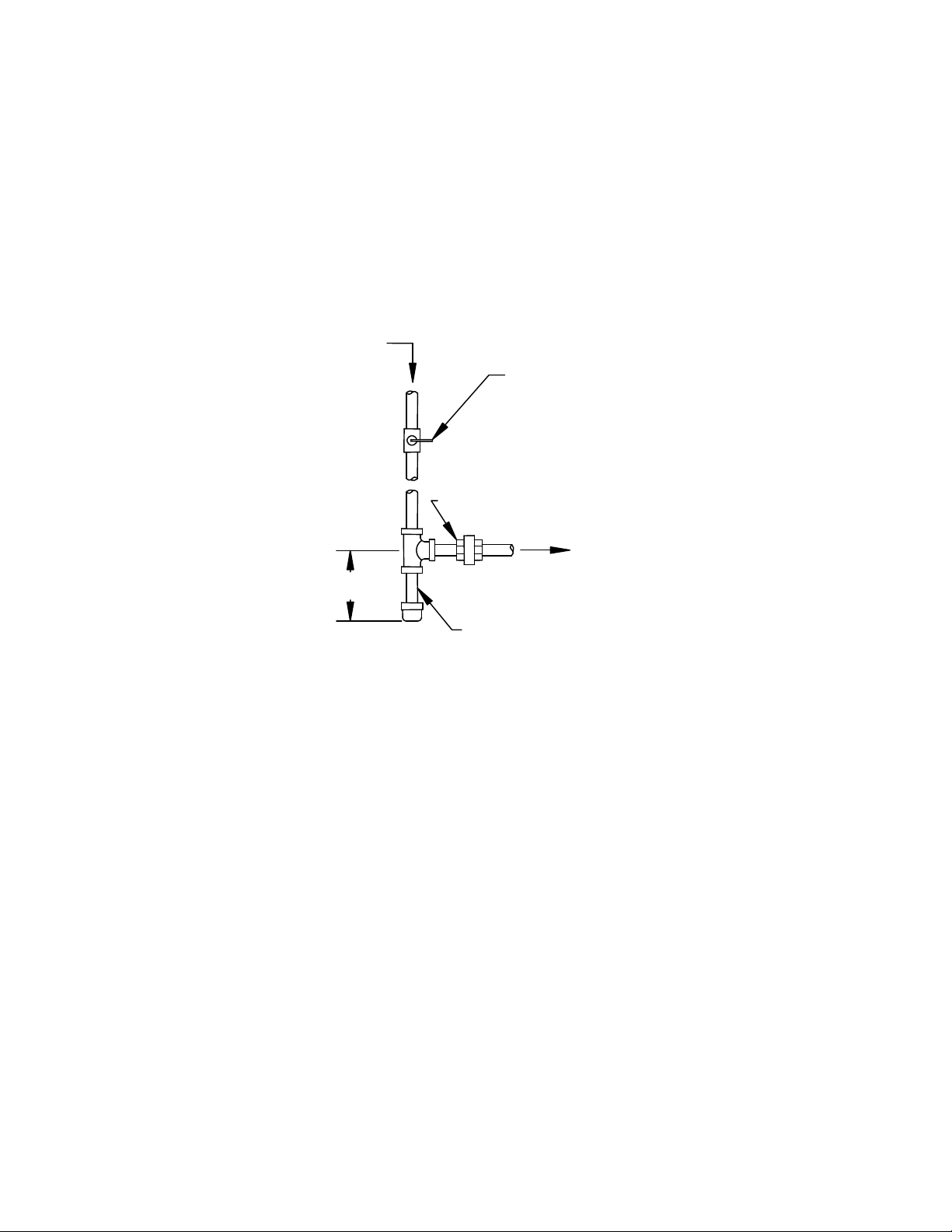
A manual shut off valve and a sediment trap must be provided by the installer in the gas
piping upstream of the heating module. The sediment trap should be located as close to the
inlet of the unit as possible at the time of installation. The heating module and its gas
connection must be tested for gas leakage before placing the heating module in operation.
Check for leaks by using a gas detector or applying a leak detection solution to all gas fittings
and connections.
Full Port Manual Shutoff Valve
Height of Shutoff Valve above ground
level to conform to any local codes.
Union
Sediment Trap/Drip Leg
3" Min
To check for gas leaks, use a
gas detector or apply a leak
detection solution to the joints.
Direction of flow

EK-Pak Owner and Installation Manual
EK-Pak Owner & Installation Manual First Edition December 2002 16
Gas Pipe Leak Testing:
All new or changed piping must be leak tested. Consult your gas supplier for more details on
leak testing.
•Install a manometer at the inlet side of the gas valve.
•With all appliances connected, and pilot lights shut off, apply normal regulated gas
pressure to the piping system.
•Record the starting manometer reading and the time of day.
•Close off the main gas shutoff valve outside the building.
•Wait at least three minutes after shutting the main gas valve.
•Record the ending manometer reading and time of day.
•The manometer reading should not have changed.
oExample:
start reading is 11-1/4” wc
end reading is 11-1/4” wc
there is not a leak.
•If the manometer reading drops, then there is a leak in the piping.
oExample:
start reading is 7.25” wc
end reading is 7.1” wc
there is a leak.
oIf you can detect any decrease in the reading of your gauge, there is a leak.
•Apply leak detection solution (as appropriate for your piping) to the piping to find the
leak.
•Fix the leak and repeat the above leak testing procedure.
Start Time Start Manometer
Reading End Time End Manometer
Reading
Z4
Z1

EK-Pak Owner and Installation Manual
EK-Pak Owner & Installation Manual First Edition December 2002 17
Gas Flow Pressure Drop and Regulator Lock Up Check:
This test is very important and will tell you whether your piping system is properly sized for the
maximum firing rate and whether your regulator is working properly.
•Record and total up the firing rates of all appliances in the building.
•Install a manometer at the inlet side of the gas valve.
•Turn on enough appliances to draw 50% of the maximum firing rate for the entire
building.
•The manometer pressure reading should be about 11” for Propane and about 7” for
Natural Gas.
•Turn on all appliances to draw 100% of the maximum firing rate for the entire building.
•The manometer pressure reading should not drop more than 20% below the 50% draw
flow pressure
oShould not decrease more than about 2” for Propane or 1.5” for Natural Gas.
If decrease is too much, then the piping/fittings/valves are undersized.
•Turn off all appliances, and shut off all pilot lights.
•The manometer pressure reading should not increase more than 20% over the 50%
draw pressure
oShould not increase more than about 2” for Propane or 1.5” for Natural Gas.
If increase is too much, then possibly the regulator is not working properly.
Record firing rate Record Manometer Reading
Running at 50% Firing Rate
Running at 100% Firing Rate
All gas flow stopped
Stopped
Example:
•There are four gas-fired appliances in the building. A water heater rated at 35,000
Btu/hr, a gas fireplace rated at 25,000 Btu/hr, a gas range rated at 65,000 Btu/hr, and
an EK-Pak heating module fired at 185,000 Btu/hr. The water heater, the fireplace, and
the range add up to 125,000 Btu/hr. Adding the firing rate for the EK-Pak heating
module gives a total of 310,000 Btu/hr.
•Turn on just the EK-Pak to get 185,000/310,000 = 60%.
•While running on natural gas, the EK-Pak gas valve inlet pressure is reading 6.5” w.c.
•Turn on the other three appliances and the EK-Pak gas valve inlet pressure drops to
5.0” w.c., which is just within the limit.
•Turn off all the appliances by closing their manual shutoff valves.
•The EK-Pak gas valve inlet pressure increases to 8” w.c., which is just within the limit.
From this test, we can say the piping is properly sized and the main gas regulator is working
properly
Z4
Z1

EK-Pak Owner and Installation Manual
EK-Pak Owner & Installation Manual First Edition December 2002 18
Zone Control:
ZONE CONTROL BY VALVE: The EK-Pak is designed to provide from one to four zones for
the heating system and domestic hot water. Energy Kinetics recommends and can supply two
wire, full port, 24-volt zone valves for control of each heating zone. Four wire zone valves with
end switches can also be used. Energy Kinetics recommends using four wire zone valves with
end switches for control of air handler zones. Refer to air handler wiring diagrams for details.
EXPANSION TANK SIZING: The type and size of expansion tank depends on the total
system water volume. NOTICE: Sizing must consider cold start and hot operation.
Hot Water Storage Tank:
The hot water piping schematic indicates a typical arrangement of the domestic hot water
system. The tank may be located adjacent to or in any other convenient location. If greater
than 10 feet away, use ¾” lines and a manual air vent on a high return. Insulation of water
lines between the storage tank and EK-Pak and on the hot water supply to the house is
recommended for best fuel efficiency. Energy Kinetics supplied storage tanks come complete
with high-density foam insulation, a properly located aquastat, a temperature/pressure relief
valve, and a specially designed dip tube.
DANGER:
Hot water temperature over 125F can cause severe burns instantly or
death by scalding. Children, disabled, and elderly are at the highest risk of
being scalded. Test water temperature before bathing or showering.
Temperature limiting, anti-scald mixing valves are available and recommended.
Hot water storage tank aquastat does not limit the maximum delivered
water temperature. The plate heat exchanger will always provide water that is
hotter than 125F into the hot water storage tank where it will mix with the water
in the storage tank. The hot water storage tank can deliver water hotter than
125F depending on the degree of tank temperature stratification. If codes place
limits on maximum delivered water temperature, an anti-scald mixing valve
MUST be installed on hot water tank outlet.
Plate Heat Exchanger:
NOTICE: The plate heat exchanger is piped at the factory and its location and orientation
should not be altered without consulting with Energy Kinetics.
Pipe domestic water to the connections as marked on the plate heat exchanger. When
ordering a replacement, order the part number shown in the Assembly Drawing.
WARNING:
The single wall plate heat exchanger complies with 1990 N.S.P.C. provided that both of the following
are true:
A) The heating module water (including additives) is practically non-toxic, having a toxicity
rating or class of 1 as listed in Clinical Toxicology of Commercial Products, 5th Edition; and
B) The pressure of the heating module water is limited to a max of 30 psig by an approved
safety or relief valve.

EK-Pak Owner and Installation Manual
EK-Pak Owner & Installation Manual First Edition December 2002 19
Flush, Purge, and Fill System with Water:
Follow these steps to flush, purge, and fill the system. Do not allow system pressure to exceed 30 psi.
♦Flush dirt, debris, and solder flux from system through the strainer drain.
oTurn off power to the system.
oClose purge ball valve.
oConnect hose to strainer drain and open fully.
oManually open one zone valve.
oOpen heating module water feed. Water will begin to flow through open zone.
oOpen the next zone manually before closing the flushed zone valve.
oRepeat until all zones have been flushed and then close the strainer drain.
♦Purge air from system through the purge drain.
oMove drain hose to purge drain from the strainer drain.
oOpen purge drain and verify purge ball valve is closed.
oManually open one zone valve.
oOpen heating module water feed. Water will begin to flow through open zone.
oOpen the next zone manually before closing the purged zone valve.
oRepeat until all zones have been purged.
oClose the purge drain and open the purge ball valve.
♦Fill the system through the heating module feed.
oAdjust to normal cold system pressure, 10 to 12 psi on pressure gauge.
oAdd pressure if too low, relieve pressure if too high.
Once the system has been properly flushed and purged, the system will vent any released air
during operation. NOTICE: AIR VENT CAP MUST REMAIN OPEN.Vent cap should be removed and
kept in a safe location. NOTICE: DO NOT START BURNER UNTIL THE SYSTEM IS FULL OF
WATER.Before placing system in operation, carefully check for leaks throughout system. Tighten
pipe joints, circulator flanges; check gaskets, etc., as needed.
Heating module Water Treatment:
Addition of heating module water treatment is recommended to reduce lime buildup inside
the heating module. Energy Kinetics recommends addition of one quart of 8-Way Boiler
Treatment per 30 gallons system water. 8-Way Boiler Treatment is recommended to treat
water up to medium hardness. Call Energy Kinetics for more details about heating module
water treatment and about hard water conditions.
Anti-Freeze:
Only non-toxic antifreeze (such as Propylene Glycol) should be used if adding anti-freeze
to a system that produces domestic hot water. Hard water should not be used in combination
with generic antifreeze. Energy Kinetics supplies a quality inhibited Propylene Glycol anti-
freeze with orange dye and an antifoam agent. 8-Way Boiler Treatment can be added to
Energy Kinetics anti-freeze and is recommended in areas of medium water hardness.
NOTICE: Thoroughly clean system prior to adding antifreeze. TSP is recommended for
removing flux and other oil based compounds. Once system has been cleaned and flushed,
then add antifreeze to obtain approximately a 30% by volume mixture of antifreeze in water.
Call Energy Kinetics for assistance in calculating how much anti-freeze to add to system.
Winterizing
The EK-Pak heating module comes equipped with heaters to discourage the unit from
freezing. For these heaters to work, there must be electrical power to the unit. This freeze
prevention system will not work if the electrical power source has been disconnected.
Table of contents
Popular Water System manuals by other brands

ModvlvS
ModvlvS Kascata manual

POBEL
POBEL 710 instruction manual

Rinnai
Rinnai Enduro XL SP250B Operation & installation manual

Condair
Condair RO Series Installation and operation manual

Stuart Turner
Stuart Turner Mainsboost MB 100SV Installation, operation & maintenance instructions

3P Technik
3P Technik Rustico instruction sheet

Everpure
Everpure Cartridge QCP10-TSGAC Specification sheet

Viega
Viega PureFlow installation manual

AMES
AMES Air Gap 400 Series installation instructions

Imetec
Imetec TYPE H1701 Instructions for use

Heatrea Sadia
Heatrea Sadia SUPERCHILL 30B Fitting instructions and user guide

Kenmore
Kenmore 625.384450 owner's manual


