manuals.online logo
Brands
  1. Home
  2. •
  3. Brands
  4. •
  5. Climax
  6. •
  7. Media Converter
  8. •
  9. Climax CL-AB-RF-W User manual

Climax CL-AB-RF-W User manual

Input Voltage
18V-24V DC (24V DC is recommended)
Input Current
100mA
I/O Connecons
C-Bus
4 X screw terminals
Output
1 X 5A relay channel (screw terminal)
Input
1 X digital dry contact input (screw terminal)
1 X 4-wire wiegand input
Product
Specifica on
(CL-AB-RF-W)Wiegand Converter
C-Bus
I/O Connecons
Wiegand Connecons
1. VCC
2. GND
3. A (Data+)
4. B (Data-)
5. Contact input
6. Normal open contact
7. COM
8. VCC (12V DC)
9. GND
10. Data 1 (Wiegand)
11. Data 0 (Wiegand)
No
C
In
B
A
-
+3
4
2
1
6
5
7
Power In: 18-24V DC
100mA max
CL-AB-RF-W
Wi egan d Conv erte r
-
+
D0
D1
8
9
10
11
1. Power LED
2. Status LED
3. Output LED
4. Input LED
5. Address selector switch
0 0 0 2 9 5 0 0 0 0 F A 1 4 E 7
Out
In
12 3 45
ON
5
1
2
3
4
INSTALLATION GUIDE version 1.0.1
3
4
1
2
Before wiring the device, always unplug the main power.
In case of using capaciv e or inducv e loads, permissible current is less than normal mode (resisv e load)
depending on load condion.
Use the following wiring diagram when input voltage of the Wiegand Reader is equal to 12V DC and
input current is lower than or equal to 100mA.
No
C
In
B
A
-
+
To Next Module
From Previous
Module
Power In: 18-24V DC
100mA max
CL-AB-RF-W
Wie gan d C on v er t er
-
+
D0
D1
MODE
Circut
Breaker
MODE
Circut
Breaker
MODE
Circut
Breaker
MODE
Circut
Breaker
MODE
Circut
Breaker
MODE
Circut
Breaker
MODE
Circut
Breaker
MODE
Circut
Breaker
N
L
Magnec
Door Lock
12V / 100mA
GND
In
No
C
In
B
A
-
+
To Next Module
From Previous
Module
Power In: 18-24V DC
100mA max
CL-AB-RF-W
Wie gan d C on v er t er
-
+
D0
D1
MODE
Circut
Breaker
MODE
Circut
Breaker
MODE
Circut
Breaker
MODE
Circut
Breaker
MODE
Circut
Breaker
MODE
Circut
Breaker
MODE
Circut
Breaker
MODE
Circut
Breaker
N
L
Magnec
Door Lock
External
Power Supply
-
+
GND
In
57
68
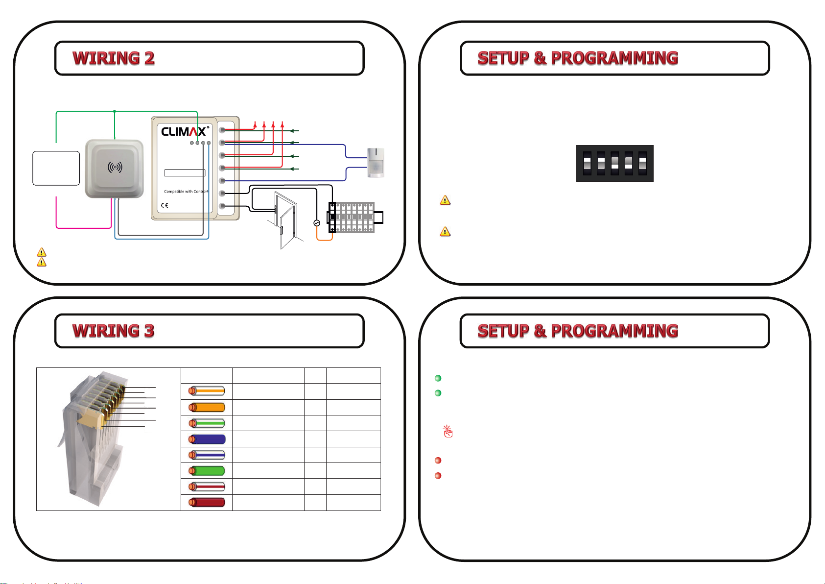
Change Module Address
The module address can be set from 0 to 31 by means of a dip switch called “address selector switch”.
Before changing module address the main power must be disconnected. The address must be defined
in binary. For instance to set address “19”, the dip switch must be as below:
Module’s LEDs
Power: When the module is connected to main power, “Power LED” will flash smoothly.
Status: When the module is connected to C-Bus network and receives valid data packets,
“Status LED” flashes quickly. “Status LED” is “off” when the module doesn’t receive any data.
When the module is receiving invalid data packet ,”Status LED” will remain “on” for 5 seconds.
In some cases, when a new module is added to C-Bus network, “Status LED” might remain
“on” for 5 seconds. This situa on must not be considered as an error.
Output LED: Shows the status of module’s relay.
Input LED: Shows the status of module’s input.
ON
12 3 4 5
Never set the address “0” and “1” as “0” is not valid in C-Bus protocol and “1” is always dedicated
for RS-232 GatewayPro module.
Check all C-Bus module addresses to avoid repev e address allocaon.
Before wiring the device, always unplug the main power.
In case of using capaciv e or inducv e loads, permissible current is less than normal mode (resisv e load)
depending on load condion.
12
34
56
78
Color Color Name Pin C-Bus
Orange/White
Orange
Green/White
Blue
Blue/White
Green
Brown/White
Brown
1
2
3
4
5
6
7
8
A(DATA+)
B(DATA-)
TXD*
RXD*
GND
GND
VCC
VCC
Use following instrucon to connect the module to C-Bus network with Cat6 cable.
* TXD & RXD are generally applicable for modules which are working in direct mode. for this
product TXD & RXD will be used in C-Bus networks with long cables, for GND & VCC respecv ely in
order to lower voltage drop.
Follow the diagram below when input voltage of the Wiegand Reader is not equal to 12V DC or
input current is higher than 100mA.

Popular Media Converter manuals by other brands

Monacor IMG STAGE LINE LSP-102 manual

Monacor

Monacor IMG STAGE LINE LSP-102 manual

Avtron SMARTach III AV850 manual

Avtron

Avtron SMARTach III AV850 manual

Cypress CM-392 Operation manual

Cypress

Cypress CM-392 Operation manual

LSI L64005 Technical manual

LSI

LSI L64005 Technical manual

Drawmer M-Clock Plus DMS-5 owner's manual

Drawmer

Drawmer M-Clock Plus DMS-5 owner's manual

Mastervolt MAGIC 12/12-20 user manual

Mastervolt

Mastervolt MAGIC 12/12-20 user manual

tams elektronik FD-5 manual

tams elektronik

tams elektronik FD-5 manual

Yamaha DSR-70PRO Operation manual

Yamaha

Yamaha DSR-70PRO Operation manual

RGBlink Q4L user manual

RGBlink

RGBlink Q4L user manual

RDS P132 Quick installation guide

RDS

RDS P132 Quick installation guide

LEGRAND C2G 29503 user guide

LEGRAND

LEGRAND C2G 29503 user guide

jbc CHB-A manual

jbc

jbc CHB-A manual

Hall Research Technologies SC-HD-2B user manual

Hall Research Technologies

Hall Research Technologies SC-HD-2B user manual

DeLOCK 62438 user manual

DeLOCK

DeLOCK 62438 user manual

Kaysun CWC 15 Operation manual

Kaysun

Kaysun CWC 15 Operation manual

SIERRA VIDEO SYSTEMS ADC-142 owner's manual

SIERRA VIDEO SYSTEMS

SIERRA VIDEO SYSTEMS ADC-142 owner's manual

Atlona AT-HDR-M2C-QUAD installation guide

Atlona

Atlona AT-HDR-M2C-QUAD installation guide

Gotek 1M44-GU user manual

Gotek

Gotek 1M44-GU user manual

manuals.online logo
manuals.online logoBrands
  • About & Mission
  • Contact us
  • Privacy Policy
  • Terms and Conditions

Copyright 2025 Manuals.Online. All Rights Reserved.