Climax Vesta Series User manual

Aug 21st, 2019

Table of Contents
1. INTRODUCTION ................................................................................................................................................... 1
1.1. PARTS IDENTIFICATION...................................................................................................................................... 1
1.2. ACCESSORIES INCLUDED.................................................................................................................................. 2
2. INSTALLATION GUIDE........................................................................................................................................... 3
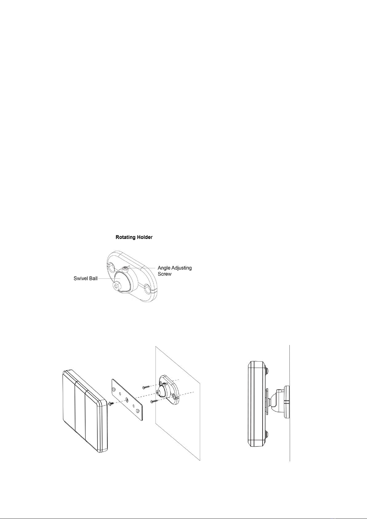
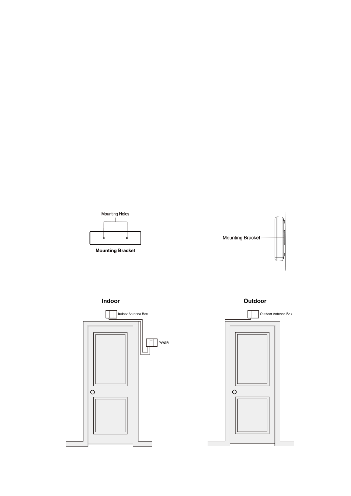
2.1 ANTENNA BOX INSTALLATION ................................................................................................................................ 3
2.2 PWSR INSTALLATION............................................................................................................................................. 4
2.3 SOFTWARE INSTALLATION ...................................................................................................................................... 5
3. SYSTEM CONFIGURATION .................................................................................................................................... 6
3.1. FINDER SOFTWARE ........................................................................................................................................... 6
3.2. SYSTEM ............................................................................................................................................................. 7
3.3. RF SNIFFER....................................................................................................................................................... 9
3.4. SR PROGRAM.................................................................................................................................................. 11
3.5. NETWORK........................................................................................................................................................ 12
3.6. I/O SETTING..................................................................................................................................................... 13
3.7. UPDATE &RESET............................................................................................................................................ 14

1
1.Introduction
The Patient Wandering System Receiver (PWSR), integrating Power over Ethernet into the
design, features wireless radio and input/output connections. Two antennas boxes are
connected to PWSR via telephone cords to capture RF signals in the air and report these
signals to the connected Server when users walk by the antennas. In addition, the built-in I/O
terminals can be further programmed to act on certain triggers.
1.1. Parts Identification
1 Power LED (Green)
ON: Power on
OFF: Power off
2 Indoor RF Sniffer LED (Red)
Flash: Reporting after RF signal reception
3 Outdoor RF Sniffer LED (Red)
Flash: Reporting after RF signal reception
4 I/O Trigger Indication LED (Blue)
ON: When an Input terminal is triggered, the Blue
indication LED will turn ON.
5 RF Port (Outdoor)
6 RF Port (Indoor)
7 Input & Output Terminal
Input: N.O. or N.C. connection
Output: DC 5V 30mA output
8 Ethernet Port
9 Factory Reset Button
10 Indoor or Outdoor Antenna Terminal

2
1.2. Accessories Included
A. 1x PWSR Mounting Bracket
B. 1x Ethernet Cable
C. 2x Telephone Cord (1.8M)
D. 2x Antenna Box Mounting Bracket
E. 2x Rotating Holder
F. 6x Wall Plugs for PWSR Mounting Bracket and Rotating Holders
G. 2x Flat Head Screws (3.5*22MM) for PWSR Mounting Bracket
H. 2x Machine Screws (4*8MM) for Antenna Box Mounting Brackets
I. 4x Tapping Screws (3.5*15MM) for Rotating Holders

3
2.Installation Guide
2.1 Antenna Box Installation
Step 1. Choose suitable locations above the door to install the Antenna Boxes. One
Antenna Box should be installed indoor, and the other Antenna Box should be
installed outdoor.
Step 2. Find the Rotating Holder provided (Picture1), and fix it to the wall with provided
screws.
Step 3. Fix the mounting plate on the swivel ball with the fixing screw secured through the
foolproof design hole, and then hook the Antenna Box onto the mounting bracket.
(Picture2)
Step 4. Rotate the swivel ball to adjust the Antenna Box’s orientation. It is recommended to
have the Antenna Box parallel to the wall for optimal performance. Lock the
position by firmly tightening the angle adjusting screw. (Picture3)
Picture1
Picture2
Picture3

4
2.2 PWSR Installation
Step 1. Choose a suitable location for the Receiver. Usually it is installed near the Indoor
Antenna Box. The Receiver also requires Ethernet with POE capability to operate.
Step 2. Find the PWSR Mounting Bracket provided, use the holes on the bracket to mark
mounting location on the wall. (Picture4)
Step 3. Drill holes into marked location and insert wall plugs if required, screw the bracket
onto the mounting location. Then Hook the PWSR onto the mounting bracket.
(Picture5)
Step 4. Use the provided telephone cords to connect the indoor Antenna Box and outdoor
Antenna Box to PWSR’s indoor RF port and outdoor RF port respectively.
(Picture6, 7)
Step 5. Plug in the Ethernet cable into Ethernet port to power up the Receiver.
Picture4
Picture5
Picture6
Picture7

5
2.3 Software Installation
The PWSR can be setup via LAN connection. Aspecial “Finder”software is provided for
identifying the Receiver on local network. Insert the installation CD into the CD-ROM drive,
locate the “Finder 1.x.exe”file, execute the file to install Finder software.

6
3.System Configuration
3.1. Finder Software
Use the Finder Software to connect to panel for programming.
Step 1. Execute the Finder software, it will search the local network and display PWSR
LAN IP automatically if the receiver is located. If no Receiver information is
displayed, check Receiver power and Ethernet and click “Search”to refresh search
result.
The Receiver’s network information can be programmed manually by selecting the
Receiver and clicking “Configure Setting”.
For name and password, enter admin / admin1234. Configure the network setting
and click OK to confirm when finished.
Step 2. Double click the Receiver info to open the browser and connect to Receiver

7
webpage. You will be required to enter a username and password.
Default Username: admin
Default Password: admin1234
Step 3. Upon entering correct username and password, you will enter the Receiver’s
Welcome webpage:
The Welcome Page displays
Firmware revision: The firmware version of the Control Panel
MAC address: The MAC address of your Control Panel
Click on the top column selections to enter different webpages for function selection.
3.2. System
Click on the “System”selection for Time zone and Date / Time settings, and configuration
backup.

8
Time zone:
A number of time zones are available to be selected. Press the “Change Timezone”
button to confirm time zone change.
Date & Time:
Adjust the Date and Time to the local time by clicking on the selection buttons. Press
the “Adjust Time”button to confirm Date and Time changes.
<
<N
NO
OT
TE
E>
>
The Date and Time will be synchronized to the local time after connecting to internet.
Configuration Backup:
Click on “Configuration Backup”to backup and restore your panel settings.
Click Backup configuration by saving as file to download current panel
configuration as a .bin file into your computer.
To apply a previously downloaded configuration setting to current panel, click
“Choose File”, select the .bin file in your computer and click “Restore”to apply
setting to panel.

9
3.3. RF Sniffer
RF Sniffer: RF Sniffer is designed for the Receiver to report to programmed destination
when it receives a signal from an RF device.
Sniffer Report Destination: Enter a report destination, 3 Report Indexes are available
for setting. If there are multiple Report Indexes programmed:
The PWSR will report according to the order (e.g. 1 > 2 > 3, etc.) of the Report
Indexes. Report will stop when one report is successful.
If all reporting failed at the first cycle, the PWSR will wait for 5 seconds to retry
reporting to all Report Indexes again. A total of 6 retries will be done (or until one of
the reports is successful). If all the retries fail, the PWSR will regard reporting
unsuccessful. From the example above, suppose all report failed, the report
sequence would be:
If 1 reporting destination is programmed:
1 > wait for 5 seconds > 1 > wait for 5 seconds > 1 > wait for 5 seconds >
1 > wait for 5 seconds > 1 > wait for 5 seconds > 1 > Stop reporting whether
succeeded or not
If 2 reporting destinations are programmed:
1 > 2 > wait for 5 seconds > 1 > 2 > wait for 5 seconds >
1 > 2 > Stop reporting whether succeeded or not
If 3 reporting destinations are programmed:
1 > 2 > 3 > pause for 5 seconds 1 > 2 > 3 > Stops reporting whether succeeded or
not

10
If enabled, the RF Sniffer Blue LED will turn ON when the PWSR is making a report.
When turned ON. The Receiver will report every signal received. Enter the report
destination in following format: Account@server:port.
When turned OFF. The Receiver will not report any signal received.
Auto Check-in: This is for you to set the interval time PWSR waits before making a
regular check-in report.
Interval: Set the interval waiting time.
Offset Period: This is to set the time delay before the first “Auto Check-in Report”
report to be made. For example, if “Offset” time period is set to 60 minutes, then
the Control Panel will make the first “Auto Check-in Report” report after 60
minutes.
RF Attenuation (Indoor): RF Attenuation is a reduction in signal strength when
reporting after RF signal reception. It is used to adjust the Receiver’s Indoor RF
receiving range by changing attenuation setting to adjust RF receiver sensitivity.
There are 17 values for selection in the drop-down list. When set to 0dBm, the RF
receiver has the highest sensitivity; when set to 31.5 dBm, the RF receiver has the
lowest sensitivity with the RF signal strength deducted by 31.5 dBm.
RF Attenuation (Outdoor): RF Attenuation is a reduction in signal strength when
reporting after RF signal reception. It is used to adjust the Receiver’s Outdoor RF
receiving range by changing attenuation setting to adjust RF receiver sensitivity.
There are 17 values for selection in the drop-down list. When set to 0dBm, the RF
receiver has the highest sensitivity; when set to 31.5 dBm, the RF receiver has the
lowest sensitivity with the RF signal strength deducted by 31.5 dBm.
RF RSSI Threshold: Set the RF RSSI level that the receiver will report signal to server.
There are 19 values for selection in the drop-down list. When set to -86dBm, for
example, the receiver will report signal to server when RF signal reception reaches
-86dBm or above. When set to “No Limit”, the receiver will report signal to server
after each RF signal reception
“In”Than “Out”Send: When this function is enabled, the Receiver will only report to
server when there is an Indoor RF signal followed by an outdoor RF signal within 1
minute. When there are only Indoor RF signals or when an Indoor RF signal is followed
by an outdoor RF signal more than 1 minute after, the Receiver will not report to server.
This function is designed to filter out unwanted signals caused by continuous movement
of user(s) inside the door without going out of the building.
“Out”Than “In”Send: When this function is enabled, the Receiver will only report to
server when there is an Outdoor RF signal followed by an Indoor RF signal within 1
minute. When there are only Outdoor RF signals or when an Outdoor RF signal is
followed by an Indoor RF signal more than 1 minute after, the Receiver will not report to
server.

11
This function is designed to filter out unwanted signals caused by continuous movement
of user(s) outside the door without entering the building.
After finish all settings, click “Submit”to confirm.
3.4. SR Program
The Simple Remote Program setting page provides configuration for server connection to
perform remote programming via the server.
SRP: Choose to turn ON or OFF the remote programming function.
SRP Server URL: Enter the server connection setting in format of server:port.
After finish all settings, click “Submit”to confirm.

12
3.5. Network
Click on the “Network”selection for Network settings.
Select “On”or “Off”for the DHCP setting.
DHCP “On”: Select “On”if a DHCP server is present to enable settings to be
automatically assigned from the server. If you select “On,”you can skip the “IP
Address,”“Subnet Mask,”“Default Gateway”and “Default DNS”settings. These
settings will be automatically assigned. Click “Submit”directly after you have selected
“On”for the DHCP setting.
DHCP “Off”: Select “Off”if a DHCP server is not available. If you select “Off,”you will
have to configure the following “IP Address,”“Subnet Mask,”“Default Gateway”and
“Default DNS”settings. Click “Submit”after you have configured these settings.
SNTP and Interval: This link will automatically correct and update the real-time system
in your Control Panel and enable the Control Panel to keep track of the current time.
The updates will take place periodically according to the “Interval”setting. It is
recommended that you do not change the website setting of SNTP unless you know a
website that can enable your Control Panel to keep track of your current local time.
Click on the “Submit”button to confirm any changes to the configuration.

13
3.6. I/O Setting
The I/O Setting page is used to program PWSR’s input and output terminal functions.
Input:
Choose to Enable or Disable the input terminals.
Status: Select Normal Open or Normal Close for each input terminal.
Terminal set to Normal Open will be triggered when the loop is closed.
Terminal set to Normal Close will be triggered when the loop is opened.
Event: Select the event to be activated when the input terminal is triggered. The
event info will be delivered to location programmed in RF Sniffer setting.
When an input is triggered, the Blue indication LED will turn ON.
Output:
Choose to Enable or Disable the output terminals.
Activate by: Select the event required to activate the output terminal.
For example, if an output terminal is set to be activated by Heat Trigger, it will be
activated by an input terminal set to Heat Trigger.

14
Status: Select Normal Off or Normal On for each input terminal.
Terminal set to Normal Off will power off when idle, and power on when activated
according to Activation Length setting.
Terminal set to Normal On will power on when idle, and power off when activated
according to Activation Length setting.
Activation Length: The Activation Length determines the duration the terminal will
be activated when condition is met.
3.7. Update & Reset
Click on the “Update & Reset”selection for firmware update and panel reset functions.
Firmware Update
Clicking on the “Choose File”button. Select the provided firmware and click on
the “Submit”button for the updating process to begin. The firmware update will
take a few minutes.
When the updating process is finished, the upper left-hand corner of the page will
show “OK, please wait for reboot and don’t power off the panel.” The Control Panel
will restart. The firmware update is complete.
Reset:
You can click on the “Reset”button at the bottom of the page to reboot the Control
Panel.
Rebooting the Control Panel will not affect the Control Panel’s programmed

15
parameters.
Factory Reset:
You can click on “Factory Reset”to restore the system to factory settings. The
system will immediately restore all programmed parameters to factory settings.
If you want to keep your network settings and/or device settings, please click the
box(s) before these specifications before clicking “Factory Reset.”Your network
settings and/or device settings will then be preserved while other programmed
parameters are restored to factory defaults.
<
<N
NO
OT
TE
E>
>
After you click on “Factory Reset”to restore the system to factory settings, these words
“Updated successfully”will be shown at the top of the page to confirm that the Control
Panel’s settings have been successfully restored to factory defaults.
Click on “Submit”to save your settings. These words “Updated successfully”will be
shown at the top the page to confirm that the Control Panel’s settings have been
successfully saved.
Manual Factory Reset:
If Receiver webpage cannot be accessed and Factory Reset is required, the
Receiver can be reset using the Factory Reset Button on the back.
1. Unplug the Ethernet cable to power down the Receiver.
2. Remove the back cover to reveal the Factory Reset Button.
3. Reconnect the Ethernet cable to power on the Receiver while pressing the
Factory Reset Button.
4. Keep holding the Factory Reset Button for another 3 seconds, the 4 LEDs will
turn ON. Release the button when the 4 LEDs light up to reboot the PWSR.
5. The LEDs will turn off and factory reset is complete.
6. After the PWSR rebooted, the Power LED will turn ON.
Other manuals for Vesta Series
7
Table of contents
Other Climax Receiver manuals