Listen LR-600 User manual

LR-600 manual_2006_04_12.indd 1LR-600 manual_2006_04_12.indd 1 4/16/2007 11:03:55 AM4/16/2007 11:0

Dear Valued Customer,
Thank you for choosing Listen! All of us at Listen are dedicated to providing
you with the highest quality products available. We take great pride in their
outstanding performance because we care that you are completely
satisfied. That’s why we independently certify them to the highest quality
standards and back them with a limited lifetime guarantee. We stand read
y
to answer any questions you might have during installation or in the operati
o
of our products. Should you experience any problems whatsoever with you
r
Listen products, we are ready to help you in any way we can with prompt,
efficient customer care. Because at Listen, it’s all about you! And should yo
u
have any comments on how we might improve our products or our
service, we’re here to listen.
Here’s how to reach us:
801.233.8992
800.330.0891 North America
801.233.8995 fax
www.listentech.com
Thank you and enjoy your listening experience!
Best regards,
Russell Gentner and the Listen Team
• In the few instances where repairs were needed, 99% of all clients indicated that they were happy wi
repair turn-around-times and 85% of the time, clients were without their product for less than 10 days!
• Overall client satisfaction of working with Listen was rated 4.8 out of 5.
• “Please continue with your excellent attitude toward customer satisfaction. You guys are great!”
• “I’ve never had such good service from any company. Keep up the good work!”
• “You stand behind your product wonderfully.”
Assistive Listening • Language Interpretation • Soundfield • Tour Group • Conferencing
LR-600 manual_2006_04_12.indd 3LR-600 manual_2006_04_12.indd 3 4/16/2007 11:03:56 AM4/16/2007 11:0

1
Package Contents 3
Specifications 4
Architectural Specifications 4
Specifications 4
Block Diagram 5
Quick Reference 6
Setup/Programming Instructions 7
Operation 7
Power/Battery Options 9
Battery Charging 11
Antenna Options 12
Setup & Programming 13
Equalization Adjustment 16
Squelch Adjustment 17
Auxiliary Input & Output 18
Mounting/Carrying Options 19
Maximizing RF Reception Strategies 20
Listen SQ™ (Super Quiet) 21
Coaxial Cable 22
Channel Selection 23
Compatibility Charts 24
72 MHz Frequency Compatibility Chart 24
216 MHz Frequency Compatibility Chart 25
Supplementary Information 26
Troubleshooting 26
Compliance Notice 28
FCC Statement 28
Warranty 29
Contacting Listen 29
Optional Accessories 30
LR-600 Table of Contents
LR-600 manual_2006_04_12.indd Sec1:1LR-600 manual_2006_04_12.indd Sec1:1 4/16/2007 11:03:58 AM4/16/2007 11:0

LR-600 manual_2006_04_12.indd Sec1:2LR-600 manual_2006_04_12.indd Sec1:2 4/16/2007 11:04:08 AM4/16/2007 11:0

3
LR-600 Package Contents
Optional Accessories
See page 30
Listen Part Number
LR-600-072 (72 MHz)
LR-600-216 (216 MHz)
LR-600 Contents
• LR-600 Wireless Speaker / Receiver (72 MHz or 216 MHz)
• Adjustable/removable handle/mounting bracket with
leatherette cover
• LA-201 Power Supply
• (2) .18 x 1.38 in. (4.5 x 35 mm) screws with hollow
wall anchors
• (1) 16 mm nut for mounting the LR-600 on a
microphone stand
• Warranty Card
• User Manual
LR-600 manual_2006_04_12.indd Sec1:3LR-600 manual_2006_04_12.indd Sec1:3 4/16/2007 11:04:08 AM4/16/2007 11:0

4
Specifications
The FM speaker/receiver shall be capable of receiving on 57 wide and narrow band channels.
The speaker/receiver shall be have 10 watts output power and have a frequency response of
50 Hz to 15K Hz, ±3 dB at 72 MHz, or of 50 Hz to 10 kHz, ± 3 dB at 216 MHz. The signal to noise ratio
shall be 80 dB or greater. The device shall have an adjustable squelch and three-band equalizer.
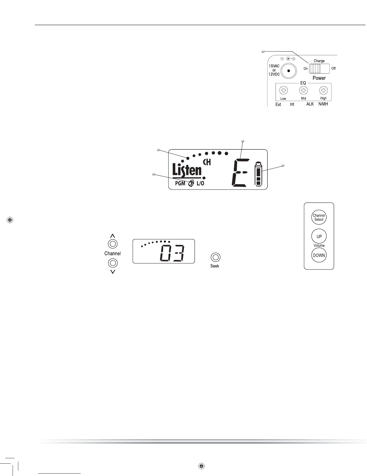
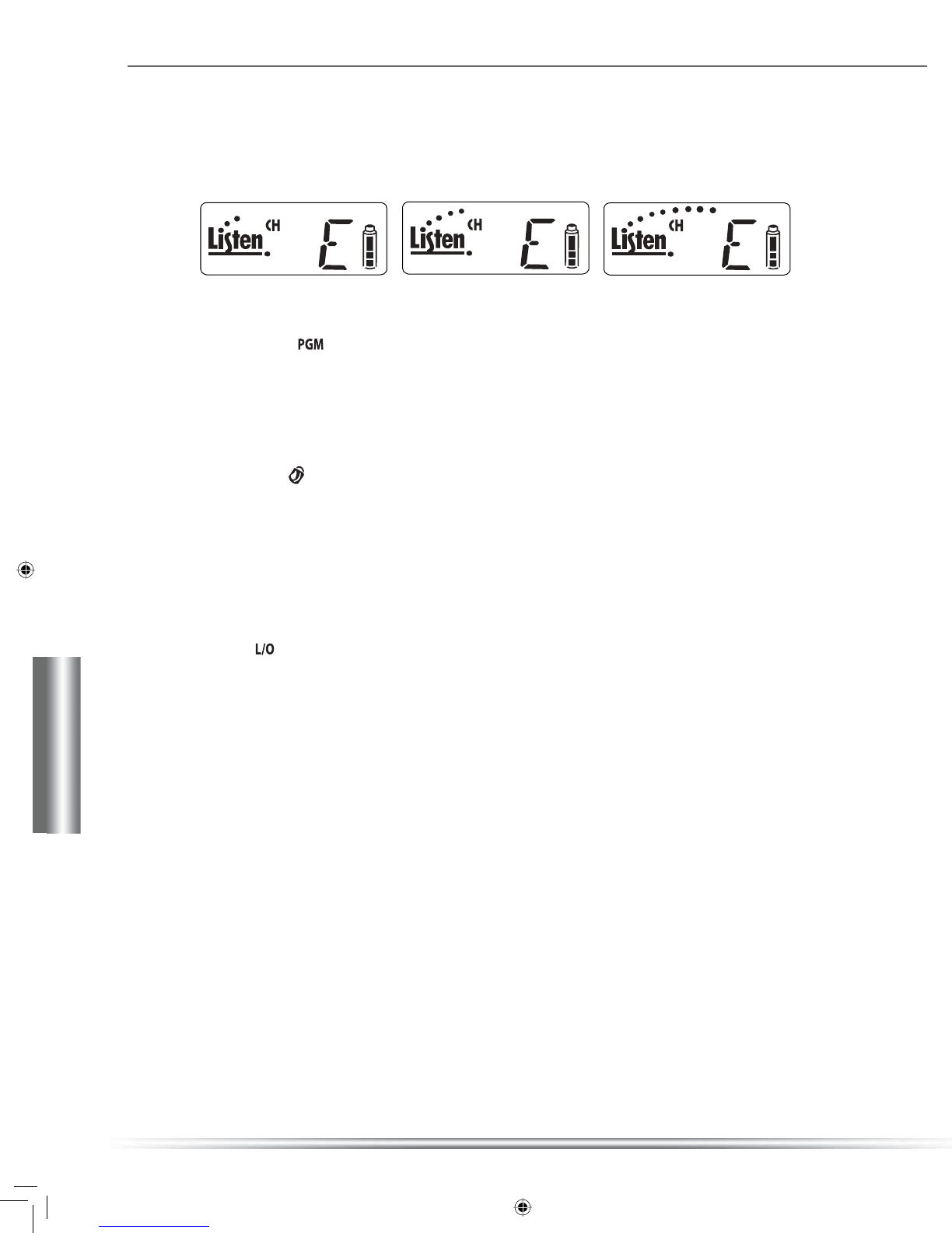
The device will incorporate a backlit LCD Display that indicates channel and RF signal strength,
as well as be used for channel selection programming. The unit shall be programmable to
display only used channels. It shall also incorporate an electronically lockable volume and
channel controls. Controls should be found on the top and rear of the unit. The device shall
incorporate a power supply (120 VAC, 60 Hz, 43 Watts), with output DC 12V 2500 mA tip
negative. It will alternately use an internal battery pack using eight AA alkaline or NiMH
Rechargeable batteries and include recharging components for said NiMH batteries. The
speaker should have a minimum SPL of 110dB (±3dB). An included bracket will be able to be
used as a handle for carrying, or be adjustable up to 360 degrees around the unit for mounting.
The Listen LR-600 is specified.
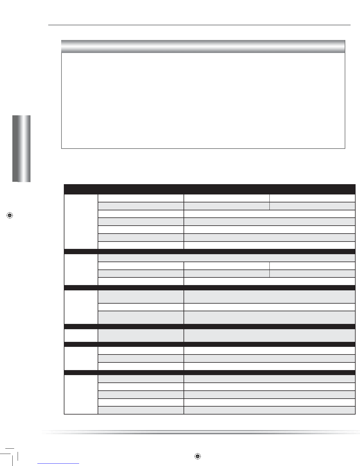
Specications LR-600-072 LR-600-216
RF
RF Frequency Range 72.025 - 75.950 MHz 216.025 - 216.975 MHz
Number of Channels 57 (17 wide, 40 narrow) 57 (19 wide, 38 narrow)
Frequency Accuracy +/- .005% stability 0 to 50C
Antenna (Internal) Comes with Internal Antenna
Antenna (External) Several available. See www.ListenTech.com for details
Antenna Connector (External) BNC
Compliance FCC Part 15, Industry Canada
Audio
** All system specications are wireless end-to-end
System Frequency Response 63Hz - 15kHz (±3dB) 63Hz - 10kHz (± 3dB)
System Signal to Noise Ratio (Aweighted) SQ enabled: 80dB; SQ disabled: 60dB SQ enabled: 80dB; SQ disabled 50dB
System Distortion <2% total harmonic distortion (THD) at 80% deviation
Controls
Set Up Controls Programmable channel selection and squelch. Batteries (alkaline/NiMH), SQ
(enable/disable), Antenna (internal/external), Equalization POT’s (Low/Mid/High)
User Controls Volume, channel up/down/seek.
Programming Can be programmed so that only desired channels are selectable by user. Squelch can also
be adjusted. Channel selection can be locked by holding the SEEK button for 5 seconds.
Indicators LCD Display Indicates channel, battery power level, lock status, RF signal strength and channel
programming.
Power
Battery Type Eight AA batteries, alkaline or NiMH
Power Supply Connector 15VAC, 1000mA; .02 in (5.0mm) OD x .01 in (2.5mm) ID, barrel
Compliance UL Listed
Physical
Dimensions 11 in. x 9.5 in. x 6 in.
Unit Weight 6 lbs.
Unit Weight with batteries 6.5 lbs.
Shipping Weight 10 lbs. (includes power supply)
Battery Compartment On rear of unit behind access door.
LR-600 Specifications
Architectural Specifications
Specication
LR-600 manual_2006_04_12.indd Sec1:4LR-600 manual_2006_04_12.indd Sec1:4 4/16/2007 11:04:14 AM4/16/2007 11:0

5
Power
O/Change/On
+12VDC or
18VAC
External
Power Supply
18VAC UL
Listed
115VAC
ALK
Receiver
RF Board
10/7 Watt
(peak/RMS)
Power Amp
Listen LCD Display
(backlighted)
Crossover
Network
LR-600 Block Diagram
LR-600 Wireless Speaker/ Receiver
Block Diagram
©Listen Technologies Corporation
2007409
LR-600 manual_2006_04_12.indd Sec1:5LR-600 manual_2006_04_12.indd Sec1:5 4/16/2007 11:04:16 AM4/16/2007 11:0

6
Quick Reference
EXTERNAL ANTENNA:
If you need more receiving
range, connect an external
antenna here. Antennas
are available from Listen.
POWER: Connect the
(included) power supply
here, or a +12VDC power
source such as a vehicle
power adapter.
EQ: Three-band
equalizer used to
adjust sound quality
to meet your needs.
ON / CHARGE / OFF:
To operate and charge batteries,
move to ON position. To only
charge batteries, move to CHG
position. See page 16.
AUXILIARY CONNECTORS:
To listen to a CD, TV, etc
through the speaker,
connect to AUX IN. To route
receiver audio to an external
device such as a recorder or
mixer, connect to Aux out.
SQ MODE: When ON,
activates the Listen SQ™
mode, improving noise
performance by better than
20dB. Transmitter must also
have SQ enabled to use
this mode.
EXTERNAL SPEAKER:
Connect an external
speaker here.
CHANNEL UP / DOWN and SEEK:
Use to select and search
channels, or to program the unit.
BATTERY COMPARTMENT:
Remove access panel to change
batteries. Unit holds eight
optional AA batteries (NiMH
rechargeable or alkaline).
LCD PANEL:
See below
ANTENNA SELECT:
If you connect an
external antenna, move
this switch to EXT. If
no external antenna is
used, the switch should
be on INT.
RF Signal Strength
PGM: Indicates the unit is
in the program mode that
allows you to lock out
channels that are not used.
LOCK: When the padlock icon is visible,
the channel buttons are locked and you
cannot change the channel. When the
padlock is flashing, both the channel
and volume buttons are locked. To lock
channels, press and hold SEEK for 5
seconds. Repeat to unlock. To lock
channels and volume, press SEEK and
then the UP button. Press SEEK and then
DOWN to unlock.
Indicates channel, or when volume up or down
button is pressed, indicates volume.
L/O: When in the programming
mode, this symbol indicates the
channel is locked out and will
not be displayed tothe user.
CHANNEL SELECT:
Selects the next
programmed
channel.
VOLUME:
Adjusts volume up
and down.Volume
setting of 0 to 26
is indicated on
rear panel LCD.
LR-600 LCD Panel Details
LR-600 Rear Panel: Connections and Controls
LR-600 Quick Reference
LR-600 Top Panel Details
LR-600 manual_2006_04_12.indd Sec1:6LR-600 manual_2006_04_12.indd Sec1:6 4/16/2007 11:04:18 AM4/16/2007 11:0

7
Power the unit ON
Turn the unit on by sliding the power switch on the rear of the unit to the
On position. The LCD will activate; if using the LR-600 on the power
supply, the LCD backlight will activate and remain on. If you are using
the unit on batteries, the LCD backlight will operate for 12 seconds after
any button is pressed, and then dim to conserve battery life.
Padlock Icon
Battery
Control panel (rear of unit) Control panel
(top of unit)
LCD Display
Once the unit is on, the LCD display will illuminate. Notice that when the unit is
in operation on the power supply, the LCD backlight will remain lit continuously.
When on battery power, the backlight will remain lit for 10 seconds after any
button is pushed. This is designed to save battery life.
Volume Control
Adjust the volume setting for a comfortable level by pressing the VOLUME UP and
DOWN buttons on the top of the unit. The volume setting (a number between 0
and 26) will be shown on the display. To lock the volume setting see page 14.
Channel Selection
To select a program channel, press the Channel Select button on the top of
the unit. To program this function see page 13. If channels have not been
programmed, the unit will step through all available channels as you repeatedly
press the CHANNEL SELECT button. If channels have been programmed, you may
wish to use the Seek button on the rear panel instead. Pressing Seek will cause the
LR-600 to search for an available transmission. You may also use the Channel UP
and DOWN buttons on the rear panel to step through the channels available to
the LR-600.
Battery Icon
The battery icon shows the amount of battery life remaining in full, ½, ¼ and
flashing increments (indicating low battery). When charging, the battery icon
changes through all of these states to show it is charging. See page 11 for
complete battery information.
LR-600 Operation
Signal Strength
Channel or Volume
LR-600 manual_2006_04_12.indd Sec1:7LR-600 manual_2006_04_12.indd Sec1:7 4/16/2007 11:04:40 AM4/16/2007 11:0

8
Setup/IProgramming
Low RF
Signal
Signal Strength
Just as on your cellular telephone, the dots above the Listen logo show the RF
signal strength coming from the transmitter.
Program Icon
When lit the Program icon indicates the unit is in the program mode that allows you to
lock out channels that are not used.
Padlock Icon
If illuminated, indicates the channel selection function is locked. If flashing, indicates the
channel selection and volume control functions are locked. See page 14 for more information.
Lock Icon
When the padlock icon is visible, the channel buttons are locked and you cannot change the
channel. When the padlock is flashing, both the channel and volume buttons are locked. To
lock channels, press and hold SEEK for 5 seconds. Repeat to unlock. To lock channels and
volume, press SEEK and then the UP button. Press SEEK and then DOWN to unlock.
Medium RF
Signal
High RF
Signal
LR-600 Operation (cont.)
LR-600 manual_2006_04_12.indd Sec1:8LR-600 manual_2006_04_12.indd Sec1:8 4/16/2007 11:04:53 AM4/16/2007 11:0

9
Power Supply (included with unit)
If you are using the LR-600 with the external power supply, connect the power supply to the
LR-600 and plug the power supply into a 115VAC/60 Hz outlet.
External +12VDC Source
If you are using the LR-600 with an external +12VDC battery or power supply, obtain a power
connector with following dimensions:
0.098 in. (2.5 mm) inside diameter
0.217 in. (5.5 mm) outside diameter
0.374 in. (9.5 mm) length
Wire the connector so the tip is positive. Connect to a 12VDC battery or +12VDC output of a power supply.
LR-600 Power/Battery Options
LR-600 manual_2006_04_12.indd Sec1:9LR-600 manual_2006_04_12.indd Sec1:9 4/16/2007 11:04:55 AM4/16/2007 11:0

10
Setup/IProgramming
IMPORTANT: You must place the Battery switch in the appropriate position for the type of batteries you
will be using. If you are using alkaline batteries and the switch is in the NiMH position, the
unit will attempt to charge the batteries when connected to a power supply or external
battery. Attempting to charge alkaline batteries can result in permanent damage to the
unit, and the batteries may explode. Damage resulting from attempting to charge alkaline
batteries will void the warranty.
Internal Batteries
If you are using the LR-600 with internal batteries, do the following:
Open the battery compartment by removing the
thumbscrew and then removing the cover.
Slide the battery holder out of the battery compartment.
Install eight AA alkaline or NiMH batteries with polarity
noted on the battery holder.
Replace the battery holder and secure the battery
compartment cover.
IMPORTANT: Slide the battery switch to the alkaline or NiMH
battery position depending on the battery type
you are using.
LR-600 Power/Battery Options (cont.)
LR-600 manual_2006_04_12.indd Sec1:10LR-600 manual_2006_04_12.indd Sec1:10 4/16/2007 11:05:00 AM4/16/2007 11:0

11
Battery Charging
For NiMH battery operation, you must charge the batteries for 13 hours before use. To
charge the batteries, plug the unit into the power supply or external +12VDC supply and
move the power switch to either CHG or ON. The batteries will charge in either position.
In Charge mode, the battery symbol
will cycle between low, mid and full.
When the batteries are charging, the battery icon changes from ¼ to ½
to full and then repeats to indicate charging.
When not using the unit, it is advisable to leave the unit connected to
the power supply to keep the batteries fully charged. This will not
damage the batteries.
When the batteries are fully charged, the unit will automatically shut off.
To reactivate the unit, turn the unit OFF and then back ON.
NOTE: During battery operation, if the battery icon begins flashing
on the Low level (one bar showing), your batteries are almost
exhausted and shutdown is imminent. Connect to a power supply
or replace the batteries.
LR-600 Battery Charging
LR-600 manual_2006_04_12.indd Sec1:11LR-600 manual_2006_04_12.indd Sec1:11 4/16/2007 11:05:11 AM4/16/2007 11:0

12
Setup/IProgramming
The LR-600 has two antenna options: internal or external. On 72 MHz units,
connecting a helical external antenna (LA-123) will double your range
(approximately). 216 MHz units have a much more efficient internal antenna
so range is minimally increased by adding a helical external antenna
(LA-124). To use the internal antenna, move the antenna switch to Int. To
use the external antenna, move the switch to Ext.
Internal antenna
As shipped, your LR-600 is set up for use with its internal antenna. The internal antenna will
work well for a large number of uses, but it cannot be positioned for best coverage. When
using the LR-600’s internal antenna, make sure the antenna switch is in the Int position. If
your receive signal is noisy or weak, you may need to use an external antenna.
External antennas
To use an external antenna with the LR-600 the Antenna switch on the rear of the unit
must be set to Ext (see illustration below).
There are four options for the external antenna:
LA-123 (72 MHz) or LA-124 (216 MHz) 90 Degree Helical Antenna
This antenna mounts directly to the back of the LR-600. (Shown below)
LA-122 Universal Antenna Kit (72 and 216 MHz)
This remote antenna contains both 72MHz and 216MHz antennas in monopole and dipole
options. Includes all hardware to mount on a wall, electrical box or on a
horizontal surface as well as, 25 feet (7.6 m) of
RG-58 coaxial cable.
LA-107 Ground Plane Remote
Antenna (216 MHz)
¼ wave antenna designed for
outside mast or conduit mounting.
Includes 50 feet (15.25 m) RG-58
coaxial cable.
LA-116 (72 MHz) or LA-117
(216 MHz) Coaxial Dipole
Remote Antenna
Flexible coaxial cable antenna
that can be mounted on a wall or
placed in a drop ceiling. Includes 25
feet (7.6 m) RG-58 coaxial cable.
NOTE: See page 30 for complete
descriptions and illustrations of
antenna options.
EQ
LR-600-216 shown with LA-124 (216 MHz) antenna
LR-600 Antenna Options
1
2
3
4
LR-600 manual_2006_04_12.indd Sec1:12LR-600 manual_2006_04_12.indd Sec1:12 4/16/2007 11:05:15 AM4/16/2007 11:0

13
Power the unit ON
Turn the unit on by sliding the power switch on the rear of the unit to the On position.
Channel Selection
Using the channel select buttons (UP and DOWN buttons on the rear panel) or the SEEK
button, select the desired receive channel. For more information, see Channel Selection
on page 23.
Locking Channel Selection
If you don’t want the user to have the ability to change the channel, it is highly recommended
that you lock the channel select function. This is accomplished as follows:
Press and hold the SEEK button for 5 seconds.
The padlock icon will appear in the display.
To unlock the channel selection function, press and hold the SEEK button until the
padlock icon goes out.
EQ
LR-600 Setup and Programming
LR-600 manual_2006_04_12.indd Sec1:13LR-600 manual_2006_04_12.indd Sec1:13 4/16/2007 11:05:26 AM4/16/2007 11:0

14
Setup/IProgramming
EQ
LR-600 Setup and Programming (cont.)
Locking the Unit on a Channel
Once the desired channel has been selected, you can lock the channel select buttons
as follows:
Press and hold the seek button for 5 seconds
The padlock icon will illuminate solid on the rear panel LCD display
To unlock, press and hold the seek button for 5 seconds.
Locking both Volume and Channel
Once the desired channel and volume has been set, both functions can be locked as
follows:
Press the seek and channel up button simultaneously
The padlock icon will flash on the LCD display
To unlock, press the seek and channel down button simultaneously
Setting the SQ Switch
For more information on SQ, see Listen SQ™ on page 21.
The SQ function improves the noise performance of the LR-600 by at least 20dB. To use
this function, the transmitter must also be a Listen brand transmitter with SQ.
To use the SQ function, do the following:
Verify the transmitter has SQ and the SQ function is turned on.
Move the SQ switch on the back of the unit to the ON position.
If you are using the LR-600 with another brand transmitter or if you don’t want to
use the SQ function, move the SQ switch to the OFF position.
LR-600 manual_2006_04_12.indd Sec1:14LR-600 manual_2006_04_12.indd Sec1:14 4/16/2007 11:05:34 AM4/16/2007 11:0

15
Programming the Channel Select Button
The channel select button on the top of the unit is designed to give users the ability to choose
between different channels. If you don’t want to give users this function, it is recommended
that you lock this feature as described on page 13.
If you want to use this function, you must program the unit for the channels you are using. For
example, you are using 72 MHz channels A, E and I. You would only want the LR-600 to receive
on channels A, E, and I. When the Channel Select button has been programmed, the unit will
select A the first time the user presses the button; when the user presses the button successively,
E will be selected, then I, then A again.
Note: The UP button on the rear panel and Channel Select button on the top of the unit
perform the same function for end users.
To program the unit so that it only receives on certain channels, do the following:
Press the UP and DOWN buttons together and release. The PGM icon is displayed.
Press the UP or DOWN button to select channels.
When you get to a channel that you don’t want displayed, press the SEEK button.
The L/O icon will be displayed indicating the channel is locked out and will not
be displayed.
Repeat for all channels that you want locked out.
When done, don’t press a button for 10 seconds and the unit will return to normal operation.
Press the Channel UP and DOWN buttons at the same
time to enter Program mode (shown by the PGM icon).
While in Program mode, press SEEK to lock out a
channel that you do not want available to the end user.
L/O will show on the display.
LR-600 Setup and Programming (cont.)
LR-600 manual_2006_04_12.indd Sec1:15LR-600 manual_2006_04_12.indd Sec1:15 4/16/2007 11:05:52 AM4/16/2007 11:0

16
Setup/IProgramming
The purpose of the equalizer is to adjust the sound quality to your specific needs and taste.
Use a small screwdriver to adjust the LOW, MID and HI positions. These correspond to the
following center frequencies: 250 Hz, 1 kHz and 4 kHz.
Adjust to the center position to make the frequency response flat.
LR-600 Equalization Adjustment
LR-600 manual_2006_04_12.indd Sec1:16LR-600 manual_2006_04_12.indd Sec1:16 4/16/2007 11:06:09 AM4/16/2007 11:0

17
When the transmitter is not turned on, the squelch function mutes the audio so that
random noise is not heard through the speaker.
The squelch function can be programmed for more or less sensitivity. When the squelch
function is programmed for more sensitivity, you sacrifice transmission range in exchange
for more reliability of the squelch function. When the squelch function is programmed for
less sensitivity, you achieve greater transmission range in exchange for less reliability of the
squelch function. This means that even if the transmitter is off, you may hear noise in the
speaker. You can try different squelch settings for your application.
Examples for setting the squelch sensitivity high
You absolutely don’t want the unit to have noise when the transmitter is off.
The transmitter is close to the LR-600.
Examples for setting the squelch sensitivity low
It doesn’t matter if the user hears the noise if the transmitter is turned off.
The transmitter is located a long distance from the LR-600.
The adjustable squelch can be programmed from 0 (no squelch) to a maximum of 20
(highest sensitivity). The default setting is 3.
To program the squelch setting, do the following
Turn the unit off.
Press and hold the SEEK button.
Turn the unit on.
Release the SEEK button.
The squelch setting is shown on the display. Default is 3.
Use the UP and DOWN buttons on the rear panel to select the setting you want.
Note the RF meter still operates, giving you relative RF power from the transmitter.
When you are done, press SEEK to store the new squelch setting.
Use Seek to enter Squelch
programming mode and to save
settings (see instructions above).
While in Squelch programming mode,
channel UP / DOWN buttons are used
to change squelch sensitivity. 03 is
the factory default.
LR-600 Squelch Adjustment
LR-600 manual_2006_04_12.indd Sec1:17LR-600 manual_2006_04_12.indd Sec1:17 4/16/2007 11:06:10 AM4/16/2007 11:0

18
Setup/IProgramming
Additional audio can be mixed with the received audio from the
transmitter and sent to the speaker. This can be accomplished by using the
auxiliary input connections. Take the audio output of your device (such as a
CD player, TV or computer) and connect it to the two
input phono connectors of the LR-600.
The auxiliary output phono connectors can be used
to take the received audio from the LR-600 to send to
a mixer, recorder or other device. The audio being
output on these connectors is the received audio only.
The audio from the auxiliary input is not present at the
auxiliary output. This is done to allow cross-feeding of
multiple LR-600’s, as described below.
Cross-Connecting LR-600’s
Multiple LR-600’s can be cross connected to allow audio from multiple
transmissions to be heard on all connected LR-600’s. For example:
You have (2) transmitters operating simultaneously on different
channels and (2) LR-600’s picking up each transmission channel
separately. If you wish to be able to hear both transmissions on
both LR-600’s, this can be done by cross connecting the units as
show below.
The audio being input to an LR-600 will not be present on the
audio output. Only the received audio from the transmitter will
be output on the LR-600. This is done to allow cross connecting
without creating an audio loop. If units are cross connected and
auxiliary audio from another device such as a CD player or
computer is input, that audio will only be heard on that LR-600.
LR-600 External Speaker (optional)
You can connect an external speaker to the LR-600. Make sure
that the speaker is 4 ohms or greater. The Listen LA-316 speaker
provides the same look as the LR-600.
Connect auxiliary phono
cables here.
An external speaker (4 ohms or greater) may
be connected to the speaker terminals below
the LCD panel.
EQ
EQ
LR-600 Auxiliary Input and Output
LR-600 manual_2006_04_12.indd Sec1:18LR-600 manual_2006_04_12.indd Sec1:18 4/16/2007 11:06:33 AM4/16/2007 11:0
Other manuals for LR-600
1
Table of contents
Other Listen Receiver manuals

Listen
Listen LR 500 User manual

Listen
Listen LR-300 User manual

Listen
Listen LR-42 Reference guide

Listen
Listen LR-300-072 Reference guide

Listen
Listen LR-5200-072 User manual

Listen
Listen LR-500-216 Reference guide

Listen
Listen LR-400-072 Reference guide

Listen
Listen LR-200-072 Reference guide

Listen
Listen LR-400-150 Reference guide

Listen
Listen LR 500 User manual