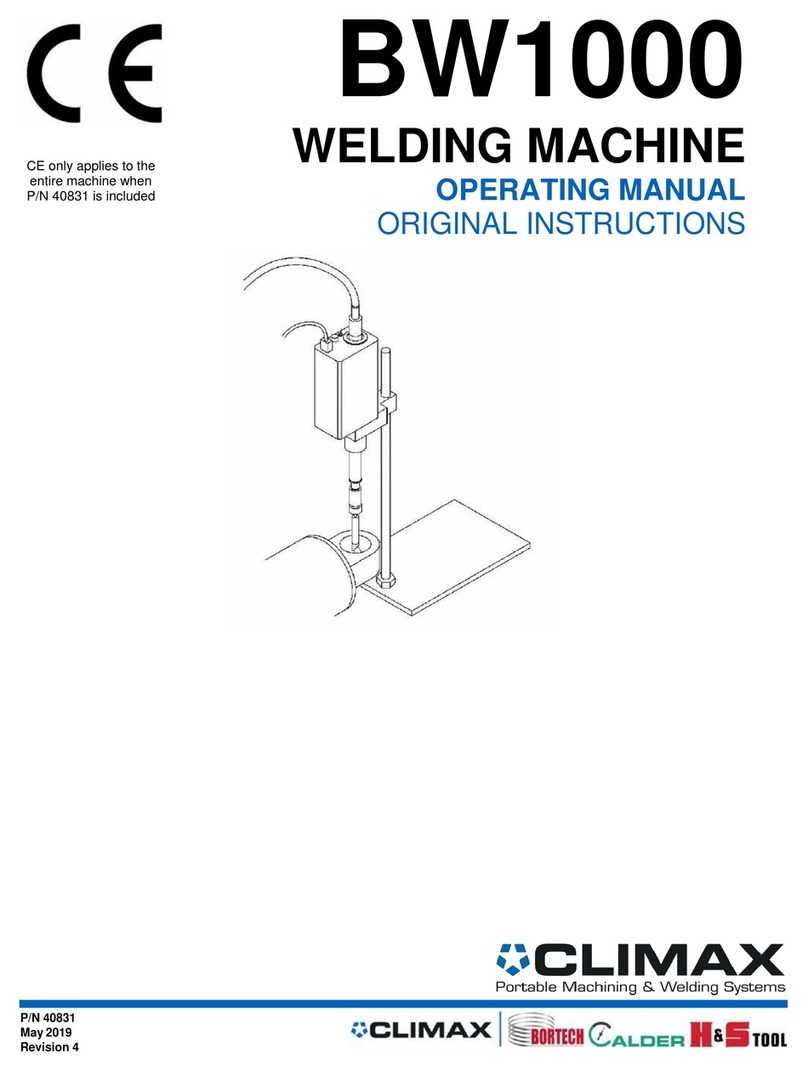
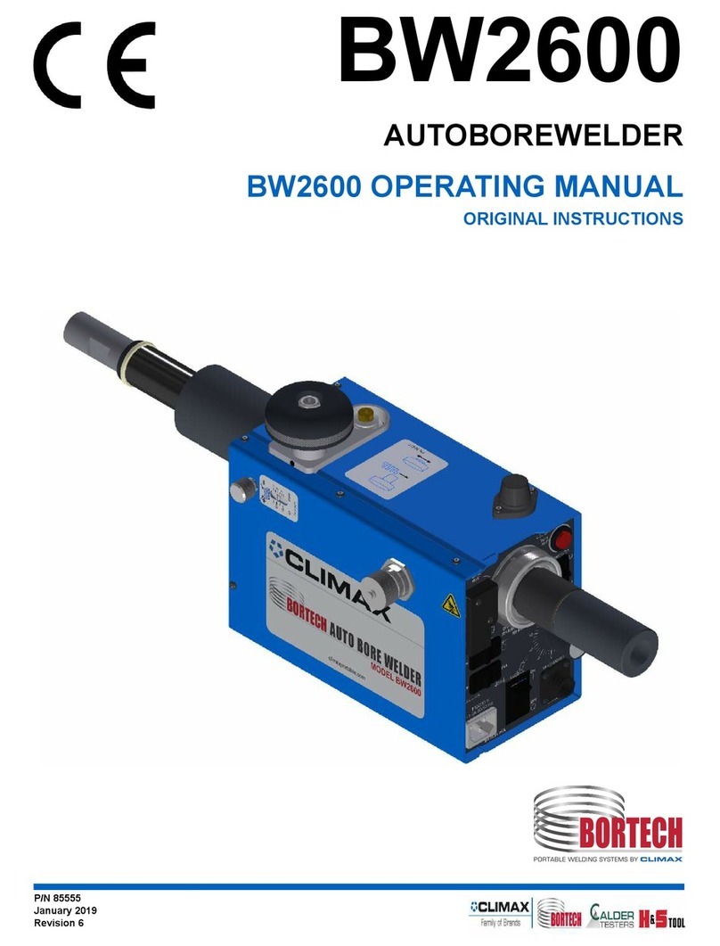
Climax BW5000 User manual

P/N 68191
May 2019
Revision 4
BW5000
AUTOBOREWELDER
OPERATION MANUAL
BW5000 AutoBoreWelder


P/N 68191, Rev. 4 Page i
Table of Contents
Safety Precautions..................................................................................................................... 1
Introduction ................................................................................................................................ 7
Product Features ......................................................................................................................11
Specifications............................................................................................................................12
Major Assemblies......................................................................................................................14
Receiving the Machine..............................................................................................................18
Setup of the BW5000................................................................................................................20
Operation of BW5000................................................................................................................38
Optional Equipment – Description and Use...............................................................................41
Maintenance and Adjustments ..................................................................................................43
Configuration Line Drawings .....................................................................................................46
Shipping and Storage................................................................................................................53
Recommended Spare Parts ......................................................................................................54
Exploded Views and Parts Lists ................................................................................................55
Schematics .............................................................................................................................114
Quick Reference Charts..........................................................................................................117
W
WA
AR
RN
NI
IN
NG
G
For maximum safety and performance, read and understand the entire manual
and all related safety instructions before using this equipment. Failure to follow
the instructions and guidelines in this
manual could cause personal injury,
fatalities or property damage.

Page ii BW5000 Operating Manual
This page is intentionally left blank

P/N 68191, Rev. 4 Page 1
Safety Precautions
The primary challenge for most on-site maintenance is that repairs are often done under difficult
conditions.
Climax Portable Machining and Welding Systems, Inc. leads the way in promoting the safe use
of portable machine tools. Safety is a joint effort. As the operator of this machine, you are
expected to do your part by scrutinizing the job site and closely following the operating
procedures outlined in this manual, your own company rules, and local regulations.
General Safety Practices
QUALIFIED PERSONNEL
Before operating this machine, you must receive
training specific to this machine from a qualified
trainer. If you are not familiar with the proper and
safe operation, do not use the machine.
OBEY WARNING LABELS
Obey all warnings and warning labels. Failure to
follow instructions or heed warnings could result
in injury, or even be fatal. Proper care is your
responsibility. Contact Climax immediately for
replacement of damaged or lost manuals or
safety decals. 1-800-333-8311
INTENDED USE
Only use the machine according to the
instructions in this operating manual. Do not use
this machine for any purpose other than the
intended use as described in this manual. When
using the tools, machine, accessories and/or
tool bits, you must determine the proper working
conditions and the work to be performed.
STAY CLEAR OF MOVING PARTS
Keep clear of the machine during operation.
Never lean toward or reach into the machine to
remove chips or to adjust the machine while it is
running. Keep bystanders away while operating
this machinery.
ROTATING MACHINERY
Rotating machinery can seriously injure an
operator. Lock out all power sources before you
interact with the machine.
KEEP YOUR WORK AREA CLEAN AND TIDY
Keep all cords and hoses away from moving
parts during operation. Do not clutter the area
around the machine. Keep the work area clean
and well lit.
AMBIENT LIGHTING
Do not operate this machine in ambient lighting
that is less than normal intensity.
SECURE LOOSE CLOTHING AND LONG HAIR
Rotating machinery can seriously injure an
operator as well as others close by. Don’t wear
loose fitting clothing or jewelry. Tie back long
hair or wear a hat.
HAZARDOUS ENVIRONMENTS
Do not use the machine in a hazardous
environment, such as near explosive chemicals,
flammable liquids, gasses, toxic fumes, or
radiation hazards.
HOSES, PENDANT AND ELECTRICAL CABLES
Do not abuse the pendant cable as this can
damage the cable and pedant. Never use the
cord for carrying, pulling or unplugging. Remove
any and all kinks before straightening the cable.
Keep cords and hoses away from heat, oil,
sharp edges or moving parts. Plugs must match
the outlet. Never modify the plugs in any way.
Do not use an adapter plug with grounded
power tools. Do not expose the machine to rain
or wet conditions. Always examine hoses and
cables for damage before use. Be cautious and
never drop electrical equipment, this will
damage the components.
REPETITIVE MOTION
Individuals can be susceptible to disorders of the
hands and arms when exposed to tasks that
involve highly repetitive motions and/or vibration.
STAY ALERT
Stay alert, watch what you are doing and use
common sense when operating machinery. Do
not operate machinery while you are tired or
under the influence of drugs, alcohol or
medication.

Page 2 BW5000 Operating Manual
Machine Specific Safety Practices
All aspects of the machine have been designed with safety in mind. Rotating parts are not
always shielded by machine components or by the work piece. Do not force the machine.
PERSONAL PROTECTIVE EQUIPMENT
Eye and hearing protection must be worn while
using the machine. These safety items do not
impose constraints to the safe operation of the
machine.
OPERATING CONDITIONS
Do not operate the machine if it is not mounted to
the work piece as described in this manual.
TOOLING
The machine is provided with all the tools for the
setup and operation of the machine. Remove all
adjustment tools before starting the machine.
LIFTING
Most of the machine components are heavy and
must be moved or lifted with approved rigging and
practices. Climax accepts no responsibility for the
selection of lifting equipment. Always follow your
plant’s procedures for lifting heavy objects. Do not
lift heavy objects by yourself as serious injury can
result.
CUTTING TOOLS AND FLUIDS
There are no cutting or cooling fluids supplied with
this machine. Keep cutting tools sharp and clean.
CONTROLS
The machine controls are designed to withstand
the rigors of normal use and external factors. The
on-off switches are clearly visible and identifiable.
If hydraulic power supply failure occurs, be sure to
turn off the supply before leaving the machine.
DANGER ZONE
The operator and other persons can be anywhere
in the vicinity of the machine. The operator must
ensure there are no other persons in danger from
the machine.
METAL FRAGMENT HAZARD
The machine produces metallic fragments during
normal operation. You should wear eye protection
at all times when working with the machine. Only
remove fragments with a brush after the machine
has stopped completely.
RADIATION HAZARDS
There are no systems or components on this
machine that are capable of producing hazardous
EMC, UV or other radiation hazards. The machine
does not use lasers nor does it create hazardous
materials such as gasses or dust.
ADJUSTMENTS AND MAINTENANCE
All adjustments, lubrication and maintenance
should be done with the machine stopped, and
locked out from all power sources. The shut-off
valves should be locked and tagged out before
performing any maintenance. Do not operate the
machine if moving parts are misaligned, binding or
broken. If the machine or parts are damaged,
have the machine repaired before use.
WARNING LABELS
Warning labels are already attached to your
machine. Contact Climax immediately if
replacements are required.
MAINTENANCE
Be sure the machine components are free of
debris and properly lubricated prior to use. Have
your machine serviced by a qualified repair
person using only identical replacement parts.
NOISE LEVEL
85 dB(A) or higher – Hearing Protection is
required.
STORED ENERGY
Hydraulic fluids could still be under pressure!
Make sure the HPU is shut off and locked out
properly.
MSDS
Material Data Safety Sheets are included in the
maintenance manual.
UNINTENTIONAL STARTING
Prevent unintentional starting. The machine must
be properly locked out and/or shut down before
maintenance.

P/N 68191, Rev. 4 Page 3
Safety Sign and Symbol Guidelines
The purpose of product safety signs and symbols is to increase the level of awareness to
possible dangers.
Safety alert symbols indicate DANGER, WARNING or CAUTION. These symbols may be used
in conjunction with other symbols or pictographs. Failure to obey safety warnings can result in
serious injury or death. Always follow safety precautions to reduce the risk of hazards and
serious injury.
D
DA
AN
NG
GE
ER
R
Indicates a hazardous situation that could be fatal or cause serious injury.
W
WA
AR
RN
NI
IN
NG
G
Indicates a potentially hazardous situation that could be fatal or cause serious
injury.
C
CA
AU
UT
TI
IO
ON
N
Indicates a potentially hazardous situation that could result in minor to
moderate injury, damage to the machine or
interruption of an important
process.
I
IM
MP
PO
OR
RT
TA
AN
NT
T
Provides critical information for the completion of a task. There is no
associated hazard to people or the machine.
I
IN
NF
FO
OR
RM
MA
AT
TI
IO
ON
N
Provides important information regarding the machine.

Page 4 BW5000 Operating Manual
Risk assessment and hazard mitigation
Machine Tools are specifically designed to perform precise material-removal operations.
Stationary Machine Tools include lathes and milling machines and are typically found in a
machine shop. They are mounted in a fixed location during operation and are considered to be
a complete, self-contained machine. Stationary Machine Tools achieve the rigidity needed to
accomplish material-removal operations from the structure that is an integral part of the machine
tool.
In contrast, Portable Machine Tools are designed for on-site machining applications. They
typically attach directly to the workpiece itself, or to an adjacent structure, and achieve their
rigidity from the structure to which it is attached. The design intent is that the Portable Machine
Tool and the structure attached to it become one complete machine during the material-removal
process.
To achieve the intended results and to promote safety, the operator must understand and follow
the design intent, set-up, and operation practices that are unique to Portable Machine Tools.
The operator must perform an overall review and on-site risk assessment of the intended
application. Due to the unique nature of portable machining applications, identifying one or more
hazards that must be addressed is typical.
When performing the on-site risk assessment, it is important to consider the Portable Machine
Tool and the workpiece as a whole.

P/N 68191, Rev. 4 Page 5
Risk assessment checklist
Use these checklists as part of your on-site risk assessment and include any additional
considerations that may pertain to your specific application.
TABLE 1. RISK ASSESSMENT CHECKLIST BEFORE SET-UP
Before Set-up
I took note of all the warning labels on the machine.
I removed or mitigated all identified risks (such as tripping, cutting, crushing,
entanglement, shearing, or falling objects).
I considered the need for personnel safety guarding and installed any
necessary guards.
I read the Machine Assembly instructions and took inventory of all the items
required but not supplied.
I created a lift plan, including identifying the proper rigging, for each of the
setup lifts required during the setup of the support structure and machine.
I located the fall paths involved in lifting and rigging operations. I have taken
precautions to keep workers away from the identified fall path.
I considered how this machine operates and the best placement for the
controls, cabling, and the operator.
I evaluated and mitigated any other potential risks specific to my work area.
TABLE 2. RISK ASSESSMENT CHECKLIST AFTER SET-UP
After Set-up
I checked that the machine is safely installed and the potential fall path is
clear. If the machine is elevated, I checked that the machine is safeguarded
against falling.
I identified all possible pinch points, such as those caused by rotating parts,
and informed the affected personnel.
I planned for containment of any chips or swarf produced by the machine.
I followed the maintenance intervals with the recommended lubricants.
I checked that all affected personnel have the recommended personal
protective equipment, as well as any equipment required by the site or other
regulations.
I checked that all affected personnel understand the danger zone and are
clear of it.
I evaluated and mitigated any other potential risks specific to my work area.

Page 6 BW5000 Operating Manual
LIMITED WARRANTY
CLIMAX Portable Machine Tools, Inc. (hereafter referred to as “CLIMAX”) warrants that all new
machines are free from defects in materials and workmanship. This warranty is available to the
original purchaser for a period of one year after delivery. If the original purchaser finds any
defect in materials or workmanship within the warranty period, the original purchaser should
contact its factory representative and return the entire machine, shipping prepaid, to the factory.
CLIMAX will, at its option, either repair or replace the defective machine at no charge and will
return the machine with shipping prepaid.
CLIMAX warrants that all parts are free from defects in materials and workmanship, and that all
labor has been performed properly. This warranty is available to the customer purchasing parts
or labor for a period of 90 days after delivery of the part or repaired machine or 180 days on
used machines and components. If the customer purchasing parts or labor finds any defect in
materials or workmanship within the warranty period, the purchaser should contact its factory
representative and return the part or repaired machine, shipping pre- paid, to the factory.
CLIMAX will, at its option, either repair or replace the defective part and/ or correct any defect in
the labor performed, both at no charge, and return the part or repaired machine shipping
prepaid.
These warranties do not apply to the following:
•Damage after the date of shipment not caused by defects in materials or
workmanship
•Damage caused by improper or inadequate machine maintenance
•Damage caused by unauthorized machine modification or repair
•Damage caused by machine abuse
•Damage caused by using the machine beyond its rated capacity
All other warranties, express or implied, including without limitation the warranties of
merchantability and fitness for a particular purpose are disclaimed and excluded.
Terms of sale
Be sure to review the terms of sale which appear on the reverse side of your invoice. These
terms control and limit your rights with respect to the goods purchased from CLIMAX.
About this manual
CLIMAX provides the contents of this manual in good faith as a guideline to the operator.
CLIMAX cannot guarantee that the information contained in this manual is correct for
applications other than the application described in this manual. Product specifications are
subject to change without notice.

P/N 68191, Rev. 4 Page 7
Introduction
This chapter contains important safety information, features, product description, basic
operation, and specifications. It also describes the parts of the BW5000.
The Climax BW5000 AutoBoreWelder was conceived of and designed by Climax engineering
personnel to satisfy the need for a portable machine to have the capability of rebuilding larger
bores as well as smaller bores.
Following the introduction of Climax BW3000 AutoBoreWelder, which can work in diameters
from 1/2 inch out to 54 inches (12.7 to 1371.6 mm), it became apparent that there was a
substantial requirement for a machine which would have diameter capabilities as great as 12
feet (3.75 M). Substantial input from field research and our own technical staff has resulted in
the BW5000 which combines ease of use, durability, and high deposition rates in a highly
refined product.
Climax manufactures functional welding equipment.
It is the buyer's responsibility to plan for the proper utilization of the equipment, including, but
not limited to:
•Developing the procedures to be used; qualifying the equipment operators to the
applicable codes and standards.
•Assuring the availability of power and gases at the point of utilization.
•Determining the equipment layout and sequencing for the specific conditions and
materials.
Climax can provide assistance in some of these areas, but does not take responsibility for them.
Training courses can be provided onsite and at Climax.
Arrangements must be made in advance, fees may apply.
Features
The Climax BW5000 AutoBoreWelder (hereafter referred to BW5000) is an automated
BoreWelding system with the following features:
•Portable system, allowing large circumferential part buildup without rotating the part.
•Modular “erector set” construction allows multiple configurations to suit varying job
requirements
•Wide range capacity, 2 feet to 12 feet (609.6—3657.6 mm) Inside Diameter and Face
buildup. Outside Diameter buildup up to10 feet (3048 mm)
•Heavy duty steel line bars and radial rods
•Feed lengths from 10 to 50 inches, 10 inch increments (254 to 1270 mm, 254 mm
increments)
•Variable angle 10 inch (254 mm) stroke feed mechanism for conical seats
•High current limit, 350 Amperes continuous, heavy duty power coupling
•Heavy duty torch mechanism, quick release system
•Reversible 4-roll Wire feed drive for added configurations

Page 8 BW5000 Operating Manual
•Wire capability from .035 to .062 (0.89 to 1.58 mm) solid, flux or metal core
•Rotating wire, torch and feed mechanism for added wire tracking consistency
•Leveling table for simple parallelism adjustment
•X and Y axis fine adjustment for simple centering adjustment
•Remote control pendant for management of all welding and operational parameters from
one location
Product Description & Basic Operation
The BW5000 is an automated welding device that consists of a rotating and axially stepping
MIG torch system in conjunction with a rotatable power coupling and slip ring system to build up
the surface of part.
The BW5000 is designed to MIG weld concentric inside diameters, faces and conical seats from
2 to 12 feet (609.6 to 3657.60 mm) in diameter, up to 60 inches (1524 mm) long, with stroke
lengths from 10 to 50 inches in 10 inch increments. Maximum outside diameter capability is 10
feet (3048 mm).
The part remains stationary and the BW5000 is supported from above by a customer supplied
frame, which suspends the BW5000 over the parts, providing a solid platform to make
necessary parallelism and centering adjustments of the BW5000 axis to the part axis.
Differences in weld diameter are accommodated by the Radial Rod selection, and differences in
feed length are accommodated by changes in Auxiliary Slide Guide Rods.
During the setup phase, the operator is required to:
•Set support frame up over the part.
•Install BW5000 on the support frame.
•Parallel and center the BW5000 Line Bar to the part
•Install and adjust the Radial rod, Aux Slide Guide Rod, Aux Stepping Unit, Torch
Mechanism, Wire feed Mechanism, Wire Reel support, Cables and Conduits to the
BW5000.
•Provide the proper torch/piece clearance.
•Verify clearance of installed parts on BW5000
•Make the initial control settings.
During welding, the operator is required to,
•To start and stop the machine.
•To observe the welding process.
•Make any adjustments in the rotational speed, voltage, wire speed, or step, necessary to
maintain good weld quality.
The BW5000 torch support mechanism allows for adjustment of torch to work piece angle and
lead/lag variation.
Typical weld mode is spray transfer.

P/N 68191, Rev. 4 Page 9
Safety
The BW5000 welding machine is designed for safety and ease of use in mind. As with operation
of any machinery, safe operation depends mainly upon the operator. The BW5000 requires
thoughtful, careful operation to produce optimum results and safety. This manual is an important
prerequisite in operating the BW5000 safely and effectively.
It is most important that the operator read and understand the specific instructions for set up
and operation of the BW5000 found in this manual, keeping in mind the following safety
information.
1. Set-up, maintenance, and operation of the BW5000 should only be accomplished by
qualified individuals.
2. Alterations to this machine must not be made without written approval from Climax
Corporation.
3. Any parts needed for special applications, alterations, repair or servicing must be
approved in writing by Climax to avoid creating hazardous conditions.
4. To assure that nothing gets caught in rotating members, avoid wearing loose fitting
clothing and keep hair back or in a cap when operating the machine
5. Turn off and lock out all power and release any residual energy sources before changing
torches or working on machines. (control, power supply, hydraulic pressure, etc.)
6. Read all instructions for the power supply unit you have chosen to use with the BW5000.
7. Should you have any questions, please call our Technical Service Department at 1-603-
358-4030
C
CA
AU
UT
TI
IO
ON
N
You must use protective eye wear, protective clothing, weld curtains, and
shields when using the BoreWelder to protect yourself and others from eye
and skin damage. Damage can result from both direct and indirect exposure to
arc rays.
Additional Welding Safety Precautions
1. The operator, and any personnel observing the machine when in use, must wear a
protective shield with a filter and cover plates which conform to ANSI Z87.1 Standards
2. The operator should wear protective clothing such as heavy shirts and cuffless pants of a
durable flame retardant material for protection from sparks and flame. Other personnel in
the area need to be protected from the arc rays by a screen and / or a warning not to
watch or otherwise expose themselves to the arc rays or any hot spatter.
3. Practice “good housekeeping” in the area around the BW5000. Keep combustibles or any
other fire hazards well away from the work area. Always have the properly rated fire
extinguisher readily available.
4. Welding may produce gases and fumes that are dangerous to breathe over prolonged
periods. Sufficient ventilation is needed to remove smoke and gases while the machine is
in use. The operator should not breathe welding fumes.

Page 10 BW5000 Operating Manual
5. Make the electrical installation in accordance with the National Electric code and all local
codes where applicable. Also, ground the Control box in accordance with above
mentioned codes by powering it only from properly grounded three prong outlets.
6. Caution must be taken with regard to potentially dangerous electrical shock. Do not ever
contact electrically live parts. Your hands can be insulated with dry hole free leather
gloves. When working in any damp areas or on metal floors, you must insulate yourself
from the ground and the work, making sure you have complete protection if you are
sitting or lying on the ground to operate the machine.
To obtain additional details on safety precautions, we highly recommend “Safety in Welding and
Cutting”, American National Standard ANSI Z49.1

P/N 68191, Rev. 4 Page 11
Product Features
Step Process
Step technology allows for complete weld coverage at the start and finish of the bore. Infinite
adjustment of step from .070” to .325” (1.78 to 8.26 mm) permits feed to be matched to weld
parameters. Precise control of step equals quality and consistency of weld deposit.
Fully Variable Torch Angle
The design of the BW5000 provides variable torch angle for maximum control of weld puddle.
This increases weld bead consistency with a wider range of weld metals and parameters.
Heavy Duty Torch System
The BW5000 brass body torch enables longer run times and longer consumable life, increasing
production and decreasing downtime.
Wire Feed System
The BW5000 Wire Feed system allows feeding of a wide range of exotic alloys. The modular
wire feeder allows multiple configurations, and is reversible for maximum capability.
Wire / Torch Stickout Adjustment
The Aux Torch Adjuster provides manual fine adjustment of wire stickout,
Auto Skip (optional)
Auto Skip allows automatic skipping of keyways, (up to 180 degrees of rotation), bidirectional
buildup (Pie Mode) of worn areas, or single direction buildup (Carriage Return) of worn areas
(under 180 degrees rotation).

Page 12 BW5000 Operating Manual
Specifications
BW5000 bore/ face range: 2 to 12 feet diameter (609.6 to 3657.6 mm)
Max. outside diameter: 10 feet diameter (3048 mm)
Stroke: 10, 20, 30, 40, 50 inches (254, 508, 762, 1016, 1270 mm)
Weight (head unit): 170 lbs. (77.1 kg)
Current Capacity: 350 amperes 100% duty cycle
Step Range: .070” to .325” (1.78 to 8.26 mm)
Torch Adjustment: 3 inches of stickout adjustment (76.2 mm)
Weld process: GMAW / FCAW
Weld Wire capacity: .035 to .062 (0.89 to 1.58 mm)
Control box power: 110 or 220 VAC 60/50 Hz (internal jumper)

P/N 68191, Rev. 4 Page 13
Figure 1 Major
Assemblies

Page 14 BW5000 Operating Manual
Major Assemblies
Mounting Plate
The Mounting Plate provides support for the BW5000, while also allowing for leveling and
centrality adjustment.
Head
The Head provides support and imparts rotary motion to the Line Bar via the Line Bar Coupling.
The Head imparts rotary motion to welding current, via Rotating Power Coupling, to Torch.
Shielding gas also travels via Rotating Power Coupling to the Wire feeder. The Wire feeder,
Step motor and Auxiliary motor current travel from the AMP connectors on the stationary side of
the Head, through a series of brushes in the head body, and are terminated at an AMP quick
disconnect fitting in the side of the Line Bar coupling at the lower part of the BW5000 head.
Line Bar
The Line Bar installs into the line bar coupling on the head assembly by means of a taper fitting.
Supports and orients the Radial Rod Mount, Radial Rod, and Aux Slide Guide Rod assemblies.
The Line Bar comes in 4 lengths, 12” (P/N 20236), 36” (P/N 20237), 72” (P/N 20238), and 96”
(P/N 20239). (304.8, 762, 1828.8, 2438.4 mm)
Radial Rod Mount, Junction Box
The Radial Rod Mount, Junction Box, (P/N A2034) is clamped in any location along the Line Bar
and provides a perpendicular attachment point for the Radial Rod. This clamping arrangement
allows for the coarse diameter adjustment by movement of the radial rod in the clamp
perpendicular to the line bar. The secondary function of this part is an electrical junction box,
interfacing with the AMP connector on the Line Bar Coupling. This junction is a central electrical
connection point for the wire feeder, step and auxiliary mechanism. The Junction Box also
houses the REVERSE / FORWARD switch for the wire feed drive.
Radial Rod
The Radial Rod provides support to the Aux Slide Guide Rod and Stepping Assembly, via the
90 degree block, (P/N 20207 Plain, P/N 20210 Keyed). The Radial Rods are tapped at each
end, for purposes of extending length, or attaching accessories. The 1”-8 NC (25.4 mm)
connector used for joining the Radial Rods is P/N 20077. The Radial Rods are available in 16”
(P/N 20224), 24” (P/N 20225), 38” (P/N 20226), and 60” (P/N 20227), lengths. (406.4, 609.6,
965.2, 1524 mm) These rods are different lengths for different diameter applications.
90° Block
The 90° Block (P/N 20207) attaches the Aux Slide Guide Rod in a perpendicular relationship to
the radial rod. The 90° Block, Keyed, (P/N 20210) is used when it is necessary to allow the rack
of the Aux Slide Guide Rod to slide through the block.
Aux Slide Guide Rod
The Aux Slide Guide Rod provides support to and a rack for the Aux Step Unit body and pinion.
Provided in 5 different stroke lengths to accommodate varying job requirements, 10” (P/N

P/N 68191, Rev. 4 Page 15
A2036), 20” (P/N A2037), 30” (P/N A2038), 40” (P/N A2039), 50” (P/N A2040). (254, 508, 762,
1016, 1270 mm)
Aux Stepping Unit
The Aux Stepping Unit provides linear movement along the Aux Slide Guide Rod for the Torch
Assembly. Once a full rotation is completed, the Aux Stepping Unit will move the value set at the
Control Box Step Knob. Step direction can be toggled at the control. The Step unit can be
removed and installed on other Aux Slide Guide Rods of different lengths. The Torch
attachment point on the Aux Step unit is electrically isolated from the Aux Stepping Unit chassis,
and subsequently from the rest of the BW5000. This feature prevents weld current from being
shunted to ground through the chassis of the BW5000.
See Removal and Installation of Aux Step Unit for best practices of removal and
installation.
Portable Wire Feeder
The Portable Wire feeder installs anywhere on the BW5000 Line Bar or Radial Rod. This
capability allows flexibility in placement of the drive mechanism, an advantage when varying job
requirements are at hand. To further this advantage, the Wire feeder is capable of being driven
in the clockwise or counterclockwise direction, by moving the conduit fitting and inlet guide, then
toggling the switch on the Junction Box. Shielding gas enters the wire feed conduit fitting from
the Rotatable Power Coupling, via the Gas Hose. The Portable Wire feeder can be installed
onto the Line Bar with the 2” (50.8 mm)Accessory Mount (P/N 20201), or onto the Radial Rod
with the 1.5” (38.1 mm) Accessory Mount (P/N 20199).
Wire Feed Conduit
The Wire feed Conduit transmits shielding gas and wire from the Portable Wire feeder to the
Torch Body. 27” (P/N A2012), 60” (P/N A2013) 96” (P/N A2014). (685.8, 1524, 2438.4 mm)
Weld Cable, Torch
The Weld Cable, Torch, shunts weld current from the Rotating Power Coupling directly to the
Torch Clamp Body, and Torch. (P/N A2045)
Torch Assembly
The Torch Assembly (P/N A2008) consists of a brass body with a captive liner held in an
aluminum saddle clamp block. A stud on the aluminum block bolts to the Torch Support Rod.
The Weld Cable also bolts to this block, transferring weld current to the contact tip through the
Torch Assembly. Shielding gas travels through the Torch body to the diffuser from the Wire
Feed Conduit.
Torch Support Rods
There are three types of Torch Support Rods;
Torch Support Rod, attaches directly to the stud of the torch mechanism. 8” (P/N A2022) 16”
(P/N A2023), 30” (P/N A2024). (203.2, 406.4, 762 mm)
Torch Support, Clamping, slides over and clamps to the 7/8” (22.23 mm) diameter of the
Torch Support Rod body, 8” (P/N A2030) or 16” (P/N A2031). (203.2 or 406.4 mm)

Page 16 BW5000 Operating Manual
Torch Support, 90°, attaches to the Torch Body via the stud, but has a 90° bend in its body.
(P/N A2033)
Aux Torch Adjuster
The Aux Torch Adjuster is intended to provide manual stickout adjustment for the Torch
Assembly. This assembly is installed between the torch and the step mechanism wherever
convenient for the application at hand. A clamping block is supplied with a 7/8” (22.23 mm)
diameter hole to receive any of the Torch Support Rods.
Gas Hose
The Gas Hose connects the output of the shielding gas regulator to the Head of the BW5000 via
a quick connect fitting. The Gas Hose is 20’ long (P/N A1018). (508 mm)
Weld Power Cable
The Weld Power Cable transfers weld current from the Weld Power Supply to the non rotating
section of the power coupling on the Head of the BW5000. 1/0 Welding cable (P/N A2044)
Control Cables
The Control Cables connect the Control box all relevant receptacles on the Weld Power Supply
and Head Unit. Also, cables connect the rotating AMP connector on the Line Bar Coupling to
the Wire feeder, Step Mechanism and Auxiliary Mechanism.
Weld Power Supply Cables;
Miller 14 Pin (P/N A1062)
Lincoln 14 Pin (P/N A1088)
Control to BW5000 Head AutoBoreWelder Cable (P/N A1074)
Control to BW5000 Head Wire feeder Cable (P/N A1166)
Line Bar Coupling AMP to Wire feeder Cable (P/N A1070)
Line Bar Coupling AMP to Step Cable (P/N A1070)
Line Bar Coupling AMP to Auxiliary (P/N A1070)
Control Box
The Control Box provides remote control for all welding functions. The Control drives the
Rotation Motor, Step Motor, and Wire feed Motor independently. The Control reads the Step
Limit Switch and actuates the Step Motor for the time determined by the Step Knob. The Control
Box provides Jog functions for all drive motors to allow swift setup and in process adjustments.
The Control box interfaces with Weld Power supplies equipped with remote control, allowing
Weld Voltage and Contactor control.
Power Supply Compatibility Information
Numerous weld power supplies can be used with the BW5000. In order to use the full potential
of the BW5000, a minimum continuous welding current of 400 amps should be available (100%
Table of contents
Other Climax Welding System manuals
Popular Welding System manuals by other brands

Lincoln Electric
Lincoln Electric RANGER 250 Operator's manual

ESAB
ESAB Origo Mig C420 PRO instruction manual

ESAB
ESAB Aristo Mig 5000i 460 V instruction manual

Blueweld
Blueweld BESTPLASMA 70 instruction manual

Lincoln Electric
Lincoln Electric WELDANPOWER 230+ operating manual

Megmeet
Megmeet Artsen Series user manual