Climax BW1000 User manual

P/N 40831
May 2019
Revision 4
BW1000
WELDING MACHINE
OPERATING MANUAL
ORIGINAL INSTRUCTIONS
CE only applies to the
entire machine when
P/N 40831 is included


P/N 40831, Rev. 4 Page i
Table of Contents
LABELING GUIDELINES .......................................................................................................................................................................1
SAFETY ..............................................................................................................................................................................................2
PRECAUTIONS AND RULES FOR SAFE OPERATION.............................................................................................................................................. 2
ADDITIONAL WELDING SAFETY PRECAUTIONS..................................................................................................................................................2
SAFETY PRECAUTIONS: GENERAL HAZARDS.......................................................................................................................................3
RISK ASSESSMENT AND HAZARD MITIGATION.................................................................................................................................................... 4
RISK ASSESSMENT CHECKLIST ........................................................................................................................................................................5
LIMITED WARRANTY .........................................................................................................................................................................6
BORTECH LIMITED WARRANTY .....................................................................................................................................................................7
CE DATA ............................................................................................................................................................................................8
DECLARATION OF CONFORMITY........................................................................................................................................................8
SAFETY...................................................................................................................................................................................................10
OPERATION .....................................................................................................................................................................................11
SPECIFICATIONS ..............................................................................................................................................................................12
BUILDUP DIAMETER RANGES......................................................................................................................................................................12
POWER SUPPLY COMPATIBILITY......................................................................................................................................................13
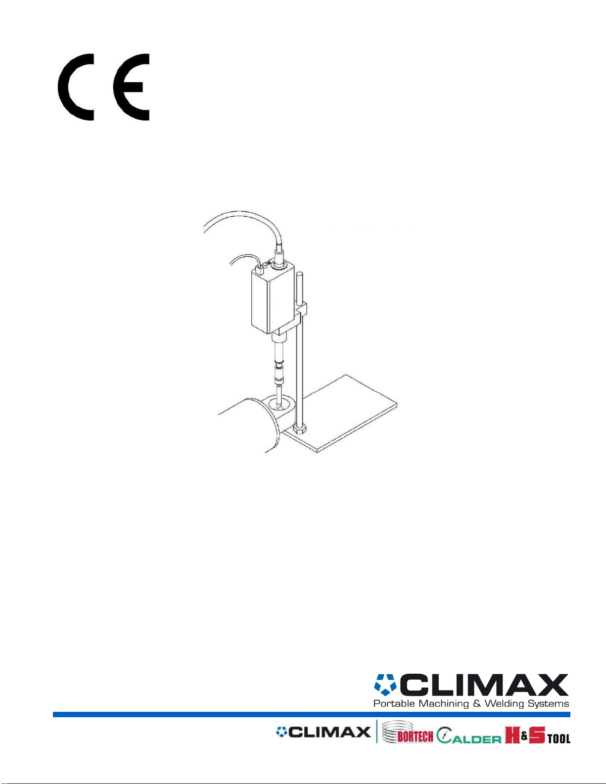
MAJOR ASSEMBLIES ........................................................................................................................................................................14
OPTIONAL EQUIPMENT ...................................................................................................................................................................15
ADJUSTABLE BASE ....................................................................................................................................................................................15
RADIAL MOUNT....................................................................................................................................................................................... 15
EXTENSION .............................................................................................................................................................................................15
TRAMMEL TORCH..................................................................................................................................................................................... 15
HEADLESS SUPPORT KIT.............................................................................................................................................................................15
BEARING CLEARANCE TORCH...................................................................................................................................................................... 15
QUICK SET-UP PROCEDURE .............................................................................................................................................................16
USING .035" WIRE................................................................................................................................................................................... 17
SETTING ROTATION SPEED .................................................................................................................................................................. 18
OPERATION .....................................................................................................................................................................................19
USE OF ACCESSORIES.......................................................................................................................................................................21
Use as follows:................................................................................................................................................................................22
MAINTENANCE ................................................................................................................................................................................23
REPLACING LINERS ................................................................................................................................................................................... 23
OPERATOR TRAINING ......................................................................................................................................................................24
WELDING POINTERS ........................................................................................................................................................................25
WIRE AND GAS........................................................................................................................................................................................25
WIRE FLIP............................................................................................................................................................................................... 25
VOLTAGE................................................................................................................................................................................................ 25
SPINDLE FEED AND WIRE LOCATION ............................................................................................................................................................ 25
WELDING IN THE HORIZONTAL AXIS.............................................................................................................................................................26
WELDING PROBLEMS AND TROUBLESHOOTING ..............................................................................................................................28

Page ii BW1000 Operating Manual
LACK OF FUSION TO THE BORE SURFACE ........................................................................................................................................................ 28
WIRE FEEDING STOPS AND WIRE BURNS BACK TO TIP .......................................................................................................................................28
WELD BEADS ARE "ROPY"..........................................................................................................................................................................28
TOO MUCH SPATTER ................................................................................................................................................................................ 28
POROSITY IN WELD: .................................................................................................................................................................................. 29
STEEL WELD DEPOSIT TOO HARD TO MACHINE ................................................................................................................................................29
WELD "GRAPING"WHEN WELDING IN THE HORIZONTAL AXIS: ........................................................................................................................... 30
BEAD ROPY,VOLTAGE HARD TO CONTROL,UNABLE TO CLEAR STUBBING:.............................................................................................................30
EXPLODED VIEW DRAWINGS AND PARTS LISTS ...............................................................................................................................31

P/N 40831, Rev. 4 Page 1
Labeling Guidelines
The purpose of product safety signs and labels is to increase the level of awareness to
possible dangers.
Safety Alert Symbols indicate DANGER, WARNING or CAUTION. These
symbols may be used in conjunction with other symbols or pictographs. Failure to
obey safety warnings can result in serious injury. Always follow safety
precautions to reduce the risk of hazards and serious injury.
DANGER
Indicates a hazardous situation that could be fatal or
cause serious injury.
WARNING
Indicates a potentially hazardous situation that
could be fatal or cause serious injury.
CAUTION
Indicates a potentially hazardous situation that
could result in minor to moderate injury, damage to
the machine or interruption of an important
process.
IMPORTANT
Provides critical information for the completion of a
task. There is no associated hazard to people or the
machine.
TIP
Provides important information regarding the
machine.

Page 2 BW1000 Operating Manual
Safety
Precautions and Rules for Safe Operation
•The BW1000 is designed for safety and ease of use. As with the operation of any
machinery, safety depends on the operator.
•It is most important that the operators read and understand the specific
instructions for set-up and operation of the BW1000 found in the operator's guide
as well as the following safety information.
•Only qualified individuals should attempt set-up, maintenance, and operation of
the BW1000.
•To assure that nothing gets caught in rotating BW1000 members, avoid wearing
loose fitting clothing and keep hair back or in a cap when operating the machine.
•Turn off the input power before changing torches or working on the machine.
•Read and follow all instructions for the power supply unit that you have chosen to
use with the BW1000.
Additional Welding Safety Precautions
•The operator and any personnel observing the machine when in use must use a
protective shield with a filter and cover plates which conform to ANSI Z87.1
standards.
•The operator needs protective clothing such as heavy shirts and cuffless pants of
a durable flame resistant material for protection from sparks and flame. Other
personnel in the area need to be protected from the arc rays by a screen and/or
a warning not to watch or otherwise expose themselves to the rays or to any hot
spatter.
•Practice "good housekeeping" in the area around the Borewelder. Keep
combustibles or any other fire hazards well away from the work area. For in-shop
use have a fire extinguisher readily available.
•Welding may produce gases and fumes that are dangerous to breathe. Sufficient
ventilation is needed to remove smoke while the machine is in use. The operator
should keep his head out of the fumes.
•Make the electrical installation in accordance with the National Electrical Code
and all local codes where applicable.
•Caution must be taken with regard to potentially dangerous electric shock. Do not
ever contact electrically live parts. Your hands can be insulated with dry, hole-
free leather gloves. When working in any damp areas or on metal floors, you
must insulate yourself from the ground and the work, making sure you have
complete protection if you are sitting or lying on the ground to operate the
machine.
To obtain additional details on safety precautions, we highly recommend "Safety
in Welding and Cutting", American National Standard ANSI Z49.1, which can be
purchased from the American Welding Society, Inc., 550 N.W. Lejeune Rd.,
Miami, Florida 33126. Their ordering number is 1-800-443-9353.

P/N 40831, Rev. 4 Page 3
Safety Precautions: General Hazards
The primary challenge for most on-site maintenance is that repairs are often done under difficult
conditions. Climax Portable Machining & Welding Systems leads the way in promoting the safe use of
portable machine tools. Safety is a joint effort. As the operator of this machine, you are expected to do
your part by scrutinizing the job site and closely following the operating procedures outlined in this
manual, your own company rules, and local regulations. Save all warnings and instructions for future
reference.
WARNING
Read all safety warnings and all instructions !
For maximum safety and performance, read and understand this entire manual and all
other related safety instructions before using this equipment. Failure to follow the
warnings, instructions and guidelines in this manual could cause personal injury, fatalities,
electric shock, fire and/or property damage.
QUALIFIED PERSONNEL
Before operating this machine, you must receive training specific to this machine from a qualified trainer. If you are
not familiar with the proper and safe operation, do not use the machine.
OBEY WARNING LABELS
Obey all warnings and warning labels. Failure to follow instructions or heed warnings could result in injury, or even be
fatal. Proper care is your responsibility. Contact Climax immediately for replacement of damaged or lost manuals or
safety decals. 1-800-333-8311
INTENDED USE
Only use the machine according to the instructions in this operating manual. Do not use this machine for any purpose
other than the intended use as described in this manual. When using tools, machine, accessories and/or tool bits, you
must determine the proper working conditions and the work to be performed.
STAY CLEAR OF MOVING PARTS
Keep clear of the machine during operation. Never lean toward or reach into the machine to remove chips or to adjust
the machine while it is running. Keep bystanders away while operating this machinery.
ROTATING MACHINERY
Rotating machinery can seriously injure an operator. Lock out all power sources before you interact with the machine.
KEEP YOUR WORK AREA CLEAN AND TIDY
Keep all cords and hoses away from moving parts during operation. Do not clutter the area around the machine.
Keep the work area clean and well lit.
AMBIENT LIGHTING
Do not operate this machine in ambient lighting that is less than normal intensity.
SECURE LOOSE CLOTHING AND LONG HAIR
Rotating machinery can seriously injure an operator as well as others close by. Don’t wear loose fitting clothing or
jewelry. Tie back long hair or wear a hat.
HAZARDOUS ENVIRONMENTS
Do not use the machine in a hazardous environment, such as near explosive chemicals, flammable liquids, gasses,
toxic fumes, or inappropriate radiation hazards.

Page 4 BW1000 Operating Manual
HOSES, PENDANT AND ELECTRICAL CABLES
Do not abuse cables. Never use the cord for carrying, pulling or unplugging. Remove any and all kinks before
straightening the cable. Keep cords and hoses away from heat, oil, sharp edges or moving parts. Plugs must match
the outlet. Never modify the plugs in any way. Do not use an adapter plug with grounded power tools. Do not expose
the machine to rain or wet conditions. Always examine hoses and cables for damage before use. Be cautious and
never drop electrical equipment, this will damage the components.
REPETITIVE MOTION
Individuals can be susceptible to disorders of the hands and arms when exposed to tasks that involve highly
repetitive motions and/or vibration.
STAY ALERT
Stay alert, watch what you are doing and use common sense when operating machinery. Do not operate
machinery while you are tired or under the influence of drugs, alcohol or medication.
Risk assessment and hazard mitigation
Machine Tools are specifically designed to perform precise material-removal operations.
Stationary Machine Tools include lathes and milling machines and are typically found in
a machine shop. They are mounted in a fixed location during operation and are
considered to be a complete, self-contained machine. Stationary Machine Tools achieve
the rigidity needed to accomplish material-removal operations from the structure that is
an integral part of the machine tool.
In contrast, Portable Machine Tools are designed for on-site machining applications.
They typically attach directly to the workpiece itself, or to an adjacent structure, and
achieve their rigidity from the structure to which it is attached. The design intent is that
the Portable Machine Tool and the structure attached to it become one complete
machine during the material-removal process.
To achieve the intended results and to promote safety, the operator must understand
and follow the design intent, set-up, and operation practices that are unique to Portable
Machine Tools.
The operator must perform an overall review and on-site risk assessment of the
intended application. Due to the unique nature of portable machining applications,
identifying one or more hazards that must be addressed is typical.
When performing the on-site risk assessment, it is important to consider the Portable
Machine Tool and the workpiece as a whole.

P/N 40831, Rev. 4 Page 5
Risk assessment checklist
Use these checklists as part of your on-site risk assessment and include any additional
considerations that may pertain to your specific application.
TABLE 1. RISK ASSESSMENT CHECKLIST BEFORE SET-UP
Before Set-up
I took note of all the warning labels on the machine.
I removed or mitigated all identified risks (such as tripping, cutting, crushing,
entanglement, shearing, or falling objects).
I considered the need for personnel safety guarding and installed any
necessary guards.
I read the Machine Assembly instructions and took inventory of all the items
required but not supplied.
I created a lift plan, including identifying the proper rigging, for each of the
setup lifts required during the setup of the support structure and machine.
I located the fall paths involved in lifting and rigging operations. I have taken
precautions to keep workers away from the identified fall path.
I considered how this machine operates and the best placement for the
controls, cabling, and the operator.
I evaluated and mitigated any other potential risks specific to my work area.
TABLE 2. RISK ASSESSMENT CHECKLIST AFTER SET-UP
After Set-up
I checked that the machine is safely installed and the potential fall path is
clear. If the machine is elevated, I checked that the machine is safeguarded
against falling.
I identified all possible pinch points, such as those caused by rotating parts,
and informed the affected personnel.
I planned for containment of any chips or swarf produced by the machine.
I followed the Maintenance Intervals with the recommended lubricants.
I checked that all affected personnel have the recommended personal
protective equipment, as well as any equipment required by the site or other
regulations.
I checked that all affected personnel understand the danger zone and are
clear of it.
I evaluated and mitigated any other potential risks specific to my work area.

Page 6 BW1000 Operating Manual
Limited Warranty
CLIMAX Portable Machine Tools, Inc. (hereafter referred to as “CLIMAX”) warrants that
all new machines are free from defects in materials and workmanship. This warranty is
available to the original purchaser for a period of one year after delivery. If the original
purchaser finds any defect in materials or workmanship within the warranty period, the
original purchaser should contact its factory representative and return the entire
machine, shipping prepaid, to the factory. CLIMAX will, at its option, either repair or
replace the defective machine at no charge and will return the machine with shipping
prepaid.
CLIMAX warrants that all parts are free from defects in materials and workmanship, and
that all labor has been performed properly. This warranty is available to the customer
purchasing parts or labor for a period of 90 days after delivery of the part or repaired
machine or 180 days on used machines and components. If the customer purchasing
parts or labor finds any defect in materials or workmanship within the warranty period,
the purchaser should contact its factory representative and return the part or repaired
machine, shipping pre- paid, to the factory. CLIMAX will, at its option, either repair or
replace the defective part and/ or correct any defect in the labor performed, both at no
charge, and return the part or repaired machine shipping prepaid.
These warranties do not apply to the following:
•Damage after the date of shipment not caused by defects in materials or
workmanship
•Damage caused by improper or inadequate machine maintenance
•Damage caused by unauthorized machine modification or repair
•Damage caused by machine abuse
•Damage caused by using the machine beyond its rated capacity
All other warranties, express or implied, including without limitation the warranties of
merchantability and fitness for a particular purpose are disclaimed and excluded.
Terms of sale
Be sure to review the terms of sale which appear on the reverse side of your invoice.
These terms control and limit your rights with respect to the goods purchased from
CLIMAX.
About this manual
CLIMAX provides the contents of this manual in good faith as a guideline to the
operator. CLIMAX cannot guarantee that the information contained in this manual is
correct for applications other than the application described in this manual. Product
specifications are subject to change without notice.

P/N 40831, Rev. 4 Page 7
Bortech Limited Warranty
Bortech warrants new equipment, not classified as expendable, against defects in workmanship and
material for one year of normal use from the date of receipt by the end user. The following conditions
shall be met in order for this warranty to be enforced:
•Equipment has been stored in accordance with Bortech's instructions.
•Equipment has been operated in accordance with Bortech's instructions.
•Equipment has been maintained in accordance with Bortech's instructions.
•Equipment has not been partially or completely disassembled, or otherwise tampered with -
without proper written authorization.
•Equipment is owned by the original purchaser
It shall be the warrantee's responsibility to prove compliance with the above conditions of warranty
enforcement. Bortech has the option to repair or replace any components or parts of the BW1000 that are
determined by Bortech to be defective.
Goods returned are done so at the customers risk and expense, including all transportation and
packaging costs. The liability of Bortech Corporation with respect to supplying said equipment or its use
by the Buyer, shall not exceed the cost of correcting defects in the equipment or replacing defective parts.
When the period of warranty expires, all such liability shall terminate.
Expendable items referred to above, include, but are not limited to torches number 00 and 0, and all tips,
nozzles, diffusers, and liners.

Page 8 BW1000 Operating Manual
CE Data
DECLARATION OF CONFORMITY
Issued by: Climax Portable Machining and Welding Systems
Date of Issue: (Original Dated)
Type of Equipment: Automated Bore Welding Equipment
Brand Name: Climax Portable Machining and Welding Systems BoreWelder
Model Number: BW1000
Serial Numbers: (See Machine)
Audible Noise Levels:
➢Surface sound pressure level (in dBA) 70 dBA
➢Sound power level (in dBA) 84 dBA
➢Sound pressure level for operator (80 dBA) and bystander (75 dBA)
Please note that this information is provided as a guide and you, or your manufacturer,
are cautioned that specific requirements are contained within each directive.

P/N 40831, Rev. 4 Page 9

Page 10 BW1000 Operating Manual
Safety
In accordance with CE standards
•Crushing risk exists if clamps are not tightened.
•Modification of safety features may result in operator or bystander harm.
•Do not integrate with faulty or poorly maintained equipment.
•Modification of thermal safety features may result in operator or bystander
harm.
•Modification of noise safety features may result in operator or bystander
harm.
•Modification of vibration safety features may result in operator or
bystander harm.
•Grease and/or oil native to machinery may result in allergic reaction to
operator.
•Smoke from welding metals may be harmful if inhaled.
•Gas bottle needs to be closed when not in use and ventilation always
adequate.
•Modification of ergonomic safety features may result in operator or
bystander harm.
•Dust from grinding wheel may be inhaled or get into eyes.
•Dust, dirt, and/or sand may cause machine to cease, posing risk to
operator.
•Grease and/or oil may cease in cold weather, posing risk to operator.
•Do not operate with substance outside of specifications.
•Do not operate without proper ear protection.

P/N 40831, Rev. 4 Page 11
Operation
The BW1000 is an automated welding device that uses a rotating and helically retracting
spindle/torch, which must be coupled with a MIG Wire-feeder to deposit Weld on the surface of
a bore or pin. The rate of axial feed per revolution is fixed. Torch selection, and/or adjustments
to the swivel head accommodate differences in bore diameter.
During set-up, the operator is required to:
•Align the Borewelder to the bore, (using either the appropriate interface
tooling for Boring bar to be used, or the Bortech Adjustable base).
•Determine the proper torch/bore clearance, and to set the initial Rotation
speed and Wire speed and Voltage settings.
•Start the BW1000 spindle rotation, and the Wirefeeder / Power supply in
use.
•Remain in visual contact with the welding process, and make adjustments
necessary to wire speed, voltage and rotation speed to maintain good
weld quality.
•Stop the BW1000 spindle rotation, and Wirefeeder / Power supply in use.

Page 12 BW1000 Operating Manual
Specifications
Welding Process - Metal-Inert-gas (MIG).
Wire Diameter Range - .030 - .045 inch (.8 - 1.2 mm)
Unsupported Torch Reach - 39 inches (990.6 mm)
Stroke Length - 9 inches
Feed thread - 8 TPI or .125” per revolution
Maximum Continuous Welding Current –140 amps
Welding Power Required. - Constant Voltage (CV)
BW1000 Power - 220v 50/60Hz VAC (120v model also available)
Contactor Control - Provided via remote switch
Typical Voltage Operating Range (short arc/. 035 wire) 16 to 17.5 volts
Component Weight - 17 lbs.
Buildup Diameter Ranges
BW1000 buildup diameter ranges;
@ 20 IPM .88 to 24 inches
#00 Torch .88in –1.8in (29063)
#0 Torch 1.80in - 3.0in (28448)
Head # 1 Swivel 2.7in –8.2in (39725)
Head # 2 Swivel 8.0in –12.0in (39726)

P/N 40831, Rev. 4 Page 13
Power Supply Compatibility
The BW1000 works well with numerous wire-feeders. It is imperative however that a Constant
Voltage MIG Process is utilized.
Power supplies with a rating of 175 amps are sufficient for the BW1000. The power supply must
be of the constant voltage (CV) type (suitable for MIG welding).
Only licensed electricians should perform attachment of the power supply control cable (trigger
or contactor control) to the wire-feeder. This should be done only after a thorough appreciation
of the theory of operation of the wire-feeder/power supply has been gained by studying this
manual and appropriate power supply information.
WARNING
Improper connections may result in dangerous electrical shock!
Damage to the power supply or wire-feeder is possible.

Page 14 BW1000 Operating Manual
Major Assemblies
Borewelders are highly configurable with many options and accessories. This manual covers the use and
operation of all of those possible options. The machine configuration purchased by a customer may not
contain all of the options and accessories in this manual. If a specific machine application requires
additional options or accessories, please contact a Climax sales representative at 1-800-333-8311 for
assistance in obtaining the needed components.
The BW1000 provides the circular and axial motion required to accomplish bore build up. It also provides
for the passage of weld current, welding wire, and shielding gas to the welding torch. BW1000 rotational
speed and direction is controlled at the rear face of the machine.
BW1000
Provides the circular and axial motion required to accomplish bore build up. It also provides for the
passage of weld current, welding wire, and shielding gas to the welding torch. BW1000 rotation
speed is controlled at the rear face of the machine.
Conduit Assembly
Provides passage of welding current, welding wire, and shielding gas to the BW1000. Includes
Wire feed Control Cable for actuation of trigger circuit contactor.
Swivel Head Assembly
(35603) Designed for use with multiple torch heads, this ball-and-seat device incorporates a
conductive path and gas seal for weld current while providing a fine diameter adjustment for
torches (39725) and (39726). Angle changes of the 7/16–20 stem of up to 10 degrees off-center
can be accommodated.
Torch Assemblies
(39725 and 39726) Sized for welding holes from 2.7” to 12 inches in diameter when used in
conjunction with the swivel head. In addition, Standard Torch Adapter (36170) is for use of #00
torch (29063) and #0 torch (28448) enabling bore-welding range capability down to .875”
diameter.
Extension Assemblies
Facilitate remote placement of Swivel head and torches for extended reach.
(29038) 3 inch, (29039) 6 inch, (29040) 12 inch.
Headless Support Kit Assembly
(40877) Supports extensions when rigidity in setup is needed (greater than 40” reach).
Mounting rod
(30773) to mount the BW1000 to adjustable base or Boring Bar interface.
Carrying Case
For protection and storage of your Borewelder.

P/N 40831, Rev. 4 Page 15
Optional Equipment
Adjustable Base
(29037) provides support for the BW1000 while allowing leveling and centering adjustment. This
is generally required when a boring bar interface is not available. This is a nonmagnetic base for
safe attachment and can be leveled on a variety of uneven surfaces.
Radial Mount
(40958) This part was designed for use between the mounting rod and the borewelder,
extending the distance between them to 3.98”. This mount is the correct distance for most
Boring bar interfaces that designed for the CLIMAX BW3000. The BW1000 is a center mount
system enabling Climax Boring Bars to interface kits more effectively than previous designs.
The radial mount resolves the issue of a newly design machine interfacing with an old
environment, while making possible the use of the AUTO-BOREWELDER with adjustable base.
Extension
(29065) 18-inch extension
Trammel Torch
(27013) for buildup of outside diameters up to 14” diameter at 10” long
Headless Support Kit
(40877) provides support of extensions when more rigidity in setup is desirable and when
extension reach is greater than 40” reach.
Bearing Clearance Torch
(63916) capable of welding 12 to 27 inch diameter bores

Page 16 BW1000 Operating Manual
Quick Set-Up Procedure
1. Connect remote trigger switch and Wire feed conduit to wirefeeder.
2. Attach Mounting rod to Boring Bar interface if applicable. (Or Adjustable
Base)
3. Install BW1000 in appropriate position onto Mounting Rod for coarse
alignment of spindle to bore axis. (If utilizing Adjustable base, See
“Detailed use of Adjustable base”.)
4. Connect Swivel Head and proper torch for the size bore to be welded.
(See Use of Swivel Head for details on this part.)
5. Rotate Feed Knob to move spindle to the extended position
6. Slide the BW1000 along the Mounting Rod to bring the torch end to the
bore end.
7. Lock the Radial Mount to the Mounting Rod
8. Retract the machine to the top of the Bore
9. Connect the power cord to the end of the BW1000.
10.To center the machine, check the adjustable axes by using the Torch
nozzle as an indicator, and rotating the torch, referencing the bore
surface. Only one axis is adjustable with the Boring Bar interface; i.e. the
“swing” axis from mounting rod.
11.Set the torch nozzle to bore clearance from 1/8 to 1/4 inch.
12.Connect BW1000 end of Wirefeeder Conduit to the Brass Power Coupling
and secure setscrew.
13.Without weld power hooked to wirefeeder, push the Trigger switch and
feed wire through the conduit of the BW1000. If there are issues feeding
wire through the torches, try straightening an 8 inch section of wire before
loading the wirefeeder to help the wire to pass through the system.
14.Set Rotation Speed to dial setting by use of the chart at the end of this
manual. Timing the spindle rotation for accuracy is good practice.
15.Extend spindle through bore again, by rotating the feed knob, and place
machine so that the wire will contact approximately 1/16 to 1/8 inches from
the edge of the bore.
16.Ensure that shielding gas, power supply and welding leads are properly
connected and ready for welding.
17.Ensure that the approximate voltage of your Power supply is not above 18
volts and set wirespeed to 250 IPM. (This is approximately 130 amperes
for .035 wire, or 4.2 lbs per hour.) In MIG welding, the wire speed bears a
direct relationship to the weld current.
Table of contents
Other Climax Welding System manuals