Climma CWS Setup guide

Installation, usage and
maintenance manual
CLIMMA CWS
DC INVERTER
Rev. 190124
Veco S Installation Manual –Page 2 / 20
Table of Contents
1. Introduction ................................................................................................................................................................................................................... 3
1.1. General information ......................................................................................................................................................................................... 3
1.2. System features ................................................................................................................................................................................................. 3
1.3. Installation .......................................................................................................................................................................................................... 3
1.4. Transport and handling .................................................................................................................................................................................. 4
1.5. Unpacking ........................................................................................................................................................................................................... 4
1.6. Directives ............................................................................................................................................................................................................. 4
1.7. General safety .................................................................................................................................................................................................... 4
2. Installation ...................................................................................................................................................................................................................... 5
2.1. Climma DC chiller positioning ...................................................................................................................................................................... 5
2.2. Electronic control box and display .............................................................................................................................................................. 5
2.3. Flow switch installation .................................................................................................................................................................................. 5
2.4. Grounding ........................................................................................................................................................................................................... 5
2.5. Chiller condensate ............................................................................................................................................................................................ 6
2.6. Other system components: fancoils ........................................................................................................................................................... 6
2.7. Other system components: sea water circuit ........................................................................................................................................... 6
2.8. Other system components: fresh water circuit ....................................................................................................................................... 7
2.9. Electrical connections ...................................................................................................................................................................................... 8
2.10. Installation checks ............................................................................................................................................................................................ 8
3. Operating instructions ................................................................................................................................................................................................ 9
3.1. The electrical control box ............................................................................................................................................................................... 9
3.2. The display .......................................................................................................................................................................................................... 9
3.3. Modes of operation .......................................................................................................................................................................................... 9
3.4. Climma functions ............................................................................................................................................................................................ 10
3.5. Starting the unit .............................................................................................................................................................................................. 10
3.6. Shut off procedure ......................................................................................................................................................................................... 11
3.7. Option Menu .................................................................................................................................................................................................... 11
3.7.1. User Menu ................................................................................................................................................................................................... 12
3.7.2. Input/Output .............................................................................................................................................................................................. 13
3.7.3. Language & Infos....................................................................................................................................................................................... 14
3.8. Warnings and errors ....................................................................................................................................................................................... 14
3.9. Mechanical remote control (optional) ..................................................................................................................................................... 15
3.10. Secondary digital display (optional) ......................................................................................................................................................... 15
4. Maintenance and cleaning ...................................................................................................................................................................................... 16
4.1. Basic maintenance .......................................................................................................................................................................................... 16
4.2. Extended maintenance ................................................................................................................................................................................. 16
4.3. Winterization ............................................................................................................................................ Error! Bookmark not defined.
5. Warnings, alarms and troubleshooting ............................................................................................................................................................... 17
5.1. Warnings and alarms ..................................................................................................................................................................................... 17
5.2. Basic troubleshooting ................................................................................................................................................................................... 20

Veco S Installation Manual –Page 3 / 20
1. Introduction
1.1. General information
Thank you for purchasing a Climma CWS system!
This manual will provide necessary information for the proper installation, operation, and maintenance of
your Climma system.
Climma chiller and products are designed and produced to the highest standards and they are all tested
in the factory. If your Climma system is used according to the guidelines in this manual, it will guarantee
you trouble free operation for many years.
If you require assistance, please contact one of our many authorized service centers. To find the service
center please check our website www.veco.net or write us at customerser[email protected].
WARNING
This unit should only be used for the purposes for which it was designed. The manufacturer declines all
responsibility for any damage caused by incorrect or unreasonable use, such as:
improper use by untrained persons;
technical modifications or operations not suited to specific models;
use of non-original or non-specific spare parts;
1.2. System features
Following the main features of the Climma DC chillers:
Variable Output from a Single Air-conditioning Unit. Depending on the heat load requirements,
the compressor frequency varies controlling the output capacity, to produce faster cooling and
heating, significantly improving the comfort on-board.
Water Cooled Inverter Compressor. Climma’s water cooled inverter protects the DC brushless
compressor from excessive temperature, current overload and irregular voltage supply, allowing it
to be installed in the engine room without additional ventilation. Added to this, the electronic
control provides continuous monitoring of the compressor curve to keep the unit within safe
operating limits, eliminating also stop-start cycles.
Eco mode. This function has been specifically developed to optimize the power consumption of
the system in three principle ways: it enables the chiller to work more efficiently with a smaller
output generator than would ideally be required; in ECO mode the power consumption is further
reduced during night operation when only a courtesy/night generator is working running and less
power is needed; ECO mode allows the air-conditioning to run while on the dock with a limited
shore power supply.
No Start Load. By using a DC compressor with inverter the Climma compressor starts at a low
frequency requiring a fraction of the power.
Up to 50% energy saving
A Climma centralized air-conditioning system includes different products: the Climma DC chiller, fancoils
installed in each cabins, fresh water piping that connects the chiller to the fancoils, sea water piping
bringing sea water to the chiller condenser, the fresh and the sea water pumps.
While the Climma system is running in cool mode, the Climma DC chiller is cooling the fresh water that
circulates in the fresh water circuit to the fancoils; heat is removed from the cabins through fancoils,
blowing fresh air into the cabins.
While in heat mode (reverse cycle mode), the Climma DC chiller is heating the fancoil water circuit that
brings heated water to the fancoils, allowing them to blow heated air in the cabins.
1.3. Installation

Veco S Installation Manual –Page 4 / 20
The unit must be installed by an authorized Climma service center and in compliance with the instructions
given in this manual.
1.4. Transport and handling
When loading or unloading the unit, use a fork lift equipped with forks at least 2/3 the length of the
shipping base.
Use an overhead lift if the unit is equipped with lifting eye-bolts.
Select lifting equipment suited to the weight and overall dimensions of the packaged unit or components.
Take every precaution to prevent damage, when handling the unit or components keeping in compliance
with the information given on the packaging material.
1.5. Unpacking
Remove all cardboard, wood or other materials from the wood base. Lift the unit or components by suitable
means (e.g. lift truck), remove the wood base, then set the unit or components into position.
Once all packing material has been removed, check that the unit has not been damaged in any way.
Caution: Wear protective gloves when handling any packing materials and the wood base. Dispose of all
packaging materials appropriately in accordance to local codes.
1.6. Directives
Climma DC chillers respect the following directives.
CE
Low voltage: 2006/95/EC
Electromagnetic Compatibility: 2004/108/EC
Machinery Directive: 2006/42/CE
Veco manufacturing Quality Standards UNI EN ISO 9001:2008
1.7. General safety
Injuries or accidents caused by failure to comply with the recommendations of this manual are solely the
responsibility of the unit operator.
Basic Rules for Safe Operation:
do not touch the unit with moist or wet hands or feet;
never operate the unit while barefoot;
before installation and maintenance operations, disconnect the unit from the power supply. failure
to comply may result in injury or death;
installation and maintenance of this system can be hazardous due to system working pressure and
electrical components. Only a Climma certified service center should install and maintain the
system;
to minimize the hazard of electrical shock and personal injury, this component must be effectively
grounded;
during installation and maintenance follow safety codes, wear safety glasses and work gloves;
Veco S Installation Manual –Page 5 / 20
2. Installation
WARNINGS
Failure to follow all the instructions in this manual can cause property damage, injury or death.
Improper installation, adjustment or alteration can cause property damage, injury or death.
Electrical connections should be performed only by a certified professional.
Electrical and grounding connections must comply with the National Electric Code and local
electric codes. Failure to comply with this procedure can cause property damage, injury or death.
Before connecting the unit to the electrical supply, verify that the electrical connection agrees with
the specifications on the data plate, placed on the main electrical box of the unit. Failure to comply
with this procedure can cause property damage, injury or death.
This appliance must be connected to a grounded, metal, permanent wiring system. Failure to
comply with this procedure can cause property damage, injury or death.
2.1. Climma DC chiller positioning
The Climma DC chiller must be installed in the engine room, technical space or similar area.
Normal engine room temperatures will not affect the Climma DC chiller, since the condenser and inverter
are water cooled. Climma DC chiller does not require additional ventilation during operation.
The unit must be accessible for service.
The unit must be secured on a surface using the mounting brackets below the drain pan.
WARNINGS
The Climma DC chiller is provided with an inverter mounted on the unit (VDF - Variable Frequency Drive).
The inverter is IP20, therefore the Climma DC chiller must be installed where it would not get wet.
2.2. Electronic control box and display
The electronic control box of the Climma DC chiller is already completely connected to the chiller.
The control box has to be installed close enough to the chiller, due to the connection to the unit, and to a
flat horizontal or vertical surface.
The control box has to be installed in a location free from water, water spray and moisture and it has to be
accessible for operation and maintenance.
The standard version has the display on the control box itself, but the display can be also remote.
If the display is remote, the distance between the control box and the display has to be:
50 meters with standard cable
500 meters with AWG22 twisted pair cable. Note: please contact Veco if you plan to install the
display at a distance exceeding 50mt.
2.3. Flow switch installation
Flow switch has to be connected to the electronic control box and it needs to be installed in the fancoil
water circulation system.
Please refer to instruction C897 for the correct installation.
WARNING: Failure to properly install the flow switch will void the warranty on the Climma DC chiller.
2.4. Grounding
The Climma DC chiller has to be properly grounded to prevent corrosion due to stray current.
WARNING: Failure to properly ground the Climma DC chiller will void warranty.

Veco S Installation Manual –Page 6 / 20
2.5. Chiller condensate
Every Climma DC chiller has two drains for condensate water.
At least one drain has to be properly connected to ensure the correct condensate water drainage.
Plastic condensate drain nipples are provided in a separate plastic bag to help the installation.
2.6. Other system components: fancoils
Climma fancoils have to be installed in a technical space inside or close to the cabin they have to cool/heat.
Fancoils need to be properly secured on a leveled surface in order to operate correctly and remove the
condensation. Return air flow from the fancoil has to be ensured as well as the supply air flow from the
fancoil.
WARNING
No fancoil has to be installed close to engine room area and it must be ensured that no vapor or air from
the engine room can enter in the return air flow of the fancoil.
The positioning of the fancoil display is important. The temperature sensor is mounted on the display,
therefore the display has to be mounted on an inside wall, around the mid-height of the cabin where the
air can circulate so that it can sense the correct temperature.
If a correct positioning is not possible, a remote temperature sensor can be mounted; in this case, the
sensor must be placed behind the return air grill. In this case, the display temperature sensor will be
automatically excluded.
WARNING
Do not place the temperature sensor on the supply air flow or close to return/supply grills, under the
sunlight or close to heating devices.
Ducting of the return and supply air of the fancoil has to be done properly; ducts must be short and as
straight as possible, avoiding bends greater than 90° or loops.
Supply air ducting has to be at least 1.5 meter (5’) in order to reduce fan motor noise, but it should not
exceed 6 meters in order to reduce pressure drops.
Supply and return grills must be located not too close to each other, in order to avoid the supply air to
enter directly in the return air flow. Return grill should be placed below while supply grill should be placed
over the mid-height, as high as possible in the cabin.
WARNING
Failure to proper position the supply and return grills will cause no mixing between the cooler
temperatures and the warmer temperatures.
All Climma fancoils are provided with condensate drains to remove condensation produced by the fancoil;
condensation can reach 2 liters per hour, therefore condensate drains must be properly connected and
tested during installation. Drains should be as short and as downhill as possible, with no loops and bends.
To test it, pour some water in the fancoil pan and check that all water flows out of the pan through the
drains.
2.7. Other system components: sea water circuit
The Climma DC chillers have a water cooled condenser therefore they need to be connected to sea water
to operate correctly.
The sea water circuit includes: a sea water pump sized according to the chiller capacity, a sea water intake
and outlet and a sea water strainer.
The sea water in the circuit should not exceed 0.6 m3/h every 12.000 Btu/h (2,64 GPM or 10 lt/m per 1 TON)
of chiller capacity.
Veco S Installation Manual –Page 7 / 20
Chiller rated capacity is guaranteed at 20°C (68°F) sea water temperature; the system will work in cool mode
up to 40°C (104°F) and in cool mode with a sea water temperature up to 5°C (41°F).
The sea water circuit must always have an uphill incline from the sea water inlet to the chiller condenser to
prevent the system to run properly. All hoses should be installed as straight as possible with no loops and
bends.
All metal components of the sea water circuit must be properly grounded.
SEAWATERPUMP
The sea water pump has to be properly secured on a leveled surface in order to operate correctly; Use the
special fixing kit with anti-vibration supports.
The sea water pump has to be installed below the water line in order to operate correctly.
SEAWATERINTAKE
Sea water intake has to be installed as far below the water line to ensure always that no air enters the sea
water circuit.
SEAWATERSTRAINER
Sea water strainer has to be installed between the sea water intake and the sea water pump and it must be
accessible for cleaning operations. The strainer has to be cleaned periodically.
WARNING: Sea water strainer is mandatory in the seawater circuit. Failure to install the sea water strainer
will void the warranty.
SEAWATEROUTLET
The sea water outlet has to be installed above the sea water line, but as close as possible to it to reduce
noises.
2.8. Other system components: fresh water circuit
The fresh water circuit is a closed loop bringing water from the chiller to the fancoils and then back to the
chiller again. The circuit has the following components: a fresh water pump, flow switch, manifolds, hoses,
an expansion tank and an air-bleeder; everything is sized accordingly to the fancoils number, type and
overall capacity.
Water pressure in the circuit must be between 1 and 1.5 Bar (14.5 and 22 psig).
FRESHWATERPUMP(CIRCULATIONPUMP)
The fresh water pump must be installed near the Climma DC chiller. The pump has to be installed on the
return line of the fresh water circuit, pumping water directly in the chiller and then to the fancoils.
FLOWSWITCH
Flow meter has to be installed on the fresh water circuit and it has to be accessible for maintenance.
The flow meter switch is mandatory safety equipment that will stop the system whenever the fresh water
flow stops or if it is not enough.
The flow meter switch has to be connected to the main electrical box of the unit as specified in the electrical
schematic.
Make sure that the flow meter is correctly connected to the control box. To test it, simulate a low flow
situation pressing the lever inside the cover of the switch.
MANIFOLDS
Manifolds should be installed to be accessible for maintenance. If calibrating valves are installed, they have
to be completely opened.
HOSES
The water circuit must be as simple and straight as possible, avoiding bends, loops.
Veco S Installation Manual –Page 8 / 20
EXPANSIONTANK
The expansion tank allows the water in the system to expand as it gets hot when the chiller is in heat mode
and it also acts as a cushion. The expansion tank has to be installed in the fresh water pump inlet.
AIRBLEEDER
The automatic air bleeder must be installed on the pump outlet. This will prevent that any air in the circuit
reaches the fan coils and all the legs of the circuit.
ANTIFREEZESOLUTION
The fresh water circuit needs to be filled with water (80%) and antifreeze (20%). Antifreeze will prevent
water and pipes from freezing. Antifreeze also reduces the corrosion inside the fresh water circuit.
Always check that the pressure gauge shows 1.5 Bar in the fresh water circuit.
We suggest two methods for filling the fresh water circuit with antifreeze:
Calculate approximately the circuit capacity; Fill the circuit with water and add to it 20% of
antifreeze, using the second charging valve by gravity or using a pressure pump. Then connect the
circuit to the sanitary water circuit of the vessel, pressurize up to 1.5 Bar and start purging the air.
It is obvious that if purging will be difficult the percentage of antifreeze will decrease, as more water
will be needed to fill the circuit, therefore more antifreeze must be added to the circuit.
Empty the circuit from the water used for leak test. Prepare an antifreeze solution of the quantity
needed to fill the circuit, made with 20% of antifreeze liquid; fill the circuit using a pressure pump.
Then proceed with purging air and topping up the pressure using the solution.
2.9. Electrical connections
The unit must be installed on a dedicated circuit with a rated thermal-magnetic circuit breaker. The circuit
breaker and electric cables (power supply) must be rated for the unit and comply with all local and national
codes.
The manufacturer will not be held responsible for damage or injuries due to improper installation.
Incorrect installation will void the Manufacturer’s warranty.
The electrical control box is already connected by Veco; to install the electrical box:
Connect the power supply to the electrical box
Connect the sea water pump to the electrical box
Connect the circulation (fresh) water pump to the electrical box
Please refer to the Electrical schematics in this manual.
2.10. Installation checks
The following checks MUST be made during the initial field start-up:
Check all wire connections.
Check electrical input.
Check the standard pressure in the refrigerant system.
Check the expansion valve during operation.
Note: If the unit and/or remote condensing unit were not transported in an upright position, or has been
overturned during the installation process, allow them to stand, in an upright position, at least 4 hours
before starting the unit.
Veco S Installation Manual –Page 9 / 20
3. Operating instructions
The unit can be controlled by the main display on the electrical control box, by the remote mechanical
panel or remotely via Modbus protocol. In this chapter only the main electrical box control and remote
mechanical panel are shown.
3.1. The electrical control box
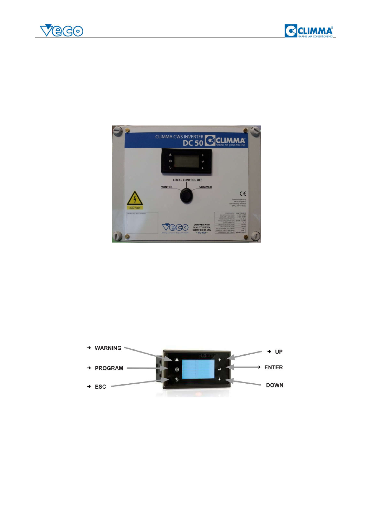
The electrical control box of the chiller Climma DC can be external, as in the DC35, DC50 and DC65, or
internal, as in the DC130.
Exampleofexternalelectricalbox.
The digital display can be mounted on the electrical box, on the unit iself, but it can also be remote.
The electrical box, or the unit in case of internal electrical box, has to be connected during the installation
to the main power supply, to the sea water pump and to the circulation pump.
The electrical box is already connected to: the inverter, the RC valve and water valve on the chiller, to the
electronic expansion valve, to the flow meter and to all the pressure and temperature sensors required by
the unit.
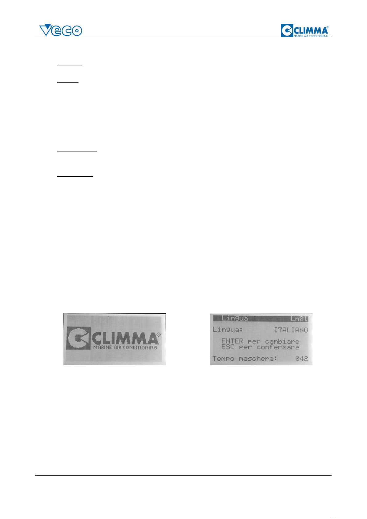
3.2. The display
The display has 6 buttons:
WARNING: this will allow to access in the Warning/Error screens
PROGRAM: this button allows to enter in the programming mode
ESC: this button allows to exit from the current screen and go back to the previous level
ENTER: when the cursor is on a value, the button allows to confirm the value
UP/DOWN: these buttons allows to move between values or screens
3.3. Modes of operation
Veco S Installation Manual –Page 10 / 20
The unit has 2 possible modes:
SUMMER: When the unit is in SUMMER mode, the system will run in cool mode as chiller, cooling
the water until a specified set-point temperature value is reached.
WINTER: When the unit is in HEAT mode, the system will run as heat pump, heating the water until
a specified set-point temperature value is reached.
When the system is powered up it will recall the previous mode of operation.
When the system starts for the first time, it will start in OFF status, with the default mode on.
3.4. Climma functions
When the unit is working, the system can run with two different functions:
AUTOfunction: when system is in AUTO function, the Climma Control will automatically adjust the
system power: when more power is requested, the compressor will run up to its maximum speed,
but when less power is requested, compressor will slow down.
ECOfunction: when system is in ECO function, the Climma Control will automatically adjust the
system power, but this time the maximum power is limited to a specific ECO value, which allows
you to set a maximum power consumption, lower than the maximum system power consumption.
Example.
Chiller maximum power consumption: 4,2kW
Generator: 10kW
When you are running the generator you can set the AUTO function on. If the system will run at full power,
it will still work with no problems, even at maximum speed.
When you are docked, you cannot run the generation and you have only 4kW from the harbor, then you
can set the ECO function on. This will allow the system to run up to 50% of its overall power, this means
that the power consumption will be limited around 2kW, allowing the system to run anyway.
3.5. Starting the unit
To start the unit, turn on the main power supply from the dedicated circuit breaker.
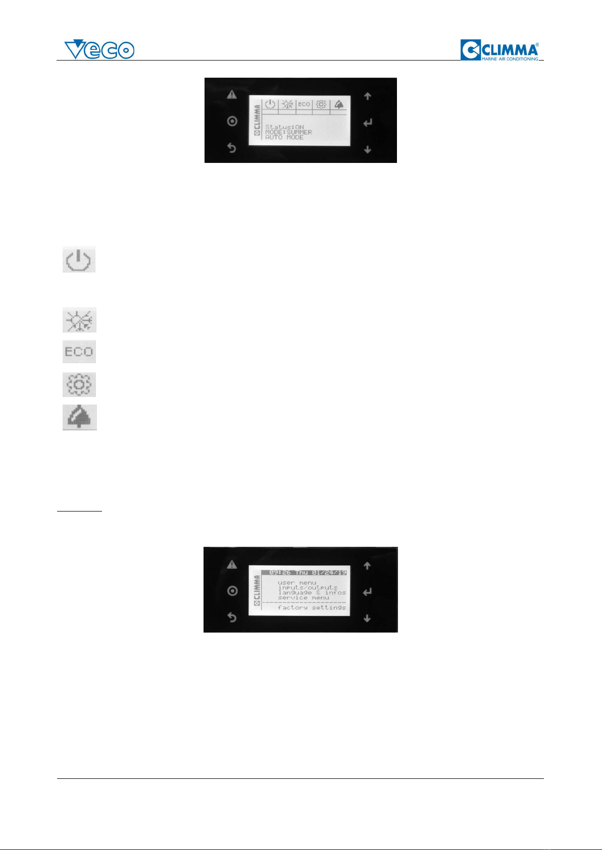
The display will show the following screens.
Screen 1. Screen 2.
When the display shows Screen 1, and later Screen 2, there is a short time where you can change the
language from Italian to English (or the other way around).
To change the language from the current one, press ENTER. To confirm the current language press ESC.
If nothing is pressed, the system will start with the current language settings.
After the language settings, the system will go to the main screen.
Veco S Installation Manual –Page 11 / 20
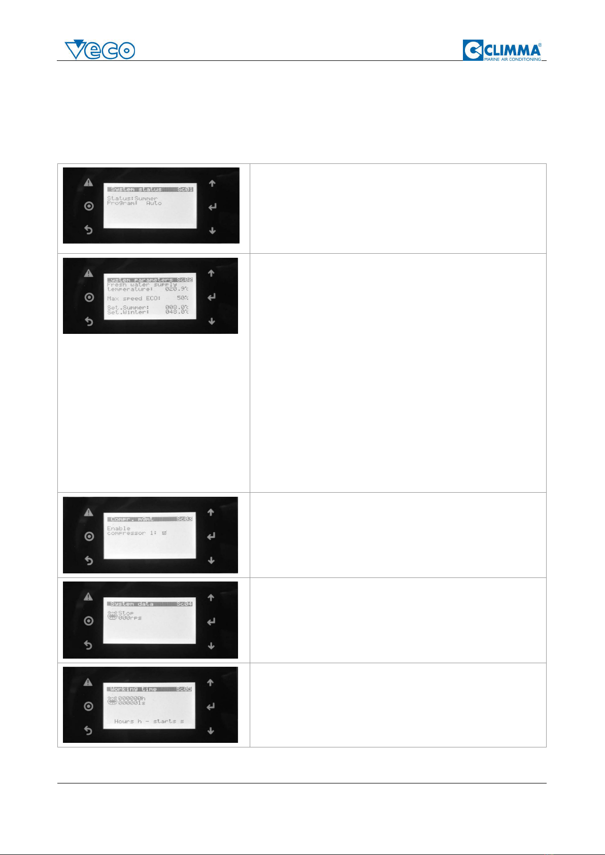
Mainscreen.
The main screen will show the current state of the system (Status: ON, OFF), the operation mode (Summer,
Winter) and the function active (Auto, Eco).
To turn on the system, press the DOWN/UP button to position the cursor on the ON/OFF symbol, then
press ENTER to change the Status and turn the system ON.
To turn off the system, press the DOWN/UP button to position the cursor on the ON/OFF symbol, then
press ENTER to change the Status and turn the system OFF.
To change the system Mode, press the DOWN/UP button to position the cursor on the Mode symbol,
then press ENTER to change the Mode from Winter to Summer, or the other way around.
To change the system Function, press the DOWN/UP button to position the cursor on the Function
symbol, then press ENTER to change the Function from Auto to ECO, or the other way around.
To access the Options Menu, press the DOWN/UP button to position the cursor on the Options Menu
symbol, then press ENTER to access.
To access the Alarm/Warning screens, press the DOWN/UP button to position the cursor on the Alarm
symbol, then press ENTER to access.
3.6. Shut off procedure
To stop the unit from running, first put the unit in OFF mode and then power off the system from the circuit
breaker.
WARNING Do not use the circuit breaker only.
3.7. Option Menu
Optionmenu.
From the main Option Menu, you can:
Access the UserMenu
Access the Input/outputs screens
Access the Language&Infos menu
Access the ServiceMenu (only for authorized service centers)
Access FactorySettings(only for authorized service centers)
To access one of these Options, select the Menu using the DOWN/UP button, then press ENTER.
To exit the screen and go back to the Main screen, press ESC.
Veco S Installation Manual –Page 12 / 20
3.7.1. User Menu
The main User Menu has a set of different screens, where you can check the system values, and change
some of them. To move between screens, use DOWN/UP buttons.
To go back to the main screen, press ESC.
SC01 screen shows system Status, Mode and Function.
Both the Status (Winter/Summer) and the Function (Auto/Eco) can
be changed.
To change them, press ENTER until the selector is on the value you
want to change (the value will blink), then use the arrows UP/DOWN
to modify the value. To confirm the value press ENTER again.
SC02 shows the fresh water supply temperature, the summer and
winter set-points values.
The set point values are the temperature set point for the unit when
running in cool/heat mode. The system will work to bring the
temperature of the return water to this value; when the value is
reached, the system usually stops.
The screen allows also to change the ECO Max Speed (default 50%);
this value is the maximum power in percentage that the unit can
reach when it is in ECO mode. It can be changed from 30% up to
70%.
In the following table, an estimate of the max power consumption is
shown for the most common ECO settings (DC50 model only).
ECO % RPS Consumption (A) Consumption (kW)
30 % 36 rps 4.9 A 1.0 kW
50 % 60 rps 8.8 A 1.9 kW
70 % 84 rps 14.7 A 3.3 kW
SC03 screen shows the list of compressors available in the system
and allows you to disable/enable each compressor.
To enable/disable compressors, press ENTER until the selector is on
the compressor (the value will blink), then use the arrows UP/DOWN
to modify the value. To confirm the value press ENTER again.
SC04 shows the list of compressors available and each compressor
speed in rps (if 0 then the compressor is off).
This is a read only screen, no value can be changed.
SC05 shows the list of compressors available and for each
compressor the running hours and seconds.
This is a read only screen, no value can be changed.
Veco S Installation Manual –Page 13 / 20
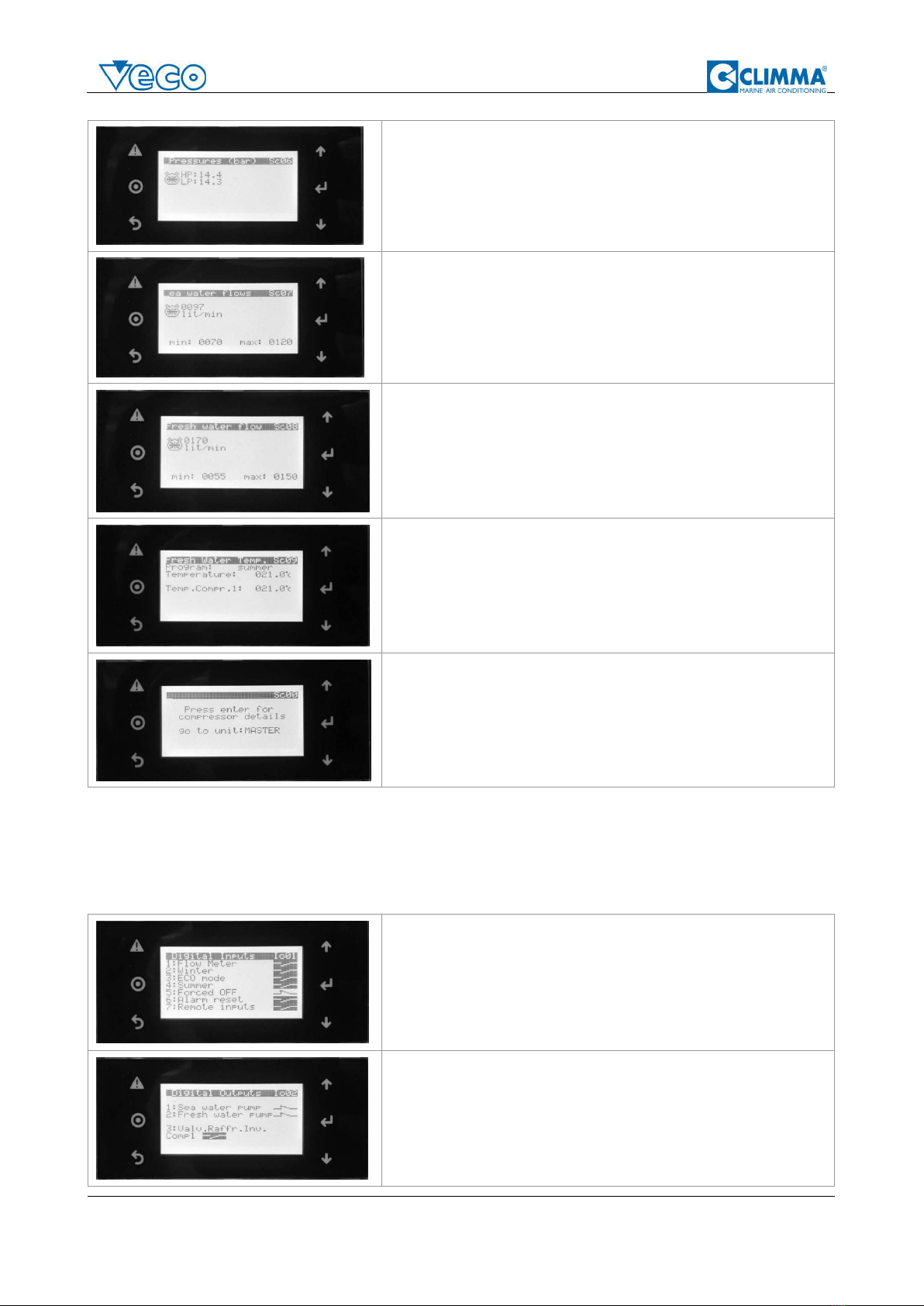
SC06 shows the list of compressors available and for each
compressor the high pressure value (discharge pressure) and low
pressure value (suction pressure).
This is a read only screen, no value can be changed.
SC07 shows the list of compressors available and for each
compressor the sea water flow value (in liters/minutes).
This is a read only screen, no value can be changed.
SC08 shows the list of compressors available and for each
compressor the fresh/circulation water flow value (in liters/minutes).
This is a read only screen, no value can be changed.
SC09 shows the Mode of the system, and the fresh/circulation water
temperature on the main Master compressor, and on the other
compressors in the system.
This is a read only screen, no value can be changed.
SC00 allows to access more details on each single compressor in the
system; a DC system can be made with 1,2, 3 or 4 compressor.
The first is always the Master unit, then you have Slave 1, Slave 2 and
Slave 3.
3.7.2. Input/Output
The Input/Output menu shows a set of different screens, where you can check the system input and output
values for troubleshooting. To move between screens, use DOWN/UP buttons.
To go back to the main screen, press ESC.
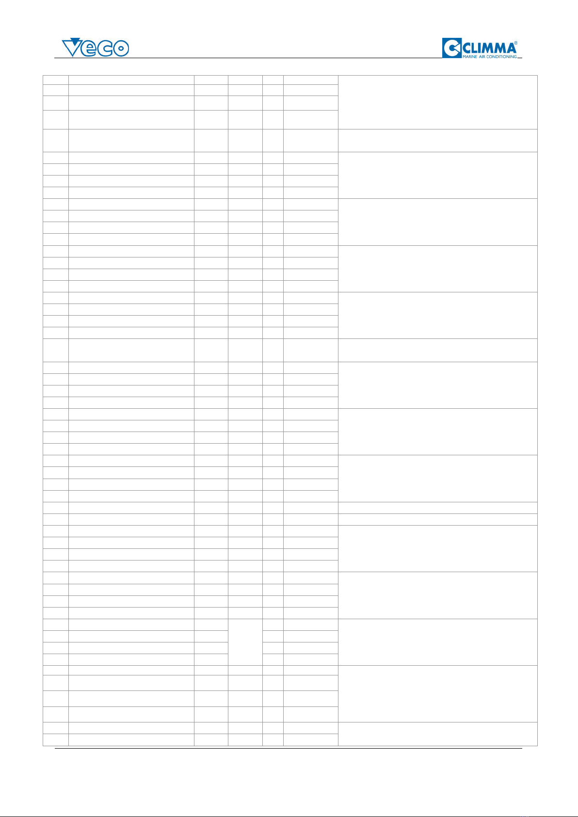
IO01 screen shows the different digital inputs to the board.
From this screen you can see if the input is “open” or “closed”.
This is a read only screen, no value can be changed.
IO02 screen shows the different digital outputs to the board, more
specifically the pumps and the inverter cooling valve.
From this screen you can see if the digital output contact is “open”
or “closed”.
This is a read only screen, no value can be changed.

Veco S Installation Manual –Page 14 / 20
IO03 screen shows the different digital outputs to the board, more
specifically, the reverse cycle valve and the system fan.
From this screen you can see if the digital output contact is “open”
or “closed”.
This is a read only screen, no value can be changed.
IO04 screen shows the different digital outputs to the board, more
specifically, if the electronic valve is in error status, and if there is a
general alarm.
From this screen you can see if the digital output contact is “open”
or “closed”.
This is a read only screen, no value can be changed.
3.7.3. Language & Infos
The Language & Infos menu shows a set of different screens where you can change basic system settings.
To move between screens, use DOWN/UP buttons.
To go back to the main screen, press ESC.
I01 screen shows the unit of measure, language and date & time
settings.
To change any of these values, press ENTER until the selector is on the
value you want to change (the value will blink), then use the arrows
UP/DOWN to modify the value. To confirm the value press ENTER
again.
I02 screen allows you to disable/enable language mask at startup, and
to change the show mask time. (default enabled - 30s)
To change any of these values, press ENTER until the selector is on the
value you want to change (the value will blink), then use the arrows
UP/DOWN to modify the value. To confirm the value press ENTER
again.
I03 screen shows the software and Bios version of your Climma DC
system.
While contacting a service center, please make sure to identify the
software version through this screen.
3.8. Warnings and errors
The system logs all alarms, warnings and errors, keeping track of all the information when the issue
occurred.
To access the Alarm/Warning screens, press the DOWN/UP button to position the cursor on the Alarm
symbol, then press ENTER to access.
When there is a warning/error, the main display will show a bell symbol; to see the warning/error details
you can:

Veco S Installation Manual –Page 15 / 20
- press the DOWN/UP button to position the cursor on the Alarm symbol, then press ENTER to access
- or press the WARNING button from the main screen
In order to navigate through the active warning and errors, use DOWN and UP buttons.
To go back to the main screen press ESC.
At the end of the active errors and warnings, or if no active alarm is there, you will see this screen:
Press ENTER to access the History Log of the previously warnings and errors of the system.
ExampleofActiveerror. ExampleofHistoryLog.
3.9. Mechanical remote control (optional)
Climma DC chillers allows you to add a simple mechanical remote panel to control the unit remotely.
The panel allows you:
- to turn the unit OFF, ON in Winter mode (HEAT) or ON in Summer mode (COOL)
- to enable or disable the ECO mode
- to see if there is any active error through the light (when the red light is on, an error/warning is
present in the system)
When the remote panel is connected, some functions are disabled from the main display. The main
display screen will look like this:
3.10. Secondary digital display (optional)
Climma DC chillers allows you to add a secondary digital display to the system. If the second display is
there, both displays will show you exactly the same thing at the same time.

Veco S Installation Manual –Page 16 / 20
4. Maintenance and cleaning
Climma DC chillers require some basic maintenance that has to be done frequently and some extended
maintenance to be done at longer intervals.
4.1. Basic maintenance
Following tasks need to be performed frequently.
Clean the seawater strainer to allow enough sea water to the condenser coil
The fresh water circuit has to be filled with water and no air must be present inside the circuit.
Pressure has to be between 1.5 Bar and 2 Bar (21 psi to 28 psi).
Fancoils return air filters have to be controlled, cleaned or changed regularly.
NOTE. It’s recommended that the system is regularly used. If the system is not used at least once a month,
then there can be problems with the pump seals or with the reverse cycle valve. Try to run the system at
least once a month, both in cool and in heat mode.
When the system is not run for a long period, it’s important to manually run the pumps, removing the back
cover and manually rotate the cooling fan inside the pump. This will extend the life of the rotating seal
which can remain stuck by salt and break at immediate start.
IMPORTANT: Be sure to correctly fix the back cover cap correctly before running the pump at the end of
the maintenance.
4.2. Extended maintenance
Following tasks need to be performed at a semi-annual.
Flush and clean the condenser with countercurrent hot water to prevent scale build-up in the coils
and obstructions. To do this, inlet and outlet connections have to be disconnected from the system.
Check the sea water pump (clean the pump according to the pump model instruction)
Check every sensor of the system to be properly connected to the control box and to be properly
installed on the system.
4.3. Anti-freeze solution
Periodically check that the anti-freeze solution in the fresh water circuit is always greater then 20% of the
overall circuit volume; this check has to be done periodically and always when there is a leak in the circuit.
When the boat is subject to a very cold climate, it may be necessary to increase the anti-freeze percentage
in the fresh water circuit, even when the system is not used.

Veco S Installation Manual –Page 17 / 20
5. Warnings, alarms and troubleshooting
5.1. Warnings and alarms
Code Description Reset Delay Alarm
relay
Action notes
AL1 Clock Board Fault compressor 1 Automatic Immediate
Yes Warning
There may be an issue with the battery in the board, please check the
battery and if it's not working change it.
Check also connections.
AL2 Clock Board Fault compressor 2 Automatic Immediate
Yes Warning
AL3 Clock Board Fault compressor 3 Automatic Immediate
Yes Warning
AL4 Clock Board Fault compressor 4 Automatic Immediate
Yes Warning
AL5 Extended memory fault compressor 1 Automatic Immediate
Yes Warning
Contact the closest Climma service center
AL6 Extended memory fault compressor 2 Automatic Immediate
Yes Warning
AL7 Extended memory fault compressor 3 Automatic Immediate
Yes Warning
AL8 Extended memory fault compressor 4 Automatic Immediate
Yes Warning
AL9 Max discharge pressure compressor 1 Manual Immediate
Yes OFF compressor Discharge pressure reading is more than the allowed value therefore
the systems shuts off to keep the compressor safe. Check the
pressure values registered in the log at the time of the error.
Check the sea water pump and flow, as there may be not enough
flow through the sea water condenser.
AL10 Max discharge pressure compressor 2 Manual Immediate
Yes OFF compressor
AL11 Max discharge pressure compressor 3 Manual Immediate
Yes OFF compressor
AL12 Max discharge pressure compressor 4 Manual Immediate
Yes OFF compressor
AL13 Min suction pressure compressor 1 Automatic Immediate
Yes OFF compressor
Suction pressure reading is below the safety levels. Please check the
value of the pressures and try to reset manually the alarm.
If it does not stop, contact the closest Climma service center.
AL14 Min suction pressure compressor 2 Automatic Immediate
Yes OFF compressor
AL15 Min suction pressure compressor 3 Automatic Immediate
Yes OFF compressor
AL16 Min suction pressure compressor 4 Automatic Immediate
Yes OFF compressor
AL17 Probe S1,S2,S3,S4 Alarms compressor 1 Manual 60sec Yes OFF compressor There is a problem with one or more probes. Please check the
probes connections. Try to reset manually the alarm, then if it does
not go away, shut off the system, wait 1 minute, then try to restart the
system. If the error does not go away, contact the closest Climma
service center.
AL18 Probe S1,S2,S3,S4 Alarms compressor 2 Manual 60sec Yes OFF compressor
AL19 Probe S1,S2,S3,S4 Alarms compressor 3 Manual 60sec Yes OFF compressor
AL20 Probe S1,S2,S3,S4 Alarms compressor 4 Manual 60sec Yes OFF compressor
AL21 Low superheat EVD compressor 1 Automatic Immediate
Yes Warning
Superheat value is below the threshold allowed, check and monitor
the system. Try to reset manually the alarm, then if it does not go
away, shut off the system, wait 1 minute, then try to restart the
system. If the error does not go away, contact the closest Climma
service center. If alarm is happening in heat mode, verify integral and
differential values if they are set to default.
AL22 Low superheat EVD compressor 2 Automatic Immediate
Yes Warning
AL23 Low superheat EVD compressor 3 Automatic Immediate
Yes Warning
AL24 Low superheat EVD compressor 4 Automatic Immediate
Yes Warning
AL25 Low evaporation temp. EVD compr.1 (LOP)
Automatic Immediate
Yes Warning The evaporating temperature of the system is low, maybe there is not
enough refrigerant or the probe is faulty. Try to reset manually the
alarm, then if it does not go away, shut off the system, wait 1 minute,
then try to restart the system. If the error does not go away, contact
the closest Climma service center.
AL26 Low evaporation temp. EVD compr.2 (LOP)
Automatic Immediate
Yes Warning
AL27 Low evaporation temp. EVD compr.3 (LOP)
Automatic Immediate
Yes Warning
AL28 Low evaporation temp. EVD compr.4 (LOP)
Automatic Immediate
Yes Warning
AL29 High evap. temp.EVD compr.1 (MOP) Automatic Immediate
Yes Warning The evaporating temperature of the system is too high, maybe the
probe is faulty. Try to reset manually the alarm, then if it does not go
away, shut off the system, wait 1 minute, then try to restart the
system. If the error does not go away, contact the closest Climma
service center.
AL30 High evap.temp.EVD compr.2 (MOP) Automatic Immediate
Yes Warning
AL31 High evap.temp.EVD compr. 3 (MOP) Automatic Immediate
Yes Warning
AL32 High evap. temp.EVD compr.4 (MOP) Automatic Immediate
Yes Warning
AL33 Low suction temp.EVD compressor 1 Automatic Immediate
Yes Warning The suction temperature value is too low, maybe there is not enough
refrigerant in the system and there's a leak, or maybe a probe is
faulty. Try to reset manually the alarm, then if it does not go away,
shut off the system, wait 1 minute, then try to res
tart the system. If the
error does not go away, contact the closest Climma service center.
AL34 Low suction temp.EVD compressor 2 Automatic Immediate
Yes Warning
AL35 Low suction temp.EVD compressor 3 Automatic Immediate
Yes Warning
AL36 Low suction temp. EVD compressor 4 Automatic Immediate
Yes Warning
AL37 Start failure compressor 1
After 5
manual
10 sec Yes Turn OFF An error occurred while starting compressor. Check sea water flow in
case compressor's envelope reaches zone 5 or zone 9. Then try to
reset manually the alarm, then if it does not go away, shut off the
system, wait 1 minute, then try to restart the system. If the error does
not go away, contact the closest Climma service center.
AL38 Start failure compressor 2 11 sec Yes Turn OFF
AL39 Start failure compressor 3 12 sec Yes Turn OFF
AL40
Start failure compressor 4
13 sec
Yes
Turn OFF
AL41 Envelope alarm compressor 1 Manual 60 sec Yes Turn OFF The compressor was working outside of its "safe" zone, therefore the
system stopped. Check sea water flow in case compressor's
envelope reaches zone 5 or zone 9. Then try to reset manually the
alarm, then if it does not go away, shut off the system, wait 1 minute,
then try to restart the system. If the error does not go away, contact
the closest Climma service center.
AL42 Envelope alarm compressor 2 Manual 60 sec Yes Turn OFF
AL43 Envelope alarm compressor 3 Manual 60 sec Yes Turn OFF
AL44 Envelope alarm compressor 4 Manual 60 sec Yes Turn OFF
AL45
Low pressure differential compressor 1
Manual
60 sec
Yes
Turn OFF
Delta Pressure < than minimum required for lubrication --> The
difference between the suction and discharge pressures is too low
and it can create problems to the compressor. Try to reset manually
the alarm, then if it does not go away, shut off the system, wait 1
minute, then try to restart the system. If the error does not go away,
contact the closest Climma service center.
AL46 Low pressure differential compressor 2 Manual 60 sec Yes Turn OFF
AL47 Low pressure differential compressor 3 Manual 60 sec Yes Turn OFF
AL48 Low pressure differential compressor 4 Manual 60 sec Yes Turn OFF
Veco S Installation Manual –Page 18 / 20
AL49
High discharge gas temperature compr. 1
Manual
Immediate
Yes
Turn OFF
Discharge max. Temperature --> The discharge temperature of the
system is too much and out of the allowed values. Check that there is
enough water going through the condenser.
Try to reset manually the alarm, then if it does not go away, shut off
the system, wait 1 minute, then try to restart the system. If the error
does not go away, contact the closest Climma service center.
AL50 High discharge gas temperature compr. 2 Manual Immediate
Yes Turn OFF
AL51 High discharge gas temperature compr. 3 Manual Immediate
Yes Turn OFF
AL52 High discharge gas temperature compr. 4 Manual Immediate
Yes Turn OFF
AL53 OLD - NOT USED ANYMORE
WAS: Temperature sensor B1 error Automatic 60 sec Yes Turn OFF OLD - NOT USED ANYMORE - WAS: Temp. Probe B1 (set-point)
faulty or disconnected
AL53_1
Flow probe B1 (fresh water) error compr.1 Automatic 60 sec Yes Turn OFF
Flow Probe B1 (fresh water) faulty or disconnected
- if available, check cabling and verify integrity of the sensor
- if not available, disable it from the emergency masks
AL53_2
Flow probe B1 (fresh water) error compr.2 Automatic 60 sec Yes Turn OFF
AL53_3
Flow probe B1 (fresh water) error compr.3 Automatic 60 sec Yes Turn OFF
AL53_4
Flow probe B1 (fresh water) error compr.4 Automatic 60 sec Yes Turn OFF
AL54 Temperature sensor B2 error compressor 1
Automatic 60 sec Yes Turn OFF
Temp. Probe B2 (set point and antifreeze) faulty or disconnected
AL55 Temperature sensor B2 error compressor 2
Automatic 60 sec Yes Turn OFF
AL56 Temperature sensor B2 error compressor 3
Automatic 60 sec Yes Turn OFF
AL57 Temperature sensor B2 error compressor 4
Automatic 60 sec Yes Turn OFF
AL58 Temperature sensor B3 error compressor 1
Automatic 60 sec Yes Turn OFF
Temp. Probe B3 (suction temperature) faulty or disconnected
AL59 Temperature sensor B3 error compressor 2
Automatic 60 sec Yes Turn OFF
AL60 Temperature sensor B3 error compressor 3
Automatic 60 sec Yes Turn OFF
AL61 Temperature sensor B3 error compressor 4
Automatic 60 sec Yes Turn OFF
AL62 Temperature sensor B4 error compressor 1
Automatic 60 sec Yes Turn OFF
Temp. Probe B4 (discharge temperature) faulty or disconnected
AL63 Temperature sensor B4 error compressor 2
Automatic 60 sec Yes Turn OFF
AL64 Temperature sensor B4 error compressor 3
Automatic 60 sec Yes Turn OFF
AL65 Temperature sensor B4 error compressor 4
Automatic 60 sec Yes Turn OFF
AL66 Temperature sensor B5 error compressor 1
Automatic 60 sec Yes Turn OFF OLD - NOT USED ANYMORE - WAS: Temp. Probe B5 (discharge
temperature) faulty or disconnected
AL53_1
Flow probe B5 (sea water) error compr.1 Automatic 60 sec Yes Turn OFF
Flow Probe B5 (sea water) faulty or disconnected
- if available, check cabling and verify integrity of the sensor
- if not available, disable it from the emergency masks
AL53_2
Flow probe B5 (sea water) error compr. 2 Automatic 60 sec Yes Turn OFF
AL53_3
Flow probe B5 (sea water) error compr.3 Automatic 60 sec Yes Turn OFF
AL53_4
Flow probe B5 (sea water) error compr.4 Automatic 60 sec Yes Turn OFF
AL67 Pressure sensor B6 error compressor 1 Automatic 60 sec Yes Turn OFF
Pressure Probe B6 (suction pressure) faulty or disconnected
AL68 Pressure sensor B6 error compressor 2 Automatic 60 sec Yes Turn OFF
AL69 Pressure sensor B6 error compressor 3 Automatic 60 sec Yes Turn OFF
AL70 Pressure sensor B6 error compressor 4 Automatic 60 sec Yes Turn OFF
AL71 Pressure sensor B7 error compressor 1 Automatic 60 sec Yes Turn OFF
Pressure Probe B7 (discharge pressure) faulty or disconnected
AL72 Pressure sensor B7 error compressor 2 Automatic 60 sec Yes Turn OFF
AL73 Pressure sensor B7 error compressor 3 Automatic 60 sec Yes Turn OFF
AL74 Pressure sensor B7 error compressor 4 Automatic 60 sec Yes Turn OFF
AL79 BMS offline heartbit Automatic
AL80 Inverter model not compatible Automatic Immediate
Yes Turn OFF
AL81 Compr.1 not started by excessive delta P Automatic 300 sec Yes Turn OFF
Start fail due to high DeltaP
AL82 Compr. 2 not started by excessive delta P Automatic 300 sec Yes Turn OFF
AL83 Compr. 3 not started by excessive delta P Automatic 300 sec Yes Turn OFF
AL84 Compr.4 not started by excessive delta P Automatic 300 sec Yes Turn OFF
AL85 Antifreeze alarm compressor 1 Manual Immediate
Yes Turn OFF
Anti-freeze temp.probe out of allowed range. If happening in cool
mode, verify integral and differential values if they are set to default.
Verify fresh water flow if available.
AL86 Antifreeze alarm compressor 2 Manual Immediate
Yes Turn OFF
AL87 Antifreeze alarm compressor 3 Manual Immediate
Yes Turn OFF
AL88 Antifreeze alarm compressor 4 Manual Immediate
Yes Turn OFF
AL89 Flow switch compressor 1 Manual
Startup
delay (15
sec)
Yes Turn OFF
Flow switch error. Low fresh water in the circulation circuit. Check
fresh water circulation.
AL90 Flow switch compressor 2 Manual Yes Turn OFF
AL91 Flow switch compressor 3 Manual Yes Turn OFF
AL92 Flow switch compressor 4 Manual Yes Turn OFF
AL93
Power+ offline compressor 1
Automatic
30 sec
Yes
Turn OFF
Inverter is offline, shut off the power supply and check the wiring
diagram and connections, then try to restart the system and reset the
alarm.
If the error does not go away, contact the closest Climma service
center.
AL94 Power+ offline compressor 2 Automatic 30 sec Yes Turn OFF
AL95 Power+ offline compressor 3 Automatic 30 sec Yes Turn OFF
AL96 Power+ offline compressor 4 Automatic 30 sec Yes Turn OFF
AL97 Alarms Power+ compressor 1 Manual Immediate
Yes Turn OFF See below detailed alarms/errors
AL98 Alarms Power+ compressor 2 Manual Immediate
Yes Turn OFF

Veco S Installation Manual –Page 19 / 20
AL99 Alarms Power+ compressor 3 Manual Immediate
Yes Turn OFF
AL100 Alarms Power+ compressor 4 Manual Immediate
Yes Turn OFF
AL101 Alarms board slave 1 offline Automatic 60 sec Yes OFF slave 1
Slave units offline. Verify BUS connections AL102 Alarms board slave 2 offline Automatic 60 sec Yes OFF slave 2
AL103 Alarms board slave 3 offline Automatic 60 sec Yes OFF slave 3
AL104 Alarms presence on unit slave 1 Immediate
No
Slave units with alarms AL105 Alarms presence on unit slave 2 Immediate
No
AL106 Alarms presence on unit slave 3 Immediate
No
AL107H
Excess fresh water flow C1 Manual
Startup
delay (15
sec)
Yes Turn OFF
Fresh flow meter error. Excess of fresh water in the circulation circuit.
Check fresh water circulation.
AL108H
Excess fresh water flow C2 Manual Yes Turn OFF
AL109H
Excess fresh water flow C3 Manual Yes Turn OFF
AL110H
Excess fresh water flow C4 Manual Yes Turn OFF
AL107L
Low fresh water flow C1 Manual
Startup
delay (15
sec)
Yes Turn OFF
Fresh flow meter error. Low fresh water in the circulation circuit.
Check fresh water circulation.
AL108L
Low fresh water flow C2 Manual Yes Turn OFF
AL109L
Low fresh water flow C3 Manual Yes Turn OFF
AL110L
Low fresh water flow C4 Manual Yes Turn OFF
AL111H
Excess sea water flow C1 Manual
Startup
delay (15
sec)
Yes
Programmable
(Warning / turn
OFF)
Sea flow meter error. Excess of sea water flow. Check sea water
circulation or calibrate the circuit sea water circuit.
AL112H
Excess sea water flow C2 Manual Yes
AL113H
Excess sea water flow C3 Manual Yes
AL114H
Excess sea water flow C4 Manual Yes
AL111L
Low sea water flow C1 Manual
Startup
delay (15
sec)
Yes
Programmable
(Warning / turn
OFF)
Sea flow meter error. Low sea water flow. Check sea water and verify
that sea water filters are clean.
AL112L
Low sea water flow C2 Manual Yes
AL113L
Low sea water flow C3 Manual Yes
AL114L
Low sea water flow C4 Manual Yes
EXV = Electronic Expansion Valve (errors related to this, AL07 to AL11, are due to other sensors that are required from
the valve to work correctly)
Inverter Alarm codes:
0: No fault
No alarm, try to restart the system and reset the alarm. If the error does not go away, contact the closest Climma service center.
1: Overcurrent
The current delivered by the inverter drive is too high, check the power supply, then try to restart the system and reset the alarm. If the error does not go away,
contact the closest Climma service center.
2: Motor overload
The current delivered has exceeded the rated motor current beyond the maximum time allowed. Shut off the system, wait 1 minute, then try to restart the system and
reset the alarm. If the error does not go away, contact the closest Climma service center.
3: Overvoltage
The DC voltage between the inverter and the compressor has exceeded the allowed limits. There may be a voltage surges in the power supply, therefore check the
power supply. Shut off the system, wait 1 minute, then try to restart the system and reset the alarm. If the error does not go away, contact the closest Climma
service center.
4: Under voltage
The DC voltage between inverter and compressor is below the allowed limits. This can be due to insu
ffi
cient power supply or maybe other circuit errors, so check
also for other errors, then shut off the system, wait 1 minute, then try to restart the system and reset the alarm. If the error does not go away, contact the closest
Climma service center.
5: Drive overT
Drive temperature has exceeded the allowed maximum. Inverter is water cooled so check that there is water flow in the cooling plate on the back of the inverter.
If there is no flow, check the water valve on the system, which is allowing or not the water to flow in the inverter cooling plate.
6: Drive underT
Drive temperature is lower than the allowed minimum. Heat the environment where the drive is installed.
7: Overcurrent HW
The current delivered by the inverter drive is too high; this can be due to a sudden significant increase in load or short-circuited motor cables.
Check the power supply and the cables to the motor, then shut off the system, wait 1 minute, then try to restart the system and reset the alarm. If the error does not
go away, contact the closest Climma service center.
8: Motor overtemp.
The temperature measured by the PTC thermistor on the motor exceed the allowed value.
Shut off the system, wait 1 minute, then try to restart the system. If the error does not go away, contact the closest Climma service center.
9: Drive Failure
10: Cpu error
There has been a data loss in inverter memory, contact the closest Climma service center.
11: Param. default
12: DC bus ripple
Check the power supply as there are maybe fluctuations. Shut off the system, wait 1 minute, then try to restart the system. If the error does not go away, contact the
closest Climma service center.
13: Data comms fault
Data connection from the board to the inverter was interrupted. Try to reset manually the alarm, then if it does not go away, shut off the system, wait 1 minute, then
try to restart the system. If the error does not go away, contact the closest Climma service center.
14: Drive thermistor
There has been an internal fault of the inverter, please contact the closest Climma service center.
15: Autotune fault
16: Drive disabled
Cables are disconnected, an external protector maybe has been activated; check the connections. Try to reset manually the alarm, then if it does not go away, shut
off the system, wait 1 minute, then try to restart the system. If the error does not go away, contact the closest Climma service center.
17: Motor phase
Motor cable disconnected, check the cables from the inverter drive to the compressor with power supply off. Try to reset manually the alarm, then if it does not go
away, shut off the system, wait 1 minute, then try to restart the system. If the error does not go away, contact the closest Climma service center.
18: Fan fault
Fan failure, try to reset manually the alarm, then if it does not go away, shut off the system, wait 1 minute, then try to restart the system. If the error does not go away,
contact the closest Climma service center.
19: Speed fault
Incorrect parameters or unsuitable motor load. Try to reset manually the alarm, then if it does not go away, shut off the system, wait 1 minute, then try to restart the
system. If the error does not go away, contact the closest Climma service center.
Veco S Installation Manual –Page 20 / 20
20: PFC Failure
PFC circuit overcurrent; there may be a problem in the power supply or maybe other circuit errors, so check also for other errors, then shut off the system, wait 1
minute, then try to restart the system and reset the alarm. If the error does not go away, contact the closest Climma service center.
21: Error code 21
AC input voltage too high, Check line voltage and the presence of inductive loads on the line that may generate overvoltage.
22: PFC Undervoltage
AC input voltage too low, Check line voltage and the power cables.
23: STO Survey
internal fault. Try to reset manually the alarm, then if it does not go away, shut off the system, wait 1 minute, then try to restart the system. If the error does not go
away, contact the closest Climma service center.
24: STO Survey
25: Ground fault
Drive earth leakage current is too high. Check motor earth insulation and the connection cables.
26: Internal error 1
CPU overload. Try to reset manually the alarm, then if it does not go away, shut off the system, wait 1 minute, then try to restart the system. If the error does not go
away, contact the closest Climma service center.
27: Internal error 2
Data loss in memory. Try to reset manually the alarm, then if it does not go away, shut off the system, wait 1 minute, then try to restart the system. If the error does
not go away, contact the closest Climma service center.
28: Drive overload
The current delivered has exceeded the drive’s rated current beyond the maximum time allowed, check the load, motor sizing and the cables.
30: Error code 30
98 : Unexpected inverter
restart
99: Unexpected inverter
stop
There is a problem in the data connection between inverter and board. This may be due to a problem in the power supply that allowed for a communication problem
between inverter and board. Try to reset manually the alarm, then if it does not go away, shut off the system, wait 1 minute, then try to restart the system. If the error
does not go away, contact the closest Climma service center.
5.2. Basic troubleshooting
PROBLEM: SYSTEM IS NOT STARTING
With power off, check that the power supply is correctly connected to the unit and that the circuit
breaker dedicated to the system is on.
With power off, check the electrical connections to see if there is a bad connection at a terminal
block of the electrical control box.
With power off, check that the circuit breaker on the system is on (the circuit breaker is on-board,
between the electrical box and the EMC filter-inverter).
With power off, check between ground and L and N to see if there is continuity, then continue to
all components to find the problem. Correct or replace the component if continuity is found.
If the problem has always been there, check the circuit breaker, maybe it is not enough.
PROBLEM: A PUMP IS NOT STARTING
Check the power to the pump (check the connection from the electrical control box to the pump)
NB. The pumps are working only when the compressor is running.
PROBLEM: SYSTEM NOT COOLING/HEATING
If compressor is running, then the system might have lost some refrigerant. Call an authorized Veco
service center and check the system pressures (discharge and suction).
If compressor is not running:
o check if “Status” is OFF, then switch it to “Winter” or to “Summer”. In OFF status the
compressor is not supposed to run.
o check if the unit has already reached the set-point (in Winter mode, the return water
temperature has to be higher or equal to the set-point, in Summer mode, the return water
temperature has to be lower or equal to the set-point)
PROBLEM: HIGH PRESSURE ERROR
(in Summer mode) Check the sea water flow and clean the strainer or the condenser if necessary.
(in Winter mode) Check the circulation circuit flow and check the circulation pump.
Check if the sea water pump is running correctly.
Table of contents


