Carmanah F Series User manual

Page 1
F Series
APPLIED INFORMATION (AI) INTEGRATION INSTALL GUIDE
Carmanah Technologies Corp. | 250 Bay St, Victoria, BC V9A 3K5, Canada | 1.250.380.0052 | customerservice@carmanah.com | carmanah.com
89104_InstallGuide_TRA_F-Series_AI_Integration_Kit_RevA

Page 2
F Series
APPLIED INFORMATION (AI) INTEGRATION INSTALL GUIDE
Carmanah Technologies Corp. | 250 Bay St, Victoria, BC V9A 3K5, Canada | 1.250.380.0052 | customerservice@carmanah.com | carmanah.com
1.0 Warnings and Precautions
The following symbols indicate important safety warnings and precautions throughout this manual:
1.1 Warranty Disclaimer
This manual will familiarize you with the features, operation standards, and installation of Carmanah’s F Series Applied Information (AI) system.
Failure to comply with the use, storage, maintenance, installation or placement instructions detailed in this manual could void the warranty.
1.2 Standards
Perform all installation, wiring, grounding and maintenance in conformance with local building and electrical codes. Adherence to the National
Electrical Code (NEC) is mandatory to comply with any certification markings. Non-adherence to code may void the warranty.
WARNING indicates that serious bodily harm or death may result from failure to adhere to the precautions.
CAUTION indicates that damage to equipment may result if the instructions are not followed.
NOTE suggests optimal conditions and provides additional information.

Page 3
F Series
APPLIED INFORMATION (AI) INTEGRATION INSTALL GUIDE
Carmanah Technologies Corp. | 250 Bay St, Victoria, BC V9A 3K5, Canada | 1.250.380.0052 | customerservice@carmanah.com | carmanah.com
1.3 Safety and Usage Precautions
Batteries are shipped fully charged. Use extreme caution when handling the batteries as they can generate
hazardous short-circuit currents. Remove all jewelry (bracelets, metal-strap watches, etc.) before handling
the batteries.
Solar panels produce DC electricity when exposed to light and can therefore produce an electrical shock or
burn. To render solar panels inoperative, remove them from sunlight or fully cover their front surface with an
opaque material.
Before lifting any heavy or bulky equipment, ensure the load is secured so moving parts do not shift, and that
it can be lifted as far as needed without back strain or loss of grip. Installation may require more than one
person.
Ensure the equipment is not powered during installation and wiring of the system.
Recheck all completed wiring for proper polarity prior to energizing the system.
Changes or modifications to Carmanah equipment not expressly approved by Carmanah could void both the
user's authority to operate the equipment and the warranty.

Page 4
F Series
APPLIED INFORMATION (AI) INTEGRATION INSTALL GUIDE
Carmanah Technologies Corp. | 250 Bay St, Victoria, BC V9A 3K5, Canada | 1.250.380.0052 | customerservice@carmanah.com | carmanah.com
1.5 System Components
The F Series AI Integration Kit consists of the following items:
Carmanah Part # Description Quantity
80992 Bracket, Mount, Time Clock, XAV or Relay, 30W F-Series 1
50548 Screw, Machine, #8-32 x 3/8" Phillips Pan, SS 4
83093 Harness, AI 16-pin Connector to TB 1
87917 Adapter, 90°, SMA Plug Male Pin to SMA Jack Female Socket 2
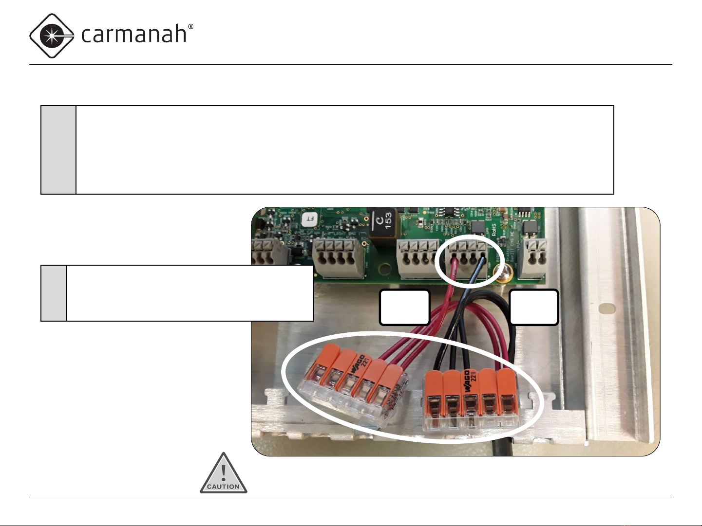
84703 Wago 221-413 3-position Splice Terminal 2
84705 Wago 221-415 5-position Splice Terminal 2
54246 Cable Tie, 4 Inch 2
84708 Wire, Hookup, 16AWG Red 6 Inch
84709 Wire, Hookup, 16AWG Black 3 Inch
89106 Heat Shrink Tubing, 3/8" ID, 2:1, Glue-Lined, black 1 Inch
89104 Install Guide, AI Integration Kit, F-Series 1
1.4 Applications
For Carmanah R829-F and R247-F systems, the F Series AI Integration Kit allows for remote system monitoring, scheduling and control. With
Carmanah R820-F and R920-F Rectangular Rapid Flashing Beacon (RRFB) systems, the F Series AI Integration Kit allows remote system
monitoring.

Page 5
F Series
APPLIED INFORMATION (AI) INTEGRATION INSTALL GUIDE
Carmanah Technologies Corp. | 250 Bay St, Victoria, BC V9A 3K5, Canada | 1.250.380.0052 | customerservice@carmanah.com | carmanah.com
2.0 Tools and Materials Required
The following tools and materials may be required to install the AI Integration Kit into your F Series system:
•Drill and ½” drill bit
• Deburring tool or similar
•Crescent wrench
•Side cutters
•Heat gun
•3/32” flat blade screwdriver
•Multi-bit screwdriver
•Electrical multimeter

Page 6
F Series
APPLIED INFORMATION (AI) INTEGRATION INSTALL GUIDE
Carmanah Technologies Corp. | 250 Bay St, Victoria, BC V9A 3K5, Canada | 1.250.380.0052 | customerservice@carmanah.com | carmanah.com
Drill Hole for Antenna
1
•Use the indentation to locate the tip of the drill bit.
•Drill a ½” hole on top of the enclosure.
•Deburr hole and remove all aluminum chips.
Ensure equipment is not powered
during installation and wiring of
the system. Recheck all completed
wiring for proper polarity prior to
energizing the system.
Ensure all metal chips are removed
to prevent system damage caused
by short circuits.
Ensure that no burrs are present
that would interfere with the
antenna seal.

Page 7
F Series
APPLIED INFORMATION (AI) INTEGRATION INSTALL GUIDE
Carmanah Technologies Corp. | 250 Bay St, Victoria, BC V9A 3K5, Canada | 1.250.380.0052 | customerservice@carmanah.com | carmanah.com
Prepare AI Harness
2
•Obtain AI harness.
•Cut and remove terminals of the five wires shown
(violet, blue, black, red and yellow).
•Leave green wire ring terminal intact (not shown).
4
•Install provided heat-shrink tubing around the five wires
4.25” from end of black wire (other wires will end up
being longer).
•Use heat gun to affix the heat shrink tubing.
5•Strip insulation of the five wires 0.35”.
3
•Cut yellow wire to same length as black wire.
•Cut a three-inch section of yellow wire and strip each
end 0.35”, for use later.
3”
Discard
leftover
wire
4.25”

Page 8
F Series
APPLIED INFORMATION (AI) INTEGRATION INSTALL GUIDE
Carmanah Technologies Corp. | 250 Bay St, Victoria, BC V9A 3K5, Canada | 1.250.380.0052 | customerservice@carmanah.com | carmanah.com
Remove EMS Screws
If radio is present, ensure radio pins are not bent and antenna cable is not damaged.
6
•Unlatch and swing the solar panel open.
•Remove the four EMS cover screws.
•Swing the EMS down to access the
internal wiring.

Page 9
F Series
APPLIED INFORMATION (AI) INTEGRATION INSTALL GUIDE
Carmanah Technologies Corp. | 250 Bay St, Victoria, BC V9A 3K5, Canada | 1.250.380.0052 | customerservice@carmanah.com | carmanah.com
Remove Battery Harness Wires from Circuit Board (EMS)
7•Remove battery harness wires from battery circuit board terminal by pushing down on
each terminal button with small flat bladed screwdriver and pulling out each wire.

Page 10
F Series
APPLIED INFORMATION (AI) INTEGRATION INSTALL GUIDE
Carmanah Technologies Corp. | 250 Bay St, Victoria, BC V9A 3K5, Canada | 1.250.380.0052 | customerservice@carmanah.com | carmanah.com
Install Battery Jumper Wires and Splice Terminals
Red
wires
Black
wires
8
•Obtain 3” of red and 3” of black wire supplied with the kit.
•Strip ends of both wires 0.35”.
•Use small flat bladed screwdriver to depress each terminal button and insert the wire into the terminal.
•Install one end of the red wire into the left BAT+ terminal.
•Install one end of the black wire into the right BAT− terminal.
•Insert the other end of each wire into two of the 5-position splice terminals.
Make sure all wire strands go into the terminal hole.
9
•Route the two red battery harness wires into the
splice terminal with the red wire from BAT+.
•Route the two black battery harness wires into the
splice terminal with the black wire from BAT−.

Page 11
F Series
APPLIED INFORMATION (AI) INTEGRATION INSTALL GUIDE
Carmanah Technologies Corp. | 250 Bay St, Victoria, BC V9A 3K5, Canada | 1.250.380.0052 | customerservice@carmanah.com | carmanah.com
Install AI Harness
If the system has a push
button, insert the positive
push button wire into the
empty position of the 3-
position splice terminal.
Red
(BAT+)
Black
(BAT−)
Blue
(EXT1)
Red
(PBS+)
Violet and
red (splice
terminal
10
•Obtain 3” of red wire supplied with the kit and strip both ends to 0.35”.
•Insert one end of 3” red wire into PBS+ terminal.
•Route modified AI harness wires (from Steps 2 –5, violet, blue, black, red and yellow)
into the hole shown.
•Install the wires into the terminals as follows:
Violet 3-position splice terminal with red wire going to PBS+
Blue EXT1
Red Middle BAT+
Black Middle BAT−
11
•Align ends of heatshrink on both harnesses near end of
sheet metal tab.
•Cable tie around both harnesses and sheet metal tab.

Page 12
F Series
APPLIED INFORMATION (AI) INTEGRATION INSTALL GUIDE
Carmanah Technologies Corp. | 250 Bay St, Victoria, BC V9A 3K5, Canada | 1.250.380.0052 | customerservice@carmanah.com | carmanah.com
Install Solar Panel Jumper Wires and Splice Terminal
12
•Remove red solar panel wire from the
PV+ terminal.
•Insert red wire into 3-position splice
terminal.
13
•Insert one end of 3” yellow wire from
step 3 into PV+ terminal.
•Insert other end of 3” yellow wire into
3-position splice terminal.
•Insert yellow wire from AI harness into
third splice terminal position.

Page 13
F Series
APPLIED INFORMATION (AI) INTEGRATION INSTALL GUIDE
Carmanah Technologies Corp. | 250 Bay St, Victoria, BC V9A 3K5, Canada | 1.250.380.0052 | customerservice@carmanah.com | carmanah.com
Route Wires
14 •Tuck 3-position splice terminal under PV and battery harnesses as shown.
•Route wires as neatly as possible.

Page 14
F Series
APPLIED INFORMATION (AI) INTEGRATION INSTALL GUIDE
Carmanah Technologies Corp. | 250 Bay St, Victoria, BC V9A 3K5, Canada | 1.250.380.0052 | customerservice@carmanah.com | carmanah.com
Install Ground Ring Terminal
15
•Turn EMS over and replace four screws.
•Install ring terminal from green ground
wire under bottom right EMS screw.

Page 15
F Series
APPLIED INFORMATION (AI) INTEGRATION INSTALL GUIDE
Carmanah Technologies Corp. | 250 Bay St, Victoria, BC V9A 3K5, Canada | 1.250.380.0052 | customerservice@carmanah.com | carmanah.com
Install Antenna
16
•Route antenna coax connector cables into
enclosure hole and through plastic washer,
lock washer and nut.
•Tighten nut securely using crescent wrench.
18
•Thread coax adapters onto AI connectors.
•Match GPS & GSM labels on antenna harness
& AI unit (Cell closer to front, GPS closer to
back).
17
•Thread 90°coax adapters onto antenna
connectors. Orient as shown (facing upward
when installed into cabinet).

Page 16
F Series
APPLIED INFORMATION (AI) INTEGRATION INSTALL GUIDE
Carmanah Technologies Corp. | 250 Bay St, Victoria, BC V9A 3K5, Canada | 1.250.380.0052 | customerservice@carmanah.com | carmanah.com
Avoid sharp bends in the coax cable.
19 •Use four supplied screws to install AI
unit into enclosure with bracket.
20 •Install the connector from the EMS to
the AI unit.
21 •Route coax cables between AI unit and
antenna neatly and cable tie as needed.
Install AI Unit

Page 17
F Series
APPLIED INFORMATION (AI) INTEGRATION INSTALL GUIDE
Carmanah Technologies Corp. | 250 Bay St, Victoria, BC V9A 3K5, Canada | 1.250.380.0052 | customerservice@carmanah.com | carmanah.com
22 •Ensure AI serial number has been activated.
24 •Ensure connectors are properly mated on bottom of
AI unit.
25
•Confirm correct wiring and power-up system by
connecting the DC power, installing fuses and
turning on AI power switch.
26
•On your PC, open a browser and navigate to the
Glance website:
glance.appinfoinc.com/
27 •Login using the credentials provided by AI
28
•On the upper left side of the browser, select the
device name that matches the Device ID (the ID
number labelled on the AI unit).
Ensure the equipment is not powered during installation.
Recheck all wiring prior to energizing the system.
23 •For R920 or R820 systems, set toggle switch to
“OFF”. In all other cases, set to “AUTO”.
Test AI Unit

Page 18
F Series
APPLIED INFORMATION (AI) INTEGRATION INSTALL GUIDE
Carmanah Technologies Corp. | 250 Bay St, Victoria, BC V9A 3K5, Canada | 1.250.380.0052 | customerservice@carmanah.com | carmanah.com
Confirm Unit Available Through Glance User Interface
If testing indoors where there is no GPS
signal, this may result in a device status
of “No GPS Lock.”
R829 school zone application shown.
29 •Ensure that the “Current Status”
indicates “Online”.
30 •Ensure “Current Device Status” is OK.
31
•If required, contact Applied Information
for correct programming of AI firmware:
Phone: 678.830.2170
Email: support@appinfoinc.com
Web: appinfoinc.com

Page 19
F Series
APPLIED INFORMATION (AI) INTEGRATION INSTALL GUIDE
Carmanah Technologies Corp. | 250 Bay St, Victoria, BC V9A 3K5, Canada | 1.250.380.0052 | customerservice@carmanah.com | carmanah.com
© 2020 Carmanah Technologies Corporation
Technical Support:
Email: customerservice@carmanah.com
Toll Free: 1.877.722.8877 (US & Canada)
Worldwide: 1.250.380.0052
Fax: 1.250.380.0062
Web: carmanah.com
This manual suits for next models
2
Table of contents
Other Carmanah Inverter manuals