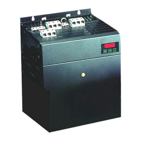
CLINTON INDUSTRIES 1190E User manual

CLINTON INDUSTRIES, INC
207 Redneck Ave. Little Ferry, NJ 07643
PHONE: 201 440 0400 / FAX: 201 440 5040
EMAIL: general@clintonind.com
1190E
Photo Eye / Back Tack / Trim Systems
Feb. 2011 by Peter Schueler, Clinton Ind., Inc.
Description about:
….. Introduction Page 1
…... Access to Hidden Parameters Page 2
……Master Reset Page 2
….. Mode of Operations Page 3
….. Parameters (Operators) Page 4
….. Parameters (Advanced, “Hidden”) Page 6
….. Trim Systems Page 10…
….. Built-in Test Procedure Page 11
….. Display the Program ID Page 13
….. Two Indicator LED’s at front Page 13
….. How to program a memory Page 13
….. Safety Switch Page 14
….. Trouble Shooting: Page 15
-- 1 --

There is a slightly difference between the older 900er series and the new M16
system.
Power-On:
Never connect the motor (power or encoder cable)
after the power is turned ON !
LCD- display box (Programmer)
To connect or disconnect the LCD- box, the power has to be turned off
to initialize the system after power-on
Going to the “Hidden Parameters” or “MASTER RESET”:
Please read the procedure carefully at page 3
The new system with the large motor needs a synchronizer, mounted to the
hand wheel.
Synchronizer discs:
Outer disc: Needle-UP
Middle disc: Needle-DOWN
Inner Disc: Trim
Pulley ratio:
In order to get the selected speed at the sewing machine and not at the motor,
The pulley ratio between motor pulley and machine pulley (hand wheel) has to
be taken.
This happens after a “MASTER RESET” or a special procedure to take the
ratio. The display reads: “TAKE NEW RATIO”
The ratio is verified after each power-on.
In case of the change of the pulley, new ratio will be taken.
How to force to take a new ratio:
1. The power has to be turned on.
2. Press the “NEEDLE-UP/NEEDLE-DOWN” and the “SBT” buttons at the
same time.
3. Turn the power off.
4. Wait for the message “GOOD BYE< SEE YOU”
5. Turn the power back on before the message disappears
6. Held both buttons down until the massage “RELEASE BUTTONS”
appears.
7. Release the buttons. Now the display should read “TAKE NEW RATIO”
-- 2 --

Access to “HIDDEN PARAMETER”
A) If the power is OFF, turn it ON (the display reads “OPERAION MODE”)
B) Turn the power OFF (the display reads “good bye, see you”)
C) Hold down the “NU/ND”, and the “ARROW-RIGHT” buttons
D) Turn the power back ON before the display gets blank (very important!)
E) Held the buttons down until a string of stars is displayed.
F) Release the buttons and push the “SET” button before the stars disappear. The access
to the “HIDDEN PARAMETER” is enabled.
Power OFF will disable the access.
MASTER RESET
Caution: This procedure will overwrite the whole parameter set with the default settings!
A) If the power is OFF, turn it ON (the display reads “OPERAION MODE”)
B) Turn the power OFF (the display reads “good bye, see you”)
C) Push and hold down the “NU/ND”, the “ARROW-RIGHT” and the “ARROW-UP”
buttons
D) Turn the power back ON before the display gets blank (very important!)
E) Held the buttons down until the displayed message alternates between:
“PUSH SET” and “FOR RESET”
F) Release the buttons and push the “SET” button within ten (10) cycles.
The display reads: “PROGRAMMING”
NOTE: if the “SET” button is not pushed within 10 cycles, the program goes to the main
menu without executing the MASTER RESET.
Access to the “HIDDEN PARAMETER” is enabled to make important settings such as
speeds and needle-positions.
--3--

MODES OF OPERATION:
The LCD display can be operated in three (3) different modes.
They are:
1. OPERATING MODE: To operate the machine
2. PROGRAMMING MODE: To change a parameter
3. TEST MODE An easy way to maintain and check the system.
Two different parameter levels are available:
OPERATORS LEVEL (Basic)
MECHANICS LEVEL (Advanced)
To use the MECHANICS LEVEL, please see the section 2.0.0 (Access to “HIDDEN
PARAMERTERS)
1.0.0. HOW TO CHANGE A PARAMETER:
Four parameter groups are available (OPERATORS LEVEL)
SPEEDS
TIMERS
COUNTERS
TOGGLE SWITCHES.
To change a parameter, please proceed the following sequence:
STEP 1
Push the ‘ARROW ROUND’ button repeatedly until the desired parameter group is displayed.
STEP 2
Push the ‘SET’ button repeatedly until the desired parameter is displayed
STEP 3
Change the parameter with the buttons:
‘ARROW-UP’ (increase the value)
or ‘ARROW DOWN’ (decrease the value)
In the group ‘TOGGLE SWITCHES’ , either button, “ARROW UP” or “ARROW DOWN”
will toggle the parameter.
PLEASE NOTE:
To optimize a certain parameter, it may be necessary to go repeatedly from the operation mode
back to the same parameter.
It can be easy done by pressing the ‘SET’ button.
If the program is in the OPERATION MODE, the SET button takes you right back to the last
displayed parameter.
Exemption:
If you are in the group “TOGGLE SWITCHES”, the “SET” button brings you to the first parameter of the
group “TOGGLE SWITCHES”
If a parameter was changed by accident and the machine doesn’t work properly, it is possible
to go back to the original factory setup by using the feature of the MASTER RESET (section 3.0.0).
-- 4 --

4.0.0 Operators Parameters:
4.0.0 SPEEDS: rpm (spm, stitches per minute)
4.0.1 Soft Strt. Soft start after End of Cycle
Range: 150 to 1000
Steps: 10
Default: 700
4.1.0 TIMERS ms (milliseconds)
4.1.1 Strt Del. Start Delay
The delay from presser foot down to start.
If the foot is already down, this time will not affect.
Range: 30 to 2500
Steps: 10
Default: 60
4.1.2 TR-stp Trim
Clinton trim system: Stop time
If this time is zero (0), the machine will not stop
Chain stitch: Trim-on time
Range: 0 to 2500
Steps: 10
Default: 80
4.1.3 Wiper Wiper Time
Range: 10 to 2500 (large timer for pneumatic wiper)
Steps: 10
Default: 80
4.1.4 INTERL Interlock time The time a new start is suppressed after trim
Range: 10 to 300
Steps: 10
Default: 30

-- 5 --
4.4.0 COUNTERS, (Numbers of Stitches)
4.3.1 SOFT ST (SOFT or SLOW START)
Number of stitches sewn with limited speed (4.1.2)
after restart from EOC
Range: 1 to 25 stitches
Steps: 1 stitch
Default setting: 2 stitches
4.3.2 SBT forw Start (Front) back tack forward
Range: 1 to 200 stitches
Steps: 1 stitch
Default setting: 4 stitches
4.3.3 SBT rev Start (Front) back tack reverse (backward)
Range: 1 to 200 stitches
Steps: 1 stitch
Default setting: 4 stitches
4.3.4 EBT rev End back tack reverse
Range: 1 to 200 stitches
Steps: 1 stitch
Default setting: 4 stitches
4.3.5 EBT forw End back tack forward
Range: 1 to 200 stitches
Steps: 1 stitch
Default setting: 4 stitches
4.3.6 EYE Off Photo Eye offset stitches
Range: 1 to 200 stitches
Steps: 1 stitch
Default setting: 10 stitches
-- 6 --

4.6.0 TOGGLE SWITCHES
4.5.1 PF/EOC Presser Foot End of Cycle UP / DOWN
Default: DOWN
4.5.2 PF/seam Presser foot in the seam UP / DOWN
Default: DOWN
4.5.3 Pos in Cyc Needle Position in Cycle UP / DOWN
Default: DOWN
4.5.4 Soft Start ON / OFF
Default: OFF
4.4.5 START PED: neutral **
START PED: always ***
Default: always
** After trim: The pedal has to be in the neutral position in order to restart the
machine.
*** After trim: The machine restarts without the pedal was in neutral position.
5.0.0 HIDDEN PARAMETER
5.1.0 ***** SPEEDS (rpm)
5.1.1 MIN/TRM Minimum and Trim Speed
Range: 30 to 600
Steps: 10
Default: 230
5.1.2 MAXIM. Maximum Speed
Range: 500 to 9000
Steps: 100
Default: 4500
-- 7 --

5.4.0 ****** MISCELEN (Miscellaneous)
Presser foot duty cycle:
Due the voltage is too high to turn a solenoid permanent on all time,
the current is turned on only permanently a short time, after that,
the current has to be chopped.
For example: Duty cycle 40% means 40% on, 60% off
If the duty cycle is too low, the solenoid will not stay on.
If too low, the solenoid will turn too hot!
5.4.1 PF 100% Presser foot on 100 %
Range 10 to 2000
Steps: 10
Default: 200
5.4.2 PF DUTY Presser foot duty cycle
Range 10 to 100
Steps: 10
Default: 50 (50%)
Acceleration / Deceleration Ramp:
The lower the number, the slower the Ramp!
5.4.3 ACCEL Acceleration ramp
Range 15 to 50
Steps: 1
Default: 40
5.4.3 DECEL Deceleration ramp
Range 15 to 50
Steps: 1
Default: 40
-- 8 --

5.5.0 ****TOGG SW TOGGLE SWITCHES
5.5.1 DIRECTN Direction of Rotation (CCW / CW)
Default: CW (Clockwise )
5.5.2 START The next start after end of cycle
the front eye (eye 2) must be covered or not covered
Default: covered
5.5.3 POSITION fast or normal
Default: normal
5.5.4 SHOW REGS “NO” / “YES”
Default: NO Do not CHANGE !
5.5.5 Turn back “ON” or “OFF”
Default: OFF
5.5.6 LIGHT / HEAVY MACHINE
Default: LIGHT
-- 9 /10 --

7.0.0 Trim Systems:
IMPORTANT:
Before selecting the system, the positions of the needle have to be set. Otherwise it
may cut the needle and the trim system gets destroyed.
For this reason, the default is: “NO TRIM SYSTEM”
LOCK STITCH SYSTEMS
“Needle-up”: Take-up upper dead point center (lock stitch)
Needle in upper dead point center (chain stitch)
“Trim” Turns on the trim signal, used in trim systems
without cam. (lock stitch only)
How to set: Take-up down (when the needle
thread crosses the bobbin
“Needle-down” see specs of the manufacturer
1. CLINTON:
The machine stops in the take-up’s lower dead point center for
the stop-time (parameter group “TIMER”). During the stop,
the trimmer gets activated. After the stop time, the machine
goes in take-up up position and the trim signal turns off.
2. JUKI / DUERKOPP:
The trim signal gets activated in needle-down position and
stays on to take-up up position (cam guided system)
3. PFAFF MECHANIC:
Same as Duerkopp except the trim signal turns off in take-up
down position
4. BROTHER / PFAFF pneumatic:
Same as CLINTON lock stitch, but without stop at take-up
down position
CHAIN STITCH SYSTEMS:
Selecting the Chain Stitch Trim System enables the safety switch.
Trim in “NEEDLE-UP”. If the needle is already in up-position, the machine will not
Reposition if the machine is not more then+/- 10 degrees out of position.
Trim sequence in needle-up position:
TRIM turns on. After 50% of the trim time, tension release turns on. After the full
trim time, TRIM turns off. After 35 milliseconds, tension release turns off and the
wiper gets activated for the wiper time.
` --11--

7.1.0 Using the Built-in Test Program
To enter: Press simultaneously the ARROW- RIGHT and the SBT button., release the
ARROW-RIGHT button first! Otherwise you are back in the main program!
The display should read: TEST MODE
To go to the first group, press the “ARROW-ROUND” button
The display reads: TEST TREADLE for about 2 seconds
Then it reads the position of the threadle:
This can be: 1. NEUTRAL
2. FORWARD and a number
B) HEEL 1
C) HEEL 1 / HEEL 2
If the threadle is in forward position, the displayed number is the reading of the
ADC- converter.
The lowest number should be below ten (10) and the highest number at least 245
To go to the next group, press the “ARROW-ROUND” button again
The next group is: test synchronizer
Turn the hand wheel and the display reds all 3 positions:
NEEDLE-UPor/ NEEDLE-DOWN or TRIM
To go to the next group, press the “ARROW-ROUND” button again
The next group is: test inputs
(this will be displayed for two seconds)
Then activated inputs are displayed
If no inputs are activated, the display reads “ ---------------- “
To go to the next group, press the “ARROW-ROUND” button again
The next group is: test outputs
After two seconds, the display reads: -1- PRESSERFOOT
To activate the output, press the “NEEDLE-UP / NEEDLE-DOWN button.
To go to the next output, press the “ARROW-UP” button.
The next reading is; - 2 – NEEDLE COOLER
To go to the next output, press the “ARROW-UP” button.
To go to the former output, press the “ARROW-DOWN” button

--12--
To go to the next group, press the “ARROW-ROUND” button again
The next group is: Test Encoder / Index
The LCD- display reads the number of pulses of the encoder. Turn the hand wheel
And the number counts up or down, dependent on the direction. The index signal
resets the counter at 2000 (up) or 1 (down). If the encoder counts up and the
number changes at 2000 to 1, every thing is fine.
To go to the next group, press the “ARROW-ROUND” button again
The next group is: Test Motor (Balance)
This test allows testing the “balance” of the motor. If this adjustment is not
correct, the motor turns hot while operating.
To perform the test the motor has to be disconnected from the machine.
Push the NU/ND- button, the motor starts running with a low speed (100 rpm) for
about three revolutions. The display reads: “WAITING FOR INDEX”
After the motor stops, the following message will be displayed:
“CALCULATE OFFSET”. When the offset is calculated, the result will be
displayed: “ADJUSTMENT: + xx “ or “ADJUSTMENT – xx”
“+xx” or “- xx” represents a number. This number should not be higher then 15.
If the reading is not correct, please repeat the test (Press NU/ND again).
5.6 counts is one degree.

--13--
Display the PIN (Program Identification Number)
1. Turn the power OFF
2. Press the pedal forward
3. Turn the power ON while the pedal is held in the forward position
(Don’t worry, the machine (Motor) will not move)
4. The LCD- display reads the PIN as long as the pedal is held down
Indicator LED’s at the front panel:
Yellow: No encoder pulses detected at power-on
The program could not set the position of the hand wheel. Check
the encoder pulses !
Red: Over current error (Motor)
`
Download a “HEX”- file to program a memory chip (E- prom)
for the new M16 system:
The external program for the M16 system starts at address “F0000” HEX and ends at
“FFFFF”
The addresses from 00 to “EFFFF” are reserved for the internal ROM (or flash memory) of
the CPU.
Because the .ORG of the program is set to “F0000hex the program will be downloaded at a
higher address (This depends on the size of the buffer of your programmer.
A) Fill the buffer of your programmer complete with “FF”hex
(recommended)
2. Download the hex file into the buffer of your programmer
3. Check out where the program starts. This can be “70000” or “F0000”
This address depends on the size of the programmers memory.
A) Move the complete hex file to address “00000” and program the e- prom.
Your programmer has no “MOVE” command?
In this case you change the starting address of the buffer from “0000” to the address
where the program starts.
Keep the device address “0000”

-- 14 /15 --
TROUBLE SHOOTING
IN GENERAL:
All units have to pass strong test procedures.
They are tested from the
1. MANUFACTURER
2. CLINTON INDUSTRIES
The test at CLINTON INDUSTRIES includes:
a) Cycling the unit under normal conditions for about 6 hours
b) 1st Stress test
c) Vibration test
d) 2nd Stress test
e) Full function test
Most failures happen because of :
1. Improper grounding.
Static voltage at different parts of the machine may cause serious
problems.
Large Motor:
CLINTON INDUSTRIES provides a braided ground wire which has
to be connected between sew head and control box.
Mini Taurus:
If the motor is attached to the sew head, the system is grounded thru the
motor
a) The power supply system has to be grounded properly.
b) Additional attachments like stackers etc. needs to be grounded too.
2. Improper connections
a) Connections between control box and motor
b) Connections between control box and attachments.
c) Connection to the power supply system.
Please note:
Certain tests require to disconnect the motor from the machine.
If you do so and mount the motor back, you will loose the
positions of the machine. (Needle-up, Needle-down and Trim)

--16--
Trouble Shooting Guide:
Turn the power on and the display stays blank: No power at all !
1. Is the display box plugged in properly?
2. Check the line voltage
3. Check the power plug for proper connection
4. Check the power switch
5. Turn the power off, Unplug all connections except the power
plug and the LCD- display box and turn the power back on.
Still blank? If yes,
Try another LCD- display box.
6. If this fails, replace the control box.
Turn power on and the display has 8 black bars at the left hand side:
The power supply seems O.K. but the program doesn’t run.
1. The LCD- box is not properly connected
2. The LCD box was plugged-in during “POWER ON” (not
initialized)
To connect a LCD- box, the power has to be turned off before
the LCD- box gets plugged-in.
3. Check logic board for LCD- box jumpers (see logic board
drawing).
The motor runs properly, but the solenoids don’t work:
The power supply for the transformer is missing.
The transformer is only used to operate the solenoids
1. Open the control box and check the plug which connects the
transformer to the output board (3-pin plug, two yellow and
one green wire)
2. Check the connection of the black ribbon cable between
solenoid board (CN5) and logic board (CN1)
3. Check the fuse “F1”on the solenoid board.
4. Go to the “TEST MODE, TEST OUTPUTS and check all
outputs for function

--17 --
The unit has a “strange” behavior:
An important parameter may have been changed by accident.
1. Make notes about your parameter setups.
2. Proceed a “MASTER RESET” (see MASTER RESET
instruction)
3. Test the machine for proper function.
4. Reprogram the machine step by step to your original setup.
5. Please remember to check the positions and the direction
carefully before you start the machine.
The motor gets too hot:
1. Go to the SYSTEM TEST and check the balance of the motor
see the manual for “ system test instruction”
2. Check the machine head. The machine head should turn
freely.
The position stop points are not matching correctly with the adjustment made with
the “teach-in” mode:
Please return back to the parameter and make the final
adjustments in small increments with the ARROW UP / DOWN
button.
Don’t use the “TEACH-IN” mode to change small amounts.
The position is erratic and/or migrating:
3. Go to the “SYSTEM TEST” routine and test the balance of
the motor.
4. Make sure, the position point is slightly before the top center.
5. Check the LOVEJOY coupling at the motor and machine
shaft for proper tightness.

-- 18 --
WATCHDOG ERROR:
IN GENERAL:
A watchdog error occurs, when the feedback from the motor to
the processor is missing. That means, the processor does not
receive the encoder pulses.
In case of a watchdog error, please proceed the following:
Press the NEEDLE UP / DOWN button, the program will go
back to the operation mode.
Start again.
If the machine operates normal:
1. Check the motor plugs for proper connection
2. Check the temperature of the motor.
3. If the motor turns too hot, check the mech. part of the
machine
4. Run the test for the balance of the motor.
If the machine turns about one revolution with uncontrolled speed:
The encoder pulses are missing.
1 Check the encoder plug for proper connection.
2. Run the encoder test
If the machine does not run at all:
1. Check all motor plugs for proper connection
2. Check your line voltage (must have at least 180 volt).
3. Remove the motor and run the motor test.
4. Check the overload LED (red LED at the front of the control
box).
If the LED is lit, turn the power off and wait at least one minute.
Turn the power back on.
If the machine runs normal, a spike may have caused the
problem.
CHECK FOR PROPER GROUNDING.
Check the ferrites on the following cables:
LCD box input, encoder input and pedal input.

Table of contents
Popular Controllers manuals by other brands

National Instruments
National Instruments CompactRIO cRIO-9002 operating instructions
SOMFY
SOMFY animeo IB + 1822064 installation guide

Dover
Dover HYDRO Multi-Washer 3000 Series user manual
Signet
Signet GF 5600 manual
PIETRO FIORENTINI
PIETRO FIORENTINI REFLUX 819/FO Technical manual

Mitsubishi Electric
Mitsubishi Electric QJ71AS92 user manual
