Clinton 970 User manual

CLINTON
MODEL 970
VARIABLESPEED
DC SERVO MOTOR
SERVICE MANUAL
ML970-3
NEEDLE POSITIONER THREAD TRIMMER
40-0258-01

TABLE OF CONTENTS
®
ML970-4
SECTION I - INTRODUCTION . . . . . . . . . . . . . . . . . . . . . . . . . . . . . . . . . . . . . . 1-1
SECTION II - INSTALLATION . . . . . . . . . . . . . . . . . . . . . . . . . . . . . . . . . . . . . . 2-1
A.
B.
C.
D.
E.
F.
MOTOR . . . . . . . . . . . . . . . . . . . . . . . . . . . . . . . . . . . . . . . .
LCD DISPLAY . . . . . . . . . . . . . . . . . . . . . . . . . . . . . . . . . . .
SWITCH BOX . . . . . . . . . . . . . . . . . . . . . . . . . . . . . . . . . . . .
POWER AND CABLE CONNECTIONS . . . . . . . . . . . . . . . . .
MOTOR ROTATION . . . . . . . . . . . . . . . . . . . . . . . . . . . . . . .
TEACH-IN MODE . . . . . . . . . . . . . . . . . . . . . . . . . . . . . . . . .
2-1
2-1
2-2
2-2
2-2
2-3
SECTION III - PROGRAMMABLE LCD DISPLAY . . . . . . . . . . . . . . . . . . . . . . . 3-1
A.
B.
C.
DIRECT ACCESS PARAMETERS . . . . . . . . . . . . . . . . . . . .
HIDDEN PARAMETERS . . . . . . . . . . . . . . . . . . . . . . . . . . .
MASTER RESET . . . . . . . . . . . . . . . . . . . . . . . . . . . . . . . . .
3-1
3-2
3-3
SECTION IV - TEST PROGRAM 4-1
1. TREADLE TEST. . . . . . . . . . . . . . . . . . . . . . . . . . . . . . . . .
2. INDEX SIGNAL . . . . . . . . . . . . . . . . . . . . . . . . . . . . . . . . .
3. ENCODER TEST. . . . . . . . . . . . . . . . . . . . . . . . . . . . . . . .
4. MOTOR BALANCE TEST . . . . . . . . . . . . . . . . . . . . . . . . .
4-1
4-1
4-1
4-1
SECTION V - CONNECTOR DIAGRAMS . . . . . . . . . . . . . . . . . . . . . . . . . . . . . . 5-1
SECTION VI - DRAWINGS AND PARTS LIST . . . . . . . . . . . . . . . . . . . . . . . . . . . 6-1
A.
B.
C.
D.
E.
F.
G.
MAJOR ASSEMBLIES . . . . . . . . . . . . . . . . . . . . . . . . . . . . . .
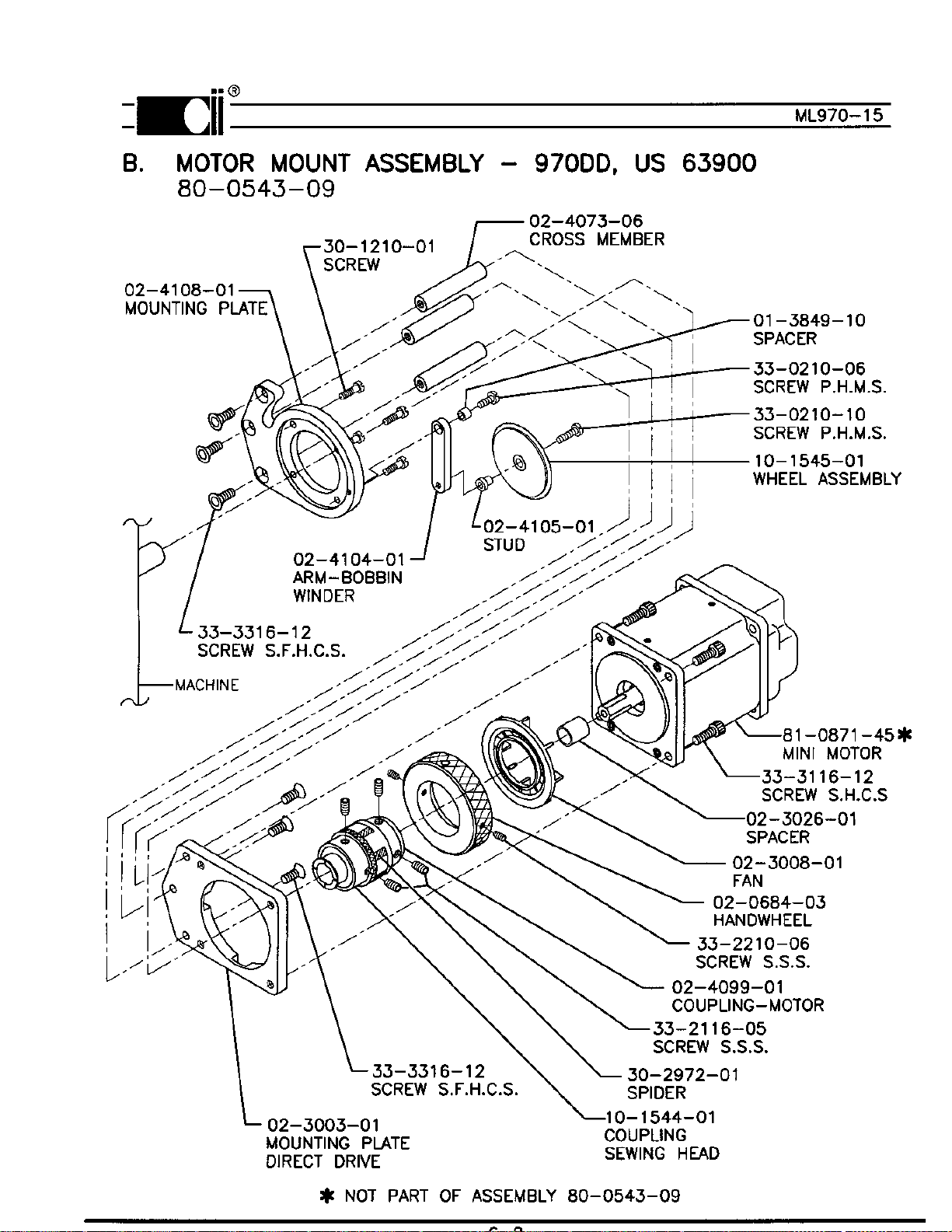
MOTOR MOUNTING ASSEMBLY . . . . . . . . . . . . . . . . . . . . .
CONTROL BOX ASSEMBLY . . . . . . . . . . . . . . . . . . . . . . . . .
POWER SUPPLY . . . . . . . . . . . . . . . . . . . . . . . . . . . . . . . .
PROGRAMMABLE DISPLAY . . . . . . . . . . . . . . . . . . . . . . . . .
MISCELLANEOUS PARTS . . . . . . . . . . . . . . . . . . . . . . . . . .
E-PROM . . . . . . . . . . . . . . . . . . . . . . . . . . . . . . . . . . . . . . . .
6-1
6-2
3-3
6-4
6-5
6-5
6-5

INTRODUCTION
Clinton's Model 970 is an electronically controlled variable speed drive for industrial sewing machines.
The drive consists of a brushless DC Servo Mini-Taurus motor, controller with a microprocessor, speed
control and a programmable LCD display as an option. No clutches, brakes or synchronizer are used.
All components interact to give a fast accurate and reliable sewing machine drive. The components of
the system are shown in figure below.
The model 970 has outputs for a trimmer, footlift, wiper and needle cooler. It can be used to operate all
Clinton trimmers, as well as the Singer, Union Special, Pfaff, Juki and Brother undertrimmers and chain
stitch machines.
The programmable LCD display is used to select the trimmer type and other parameters.
See section III.
1-1
®
SECTION I ML970-5
MINI-TAURUS
SWITCH BOX
CONTROL BOX
LCD
DISPLAY

INSTALLATION
A. MOTOR INSTALLATION
1. Remove the handwheel from the machine.
2. Remove the four screws that hold the bearing housing to the machine, see ML970-15. Attach
the sewing head mounting plate, 02-4108-01 to the machine with the screws provided
30-1210-01.
3. Attach the sewing head coupling assembly 10-1544-01 to the machine removing all play from
the main shaft.
4. Rotate the machine in the standard direction of rotation until the point of the needle is even with
the top of the throat plate.
5. With power to the system and the motor detached from the machine press the "arrow right" and
"SBT" buttons simultaneously. The display will read "TEST SYSTEM" briefly the "PRESS
SET".
6. Press the "SET" button twice, the display will read "TEST INDEX" briefly then show a broken
line (---------) rotate the motor slowly by hand until the display reads (---INDEX---).
7. Align the motor coupling with the sewing head coupling, keeping the motor in the INDEX posi
tion, and attach the motor to the machine.
Note: The sewing head may have to be rotated slightly in order to align the couplings but
the INDEX signal must be between the needle up and the needle down positions.
B. LCD DISPLAY
Mount the LCD display console at
a convenient location on the table top
as shown in figure 2-2.
SECTION II
®
ML970-6
2-1
Fig. 2-2
NEEDLE UP
NEEDLE DOWN
TRIM
INDEX
DIRECTION OF
ROTATION
Fig. 2-1

C. SWITCH BOX
Install switch box at a convenient
location under the table. See fig. 2-3.
D. POWER AND CABLE CONNECTIONS
Refer to figure 2-4 and connect all cables as shown. The system can be operated from 230V, 3
phase or 230V, single phase power.
2-2
E. MOTOR ROTATION
Before attaching the motor to the sewing head, turn power on, then move the pedal forward and
note the direction of motor pulley rotation. If incorrect, do the following:
1. Turn power off.
2. Refer to section III-B, Hidden Parameters, and follow the instructions to change motor rotation.
The parameter is in the "**** Toggle Switches" group.
3. Install the motor.
FIG. 2-4
®
ML970-7
Fig. 2-3
CABLE DIAGRAM

F. TEACH-IN MODE
(SETTING THE NEEDLE UP, NEEDLE DOWN AND TRIM POSITIONS)
Note: The index signal from the motor must be set prior to setting the needle up and down posi-
tions. (See systems test section for instruction on setting the index signal).
1. NEEDLE DOWN
To set the needle down position access the "****MISC." group of the hidden parameters then
select the "NEED.dwn" parameter. Rotate the handwheel of the machine until the needle is in
the down position. Press the treadle forward, the machine will make one revolution then save
the needle down position.
2. NEEDLE UP
To set the needle up position access the "****MISC." group of the hidden parameters then select
the "NEEDLEup" parameter. Rotate the handwheel of the machine until the take-up lever is in
dead center position. Press the treadle forward, the machine will make one revolution then save
the needle up position.
3. TRIM
To set the trim position access the "****MISC." group of the hidden parameters then select the
"TRIMcnt." parameter. Rotate the handwheel of the machine until the needle thread is posi
tioned between the 5 and 6 o'clock position across the hook. The needle is used for the refer
ence point of 12 o'clock position. Press the treadle forward, the machine will make one revolu
tion then save the trim position.
Note: Any of the above positions may be "Fine Tuned" by accessing their respective parameter and
using the or button to change the displayed value.
2-3
®
ML970-7-1

PROGRAMMABLE LCD DISPLAY
The LCD display, shown in fig. below is used to program and set the various parameters of the 970;
SPEEDS, TIMERS, COUNTERS, and TOGGLE SWITCHES.
Two (2) different modes of operation are
available. They are:
1. Operating Mode
2. Programming Mode
When power is turned on, the display
is in the operating mode.
There are two (2) groups of parameters that are accessed in different ways. They are : (1) parameters
with direct access and (2) hidden parameters with indirect access. In addition a master reset is avail-
able to reset all parameters to their default values.
A. DIRECT ACCESS PARAMETERS
The direct access parameters are divided into four (4) groups. They are (1) SPEEDS, (2) TIMERS,
(3) COUNTERS, and (4) TOGGLE SWITCHES. Table 3-1 describes each parameter, shows
the default value and range of adjustment for each parameter.
3-1
®
SECTION III ML970-8
To change a parameter, follow the sequence described below.
1. Press the key to enter the programming mode. Continue pressing this key until the para-
meter group that is to be changed is displayed. As an alternative; press the key to enter
the programming mode and display the last changed parameter.
2. Press the key to step to the next parameter in the selected group.
3. Press the key to increase or the key to decrease the contents of the displayed para-
meter. Both keys are used to toggle parameters between states in the Toggle Switches group.
Hold the key down to make the display step automatically.
4. Press the key to return to the operating mode.

®
3-2
B. HIDDEN PARAMETERS
The parameters in this section are separated from the Direct Access parameters because they are
infrequently changed and should not be changed by the operator. The parameters are listed in
table 3-2.
1. Turn power off, if it is on, then wait until the display goes blank.
2. Press the key and the key simultaneously. Keep pressed then,
3. Turn power on. A series of "***" will appear on the display. They will slowly dissapear.
4. Release the keys then press the key before all the stars dissapear.
5. Press the key repeatedly, until the first hidden parameter group (****SPEEDS) is dis
played.Note that 4 stars (*) as described in section "A" above.
PARAMETER DESCRIPTION DEFAULT RANGE
SPEED GROUP RPM RPM
SOFTSTRT Sets the RPM of the machine while in the soft
start option. 500 140-2000
TIMER GROUP MS MS
START DEL
TRIM TIME
WIPER TIME
Delays machine start to allow presser foot to
drop.
Sets the amount of time that the trimmer is on.
Sets the amount of time that the wiper is on.
80
90
80
10-500
50-250
10-250
COUNTER GROUP STITCHES STITCHES
SOFTSTRT Number of stitches sewn at soft start speed. 31-50
TOGGLE SWITCHES
PF/SEAM
PF/EOC
SOFT STRT
HEEL 2
Presser foot UP or DOWN in the seam, treadle
neutral.
Presser foot UP or DOWN at the end of cycle,
pedal neutral.
Turns the soft start function On or OFF.
Turns the trim function On or OFF.
DOWN
DOWN
OFF
ENABLED
UP/DOWN
UP/DOWN
ON/OFF
ENABLED/
DISABLED
TABLE 3-1
ML970-9

3-3
®
C. MASTER RESET
In some cases it may be necessary to reset all parameters to their default values. This is done as
follows:
1. Turn power off, if it is on, then wait until the display goes blank.
2. Press the key, key and key simultaneously. Keep pressed then,
3. Turn power on. The display alternates between "Push Set" and "For Reset".
4. Push the key within 10 cycles.
5. The word "Programming" is displayed. The parameters will be reset to their default values after
a few seconds.
TABLE 3-2
ML970-10
PARAMETER DESCRIPTION DEFAULT RANGE
****SPEED GROUP RPM RPM
TRIM/POS
MAXIMUM
Sets the
p
ositionin
g
s
p
eed of the achine
Sets the axi u s
p
eed of the achine
220
4200
100-250
500-9900
****MISCELLANEOUS
POS. DOWN
POS. UP
TRIM COUNT
PF DUTY
REVERSE COUNT
Sets the Needle Down
p
osition.*
Sets the Needle U
p
p
osition.*
Sets when the tri er activates.*
Avera
g
e volta
g
e a
pp
lied to the
p
resser foot
solenoid.
Sets the a ount the achine will turn back
if the reverse ode is activated.
130
210
140
5
3
0-255
0-255
0-255
1-10
0-255
****TOGGLE SWITCHES
DIRECTION
TRIM
REVERSE MODE
Sets the otor direction.
++CW = Clockwise
--CCW = Counterclockwise.
2 Position = The achine will not sto
p
when
the tri er is activated.
3 Position = The achine sto
p
s when the
tri er is activated.
Turns the reverse function On or Off.
--CCW
2 POS.
DISABLED
++CW / --CCW
2 POS. / 3 POS.
ENABLED /
DISABLED
* See Section II, Teach-in mode.

®
ML970-11
SECTION IV
TEST MODE
A. BUILT-IN TEST PROGRAM
A test program is available to test the major functions for a proper operation. To access the program
press the and buttons simultaneously.
The display will read "SYSTEM TEST" briefly then press "SET", after which the following may be
tested: TREADLE, INDEX SIGNAL, ENCODER, MOTOR BALANCE
1. Treadle Test
Press the button until "TEST TREADLE" will be displayed briefly then "NEUTRAL".
a. Move the pedal from neutral to heel 1 then to heel 2. The display should show each position.
b. Move the pedal forward slowly. As the pedal is moved, a number (0 to 255) will be dis
played.
Note: This number is proportional to how far the pedal is moved. The lowest number should
be no more than "8" and the highest number greater than "250".
2. Index Signal
Press the button. The display will read "TEST INDEX" briefly then show a broken line
"-------". Rotate the motor by hand until the display shows "----INDEX----" signal. If this signal is
not displayed within one revolution of the handwheel, the encoder has failed.
3. Encoder Test
CAUTION:Separate the coupling. The coupling must be separated because the motor may not
develop sufficient torque to turn the machine.
Press the button. The display will read "TEST ENCODER" briefly then "PUSH START
(enc)".
Press the button, the motor will begin to rotate slowly and the display will read "PLEASE
WAIT".After 2 or 3 seconds the motor will stop and the display shows the number of counts.
The number should be between 240 and 260 pls.
4. Motor Balance Test
Press the button. The display will read "CHECK BALANCE" briefly then "PUSH
START(bal)".
Press the button. The motor will begin to rotate slowly in one direction and then the other,
the display will read "PLEASE WAIT". When the motor stops the display will show a balance
number (0-255). The balance number should be below 10.
Note: If the motor is to far out of balance the display may read "DIRECTION FAILED". This
error message will also occur if the motor is unplugged from the control box when the
balance is being tested.

5-1
®
CONNECTOR DIAGRAMS
Listed below are the pinouts for the Model 970 control box connectors.
SECTION V ML970-12
NO. TOTAL PINS CONNECTOR PIN NO. FUNCTION
1 ------------- NOT USED ----------------- NOT USED
2 6 AUX INPUTS 1
2
3
4
5
6
+5
GND
CHASSIS GND
I 1
I 2
I 3
3 4 AUX OUTPUTS 1
2
3
4
+48 V
R1
+48 V
R2
4 2 FOOTLIFT 1
2FOOTLIFT SOL.
+48V
59TRIM,WIPER,
BACKTACK
SOLENOIDS, AND
MANUAL BACKTACK
SW.
1
4
2
5
3
6
7
8
9
WIPER SOL. -
WIPER SOL. +(48V)
TRIMMER SOL. -
TRIMMER SOL. +(48V)
BACKTACK SOL. -
BACKTACK SOL. +(48V)
+ MANUAL BACK
- TACK SWITCH
NOT USED

5-2
®
ML970-13
NO. TOTAL PINS CONNECTOR PIN NO. FUNCTION
68ENCODER 1
2
3
4
5
6
7
8
+5V
ENCODER (S1)
ENCODER (S2)
SIG. GND
PHASE C
PHASE B
PHASE A
INDEX
7 16 LCD DISPLAY 1
2
3
4
5
6
7
8
9
10
11
12
13
14
15
16
EXT1
CHASSIS GND
+5V
GND
D0
D1
D2
D3
D4
D5
D6
D7
CA1
E
ERD
CA0
8 4 AC POWER 220V 3 1
2
3
4
PHASE A
PHASE B
PHASE C
CHASSIS GND
94MOTORVOLTAGE 1
2
3
4
PHASE A
PHASE B
PHASE C
CHASSIS GND

DRAWINGS AND PARTS LIST
MODEL 970
6-1
®
SECTION VI ML970-14
A. MAJOR ASSEMBLIES
30-4400-01
SWITCH BOX
81-0904-01
CONTROL BOX
81-0871-45
MINI-TAURUS
30-4317-01
LCD DISPLAY


E. PROGRAMMABLE DISPLAY
6-5
®
ML970-17
ITEM DESCRIPTION PART NO. QUANTITY
1
2
3
4
PROGRAMMABLE DISPLAY
BRACKET, MOUNTING
SCREW M4 X 12
SCREW
30-4317-01
30-4286-01
30-4287-01
30-4288-01
1
1
1
2
F. MISCELLANEOUS PART
G. E-PROM
Most of the E-proms used in Clinton's Mini-Taurus are Cmos devices, thus subject to being dam-
aged by electrostatic discharges. Proper grounding practices should be followed when handling and
replacing them. Refer to figure below when replacing the E-prom.
Notes: 1. The notch on the E-prom chip and the other chips on the board all face towards the back
of the board (towards back of chassis).
2. Check to make sure that all of the E-prom chip's legs/pins are properly seated.
Table of contents


