Clipsal 560884 User manual

560884
Multi Room Audio Matrix Switcher
User’s Guide
12345678
ZONES

© Copyright Clipsal Integrated Systems Pty Ltd 2005. All rights reserved. This
material is copyright under Australian and international laws. Except as permitted
under the relevant law, no part of this work may be reproduced by any process
without prior written permission of and acknowledgement to Clipsal Integrated
Systems Pty Ltd.
Clipsal is a registered trademark of Clipsal Australia Pty Ltd.
The information in this manual is provided in good faith. Whilst Clipsal Integrated
Systems (CIS) has endeavoured to ensure the relevance and accuracy of the
information, it assumes no responsibility for any loss incurred as a result of its use.
CIS does not warrant that the information is fit for any particular purpose, nor does
it endorse its use in applications which are critical to the health or life of any
human being. CIS reserves the right to update the information at any time without
notice.
V1.0 Dec 2005

Contents
1.0 Description 5
2.0 Important Notes 5
3.0 Using the Matrix Switcher 6
3.1 Powering the Unit 6
3.2 Front Panel Control 6
4.0 Annunciation 7
5.0 Rear Panel Connections 8
6.0 Care Instructions 10
6.1 Replacing the Fuse 11
7.0 Broadcast Audio 12
8.0 Troubleshooting 13
9.0 Electrical Specifications 14
9.1 Matrix Switcher 14
9.2 System Audio Performance 14
10.0 Mechanical Specifications 15
11.0 Standards Complied 16
12.0 Warranty 16

Multi Room Audio Matrix Switcher
4

User’s Guide
5
1.0 Description
The Multi Room Audio (MRA) Matrix Switcher is the heart of a C-Bus
enabled audio distribution system. Used in conjunction with Multi Room
Audio Amplifiers, the Matrix Switcher accepts inputs from several audio
sources and distributes them to up to eight zones. Each zone (equipped
with one or more Amplifiers) has control over which source it receives.
Two mono audio inputs are provided to broadcast messages to all zones
simultaneously. These can be used with audio sources such as a door bell,
intercom or public address system.
Audio distribution is performed via digital connection to maintain audio
quality. Amplifiers may be located up to 45 metres from the Matrix
Switcher. C-Bus switches are used in each zone to select the source and
adjust the volume, bass and treble.
The Matrix Switcher is installed in a room together with audio sources
such as a radio tuner, CD player and digital TV set top box. Connections
are made to the Amplifiers and to C-Bus.
2.0 Important Notes
• The Matrix Switcher is suitable for operation in moderate to tropical
climates. It should be mounted indoors only.
• Use only the supplied power cord to connect the unit to the mains
supply. A replacement cord can be purchased from Clipsal Integrated
Systems if required.
• Do not expose the unit to dripping or splashing.
• Do not place objects filled with liquid (such as vases) on the unit.
• Do not cover or block the vents on the Matrix Switcher enclosure.
• The digital audio outputs must only be used with MRA Amplifiers.
• Both C-Bus and digital audio cables are terminated with RJ45
connectors. Never plug either of these cables into the wrong socket.
C-Bus cable is pink. The RJ45 sockets on the rear of the Matrix
Switcher are identified in Figure 1.

Multi Room Audio Matrix Switcher
6
Only use F 3,15A L 250V fu se
OPTICAL
OUT IN
ZONE 8 ZONE 7 ZONE 6 ZONE 5 ZONE 4 ZONE 3 ZONE 2 ZONE 1
CAUTION: USE ONLY WITH C-Bus MULTIROOM AUDIO SYSTEM AMPLIF IERS
DIGITAL AUDIO OUT
DIGITAL
AUDIO
IN
SOURCE INPUT
1234L
R
BROADCAST USB
IR OUT
12
Unit
C-Bus
Digita
l
audio C-Bus
Figure 1 – Never plug a C-Bus cable into a digital audio socket or vice versa
3.0 Using the Matrix Switcher
This section describes how to use a Matrix Switcher which has been
installed as part of a Multi Room Audio system. Installation details are
provided in the Multi Room Audio System Installation Manual.
3.1 Powering the Unit
The Matrix Switcher must be plugged into an AC mains power outlet, via
the supplied IEC type cable. A switch is located next to the AC power
socket at the rear of the unit. Push the top of the switch inwards to turn
the Matrix Switcher on.
3.2 Front Panel Control
The front panel of the Matrix Switcher (shown in Figure 2) has eight
buttons which are used to view and control the status of each zone.
Power indicator
Zone
s
election button
s
12345678
ZONES
LCD
Figure 2 – Matrix Switcher front panel
User’s Guide
7
The power indicator may be disabled by the installer (using the
MARPA configuration software).
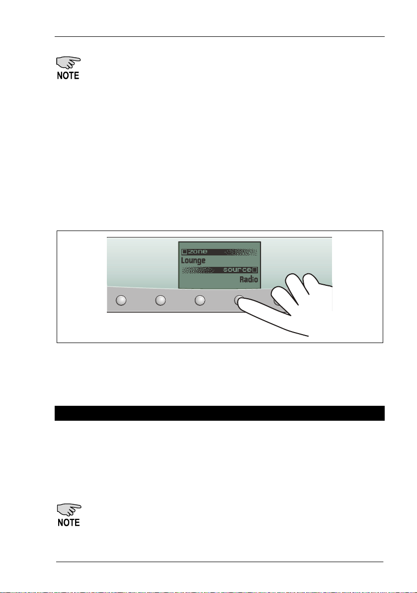
Pressing a Zone selection button displays the name and input source of
the zone (as shown in Figure 3). Pressing the button again within 8
seconds selects the next input source which is routed to the zone.
In a typical Multi Room Audio system installation, there are several ways
to change a zone’s input source. You can do this via:
• a Zone selection button on the Matrix Switcher
• the Source selection buttons on a Desktop Amplifier
• a remote control used with a Desktop Amplifier
• an appropriately configured C-Bus wall switch or touch screen.
234567
Figure 3 – In this example the Radio input is selected for the Lounge (zone 5)
4.0 Annunciation
The Matrix Switcher has the capability of announcing the name of an input
source whenever it is selected. This annunciation is broadcast through the
speakers in the zone where the input source has changed.
Annunciation provides instant feedback when changing the source
selection using a C-Bus switch, Amplifier or remote control.
The annunciation feature may be disabled by the installer (using
the MARPA configuration software).

Multi Room Audio Matrix Switcher
8
5.0 Rear Panel Connections
All connections to the Matrix Switcher are made via the rear panel.
Connectors and indicators are identified in Figure 4 and described in
Table 1.
Only use F 3,15AL 250V fuse
OPTICAL
OUT IN
ZONE8ZONE7ZONE6ZONE5ZONE4ZONE3ZONE2ZONE1
CAUTION: USE ONLY WITH C-Bus MULTIROOM AUDIO SYSTEM AMPLIFIERS
DIGITAL AUDIO OUT
DIGITAL
AUDIO
IN
SOURCE INPUT
1234L
R
BROADCAST USB
IR OUT
12
Unit
C-Bus
A
C power input
Power
switch Infrared outputs
Digital optical
output
Digital zone outputs
Digital optical
input
Mono broadcast
inputs
Stereo analo
g
ue inputs
Mono level
adjustment
C-Bus
USB
C-Bus
indicators
Digital audio input
Figure 4 – Matrix Switcher rear panel connectors and indicators
Connection
/Indicator
Description
Power switch Switches the mains power input on and off.
Mains power
input (IEC)
Connect mains here to power the Matrix Switcher.
Since the Matrix Switcher provides power to
connected Amplifiers, this connection also affects
Amplifiers which do not have an external power
supply.
Infrared outputs
(×2)
Use these 3.5 mm sockets to connect to IR Emitter
Leads. IR Emitters can be coupled to IR receivers on
equipment, providing remote control from any zone
through the Multi Room Audio system.

User’s Guide
9
Connection
/Indicator
Description
Mono broadcast
inputs (×2)
Line level mono audio connected here is broadcast
to all zones which have an analogue input source
selected.
There are two mono inputs with different priorities.
Audio connected to the LO input is transmitted by
Amplifiers at their current level.
Audio connected to the HI input is transmitted at a
preset level. Amplifiers which have a digital input
source selected, change to the fourth analogue
source so they can receive the high priority
broadcast audio.
Note: High priority (HI) broadcast audio uses left
channel speakers. Low priority (LO)
broadcast audio uses right channel speakers.
USB (Type B) This is used by the installer to configure the Matrix
Switcher.
C-Bus (×2) Connects to the C-Bus network.
Digital optical
output
Retransmits the data received by the digital optical
input.
Digital optical
input
Use this to connect a digital optical audio source to
be distributed to any of the eight zones. The digital
audio format must be 44.1 or 48 kHz stereo. Some
digital audio formats (such as surround sound) are
not compatible with the Matrix Switcher.
Digital zone
outputs (×8)
Each zone output is used to connect the Matrix
Switcher to one Amplifier in each zone. Additional
Amplifiers can be added to a zone by connecting
their Digital Audio In socket to the Digital Audio
Out of an existing Amplifier.
Digital audio
input
A Multi Room Audio Distribution Unit can be
connected to this input, providing an additional
stereo audio input.

Multi Room Audio Matrix Switcher
10
Connection
/Indicator
Description
Stereo analogue
inputs
(4× RCA pairs)
Connect up to four stereo analogue inputs to be
distributed to any of the eight zones.
Mono level
adjustment (×2)
These adjust the level of the audio source
connected to the mono broadcast inputs. Use a
small flat head screwdriver to rotate the control if
the audio source is too quiet or loud.
C-Bus indicators Unit
On: C-Bus network connected
Flashing: Data exchange in progress
C-Bus
On: C-Bus network operational
Off: Insufficient C-Bus power or clock
Flashing: Insufficient C-Bus power
Table 1 – Matrix Switcher connectors and indicators
6.0 Care Instructions
The Matrix Switcher contains electrical and electronic parts. Note the
following precautions:
• Clean using a soft lint free cloth.
• Do not use chemicals or spray cleaners when cleaning.
• Do not operate with wet hands.
• Do not use hard, sharp objects to select the controls.
• Allow adequate ventilation. Do not cover the unit.
• The Matrix Switcher is designed for indoor use only.
• Keep the unit away from water and other liquids.
• Do not expose the unit to high temperatures.

User’s Guide
11
6.1 Replacing the Fuse
The fuse is located next to the AC power socket on the rear of the Matrix
Switcher (as shown in Figure 5). To replace the fuse:
1) Switch the mains off at the power point. Unplug the power cord at
both ends (the power point and Matrix Switcher).
2) Insert your finger against the right edge of the socket and lift the
fuse compartment outwards.
3) Use a small instrument such as a screwdriver or pen. Insert the
instrument through the hole on the right hand side of the fuse
compartment, and push the fuse out.
4) Insert a replacement 3.15 A Fast Blow 20 × 5 mm fuse.
5) Close the fuse compartment by pushing it inwards.
Figure 5 – Replacing the fuse

Multi Room Audio Matrix Switcher
12
7.0 Broadcast Audio
The Matrix Switcher includes two broadcast inputs; 1 × high priority
(labelled HI) and 1 × low priority (labelled LO). These allow a mono input
such as a door bell, telephone extender or alarm to be broadcast
throughout the Multi Room Audio system.
Audio connected to the low priority input is broadcast at the currently set
volume, to all amplifiers which are switched on and have Source Input 1, 2,
3 or 4 selected.
Audio connected to the high priority input is broadcast to all amplifiers at
a volume set by the installer (using the MARPA configuration software).
Any Amplifiers which are in standby mode are switched on. All Amplifiers
that are not switched off temporarily change to Source Input 4 to ensure
the audio is broadcast as widely as possible. Five seconds after the
broadcast audio ceases, Amplifiers return to standby (if applicable) and to
their previously set volume.
These actions may vary depending on how the installer has configured the
Matrix Switcher.
Audio connected to a high priority broadcast input must be of
sufficient volume to trigger a broadcast.
A high priority (HI) broadcast uses left channel speakers. A low
priority (LO) broadcast uses right channel speakers.
NOTES

User’s Guide
13
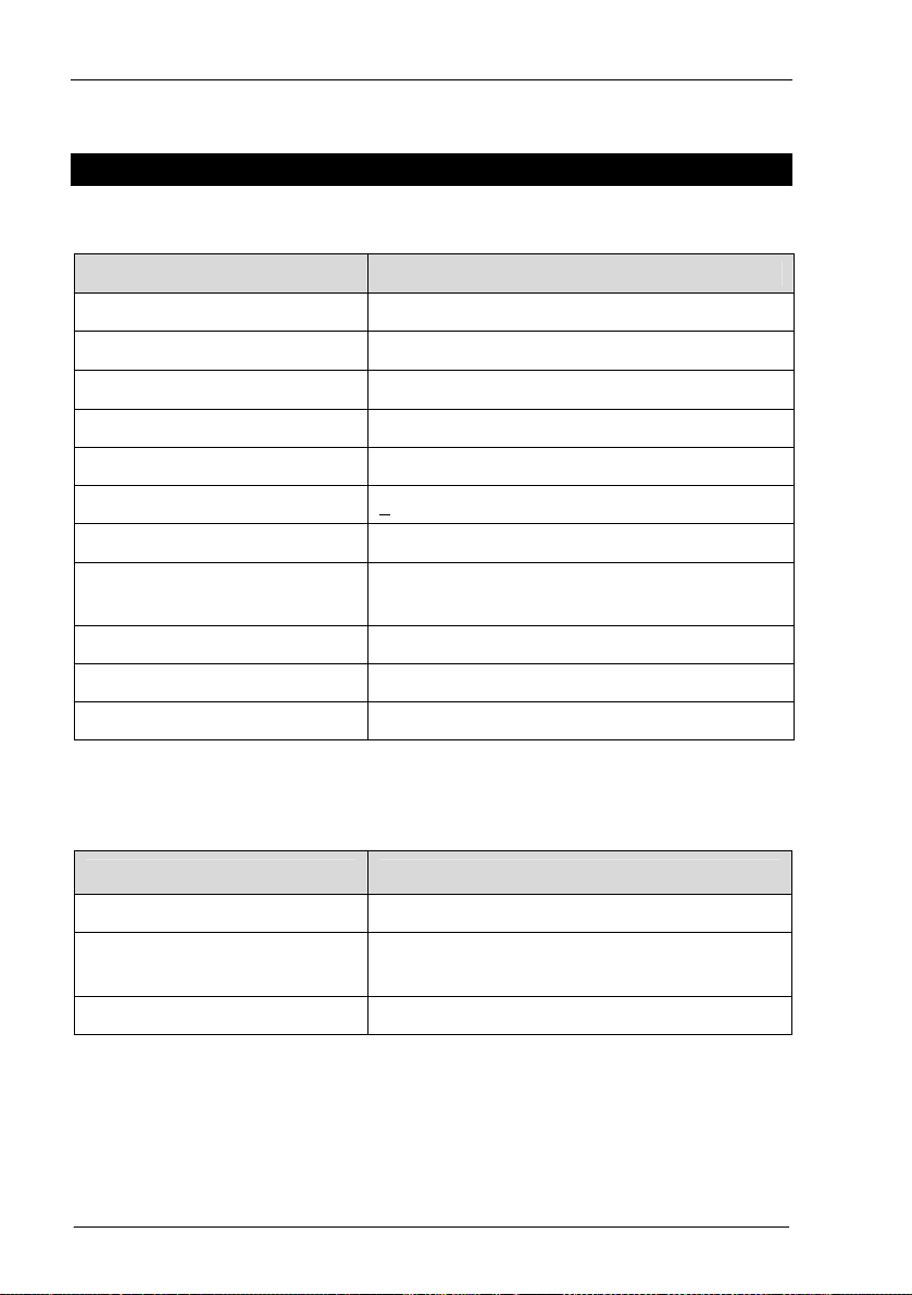
8.0 Troubleshooting
Symptom Possible Explanation
The Matrix Switcher no longer
responds to button presses.
Switch the Matrix Switcher off for
several seconds, then on. Use the
power switch on the rear of the Matrix
Switcher, next to the AC power socket.
Dynamic labels don’t work on
a C-Bus DLT wall switch.
There are several options which need
to be selected for labels to function.
These options are located:
• on the More panel accessed by
clicking the “More....” button on
the Amplifier’s C-Bus Control tab in
Toolkit
• on the DLT wall switch’s Global tab
in Toolkit
• on the Zones branch of the Project
tree in the MARPA software.
An Amplifier emits a high
pitched screeching sound
when a particular source is
selected.
This may occur if an output of an
Amplifier is connected to the input of
the Matrix Switcher. Such a connection
should be avoided as it can cause a
feedback loop.
The Matrix Switcher does not
power up.
The fuse may need replacing. Fuse
replacement is described on Page 11.
Audio is not broadcast via the
Matrix Switcher’s high priority
(HI) broadcast input.
The level of the audio connected to the
broadcast input may not be sufficient
to trigger the broadcast.
Cannot hear any sound when
using the optical input
The digital audio source may be
connected to the optical output instead
of the input. Some digital audio formats
(such as surround sound) are in-
compatible with the MRA system.
Multi Room Audio Matrix Switcher
14
9.0 Electrical Specifications
9.1 Matrix Switcher
Parameter Description
Supply voltage 240 V AC
Mains frequency range 47 to 53 Hz and 57 to 63 Hz
AC input impedance 47 kΩ
Power consumption 200 W maximum
C-Bus output voltage 36 V DC maximum
C-Bus output current < 330 mA
Network clock and burden Software selectable
Analogue input signal level
(Source inputs)
2.8 V p-p maximum (47 k Ω)
A/D conversion 16 bit PCM
Operating temperature 10 to 40 °C (50 to 104 °F)
Operating humidity 10 to 90% RH (non-condensing)
9.2 System Audio Performance
Parameter Matrix Switcher + Amplifier*
Frequency response 40 Hz to 20 kHz (+2.4/–0.75 db)
Total harmonic distortion
(1 kHz, 20 W RMS into 4 Ω)
0.16%
Signal to noise ratio > 63 dB (peak, unweighted)
* Analogue inputs of Matrix Switcher, measured from Amplifier speaker outputs

User’s Guide
15
10.0 Mechanical Specifications
12345678
ZONES
280.0 mm
424.3
mm
8.3 mm
66.1 mm
8.0 mm
346.
3
mm
228.9 mm 30.0 mm

Multi Room Audio Matrix Switcher
16
11.0 Standards Complied
DECLARATIONS OF CONFORMITY
Australian/New Zealand EMC & Electrical Safety Frameworks and Standards
The Multi Room Audio Matrix Switcher complies with the following:
Regulation Standard Title
Electrical Safety AS/NZS 60065 Audio, video and similar
electronic apparatus - Safety
requirements
EMC (C-Tick) AS/NZS CISPR 22 Information technology
equipment - Radio disturbance
characteristics (emissions)
12.0 Warranty
The Multi Room Audio Matrix Switcher carries a two year warranty against
manufacturing defects (refer to the Warranty Statement).

User’s Guide
17

Multi Room Audio Matrix Switcher
18


Technical Support and Troubleshooting
For further assistance in using this product, consult your nearest
Clipsal Integrated Systems (CIS) Sales Representative or Technical
Support Officer.
Technical Support Contact Numbers
Australia 1300 722 247 (CIS Technical Support Hotline)
New Zealand 0800 888 219 (CIS Technical Support Hotline)
A list of worldwide contacts, additional product information and
technical resources is provided at http://www.clipsal.com/cis/
Product of Clipsal Integrated Systems Pty Ltd
ABN 15 089 444 931
Head Office
12 Park Terrace, Bowden, SA 5007, Australia
Telephone: (+61) 8 8345 9500
Facsimile: (+61) 8 8346 0845
Web: http://www.clipsal.com/cis/ 1031974
Table of contents


