CLIVET HRV-2B-Mi Series User manual

M0H200002-00 - 06/21
HRV
HRV-2B-Mi D200÷D2000
MANUAL
FOR INSTALLATION,
USE AND MAINTENANCE

Directive 2002/96/EC (WEEE):
The symbol depicting a crossed-out waste bin that is underneath the appliance indicates
that this product, at the end of its useful life, must be handled separately from domestic
waste, must be taken to a recycling centre for electric and electronic devices or handed
back to the dealer when purchasing an equivalent appliance
WARNING
If the supply cord is damaged, it must be replaced by the manufacturer or its service agent
or a similarly qualified person in order to avoid a hazard.
An all-pole disconnection device which has at least 3mm separation distance in all pole and
a residual current device(RCD)with the rating of above 10mA shall be incorporated in the
fixed wiring according to the national rule.
Disconnect the power supply before cleaning and maintenance.
The appliance shall be installed in accordance with national wiring regulations.
This appliance can be used by children aged from 8 years and above and persons with
reduced physical, sensory or mental capabilities or lack of experience and knowledge if they
have been given supervision or instruction concerning use of the appliance in a safe way
and understand the hazards involved.
Children shall not play with the appliance.
Cleaning and user maintenance shall not be made by children without supervision.
DISPOSAL: Do not dispose this product as unsorted municipal waste.
Collection of such waste separately for special treatment is necessary.
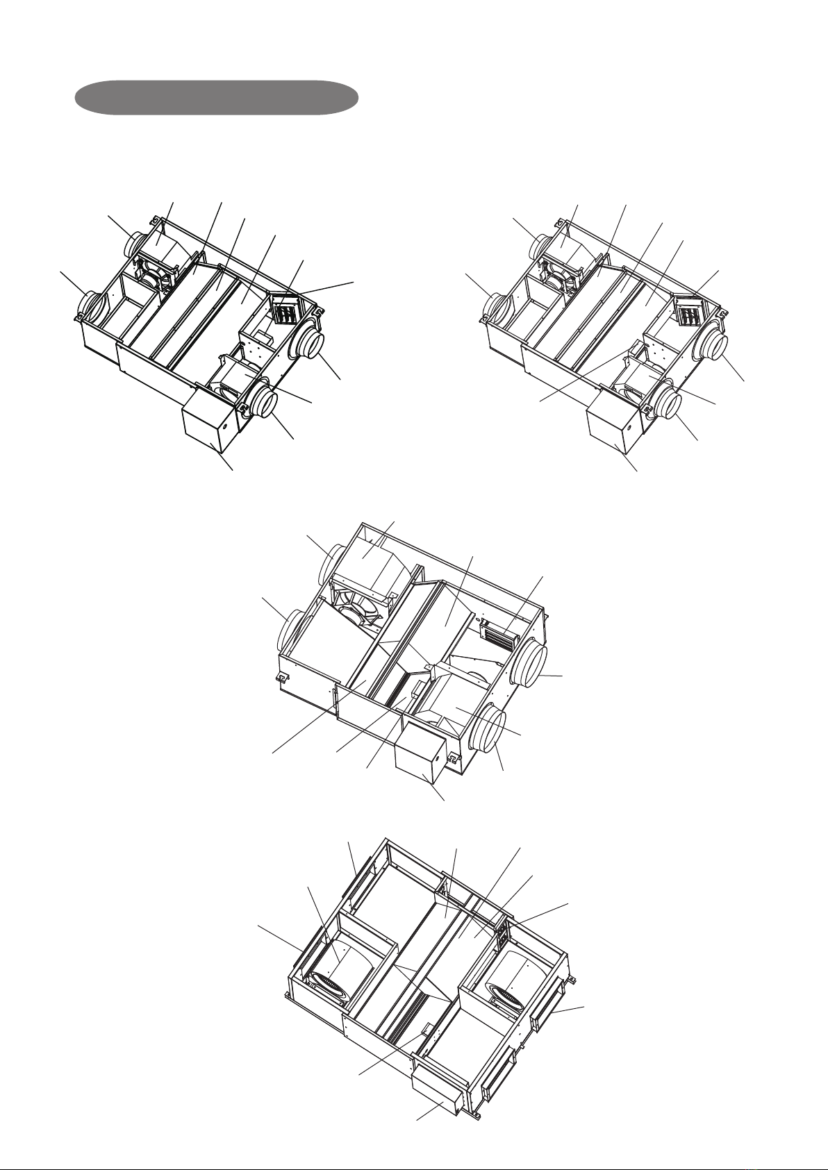
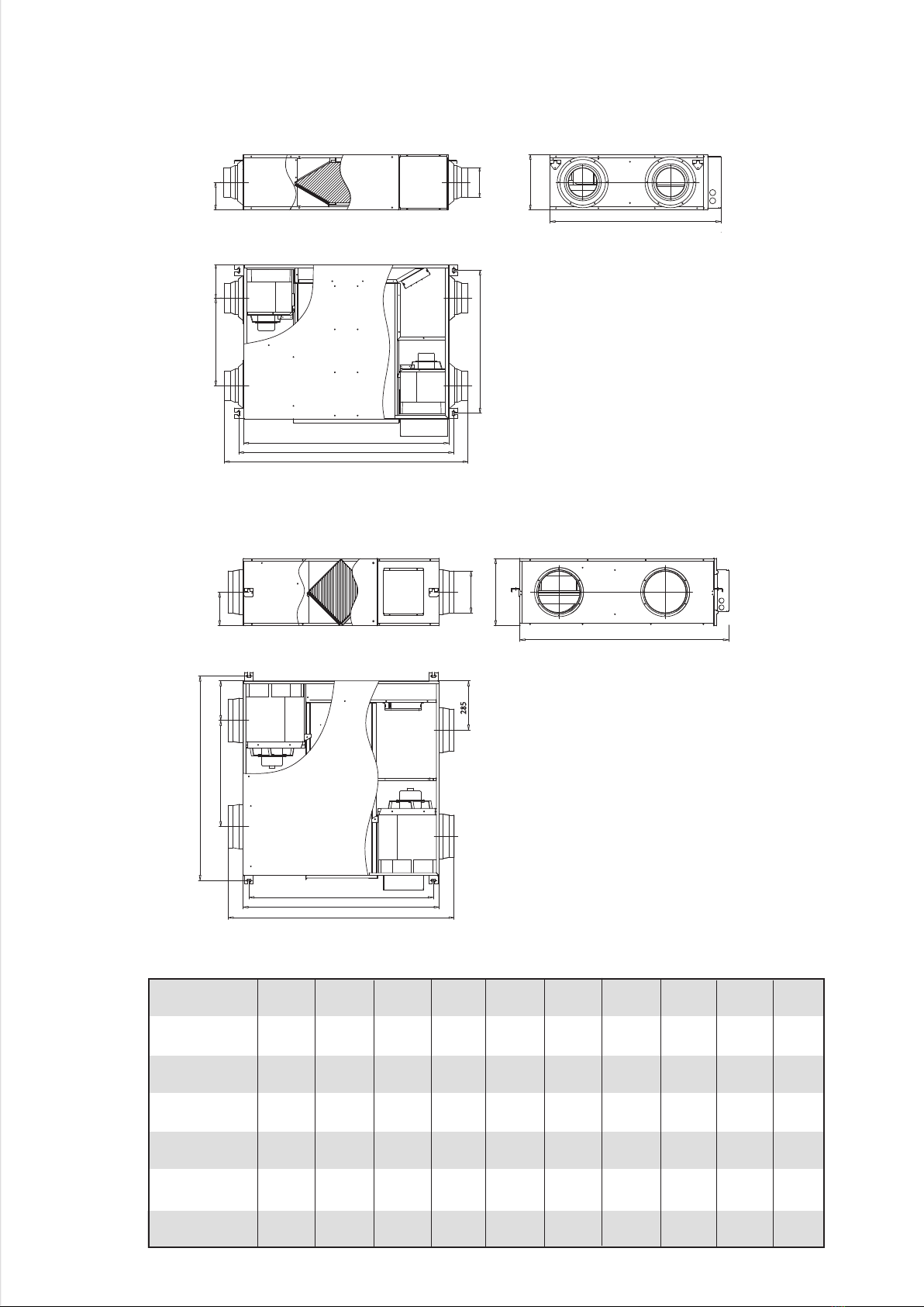
MAIN PARTS OF THE UNIT
HRV-2B-Mi D200~D300 HRV-2B-Mi D400
HRV-2B-Mi -D500~D1000
HRV-2B-Mi -D1500~D2000
Return air inlet
Supply air outlet
Electric control box
By-pass
CO2 sensor
Fan
Exaust air filter
Heat exchanger core
Fresh Air filter
Fan
Exhaust air outlet
Fresh air inlet
Return air inlet
Supply air outlet
Electric control box
By-pass
CO2 sensor Fan
Exaust Air filter
Heat exchanger core
Fresh Air filter
Fan
Exhaust air outlet
Fresh air inlet
Return air inlet
Fan
Supply air outlet
Electric control box
Fresh air inlet
Exhaust air outlet
CO2 sensor
Exaust Air filter
Heat exchanger core
By-pass
Fan
Fresh Air filter
Exhaust air outlet
Return air inlet
Fan
Supply air outlet
Exaust Air filter
Fresh Air filter
By-pass
Heat exchanger core
Electric control box
CO2 sensor
1. PRECAUTIONS
To prevent injury to the user or other people and property
damage, the following instructions must be followed. Incorrect
operation due to ignoring of instructions may cause harm or
damage. The appliance should be installed by a professional
in accordance with the specified instructions.
CAUTION
WARNING
WARNING
Failure to observe a warning may cause electric shock,
fire hazard or personal injury
CAUTION
CONTENTS PAGE
PRECAUTIONS........................................................................................
ACCESSORY...........................................................................................
INSTALLATION........................................................................................
WIRING...................................................................................................
SPECIFICATION PARAMETER................................................................
HRV APPLICATION................................................................................
MAINTENANCE AND UPKEEP....................................................................
TRAIL RUN.............................................................................................
ERP INFORMATION..............................................................................
1
1
2
6
8
9
9
9
10
The safety precautions listed here are divided into two categories. In
either case, important safety informations are listed which must be
read carefully.
Failure to observe a caution may cause injury or damage
to the equipment.
● Ask your dealer or qualified personnel to carry out
installation work. Do not try to install the machine by.
Incorrect installation may result in leakage, electric shocks
or fire.
● Installation should be done by following the installation
manual and no changes should be made to the unit.
Incorrect installation may cause leakage, electric shock, or
fire. If the HRV falls, it may cause damage and injury.
● Install the unit on a foundation that is strong enough to
withstand the weight of the unit.
A foundation of insufficient strength may result in the
equipment falling and causing injuries.
● Do not allow exhaust air to enter the outside air inlet.
This may cause the air of the room to become contaminated
, harming the health.
● Locate the outside air intake vent so that it does not take in
exhaust air which contains combustion air, etc.
Incorrect installation may cause a loss of oxygen in the
room, leading to serious accidents.
● Make sure that a separate power supply circuit is provided
for this unit and that all electrical work is carried out by
qualified personnel according to local laws and regulations
and this installation manual.
Insufficient power capacity, improper electrical works, or
incorrect wiring may cause electric shock or fire.
● Make sure Earth Leakage Breaker is the type of all poles drop-out.
● Be sure to ground.
Do not connect the ground wire to gas or water pipes, lightning rod
or a telephone ground wire.
Incomplete grounding may result in electric shocks.
● Make sure that all wiring is secured, the specified wires are used,
and no external forces act on the terminal connections or wires.
Improper connections or installation may result in overheating or
fore.
● When wiring the power supply and connecting the remote
controller wiring and transmission wiring, position the wires so that
the electric parts box lid can be securely fastened.
Improper positioning of the electric parts box lid may result in
electric shocks, fire or the terminals overheating.
● Be sure to install an earth leakage breaker.
Failure to install an earth leakage breaker may result in
electric shocks.
● Install the indoor and outdoor units, power supply wiring and
connecting wires at least 1 meter away from television or
radio in order to prevent image interference or noise.
(Depending on the radio waves, a distance of 1 meter may not
be sufficient enough to eliminate the noise.)
● Install the two outdoor ducts with down slope to prevent
rainwater from entering the unit.
If this is not done completely, water may enter the building,
may damage furniture, etc.
● Insulate the duct and the wall electrically when a metal duct is
to be penetrated through the metal lattice and wire lattice or
metal lining of a wooden structure wall.
Improper duct work may cause electric shocks or short
circuits.
● Make sure that a snow protection measure is taken. If no
protection snow may enter through the outdoor ducts, and
cause damaging furniture and electric shock and fire.
2. ACCESSORY
Name Qty. Shape Purpose
This
manual
must be delivered to the
customer
Installation
and owner’s
manual
1
Name
PVC drain pipe
Damper
Purpose
Table 2-1
For connecting unit’s drain pipe, which length
is selected according to your actual
requirement (Only required for Model 1500
and 2000
For vibration damping, when lift the unit.
Prepare the following on site.
Table 2-2
Notes:Wired controller should be purchased separately.
1
3. INSTALLATION
3.1 Installation Preparation
WARNING
Keep all the accessories and tools until installation work is
completed.
● Leave the unit inside its packaging while moving, until
reaching the installation site. Where unpacking is
unavoidable, use a sling of soft material or protective
plates together with a rope when lifting, to avoid damage
or scratches to the unit.
● Hold the unit by the hanger brackets when opening the
crate and moving it, and do not lift it holding on to any
other part (especially the duct connecting flange).
NOTE
Be sure to instruct customers how to properly operate the unit
(especially maintenance of air filter, and operation procedure)
by having them carry out operations themselves while looking
at the manual.
3.2 Select The Installation Site
CAUTION
When moving the unit during or after unpacking, make sure to
lift it by holding its hanger brackets. Do not exert any pressure
on other parts, especially duct connecting flange.
● Select an installation site where the following conditions
are fulfilled and meet with your customer’s approval.
HRV should be installed far away from office, recreation
or any other places where silent environment are
required. (install that in special machine room or wash
room is recommended)
install in a place which has sufficient strength and
stability. (Beam, ceiling and other locations capable of
fully supporting the weight of the unit.) Insufficient
strength is dangerous. It may also cause vibration and
unusual operating noise.
Do not install the unit directly against a ceiling or wall. (If
the unit is in contact with the ceiling or wall, it can cause
vibration.)
Where sufficient clearance for maintenance and service
can be ensured.
CAUTION
● Install the units, power supply wiring and connecting wires
at least 1 meter away from televisions or radios in order to
prevent interference or noise. (Depending on the
radio waves, a distance of 1 meter may not be sufficient
enough to eliminate the electric interference.)
● The bellows may not be able to be used in some districts,
so exercise caution. contact your local government office
or fire department for details.
● When discharging exhaust air to a common duct, the
Building Standard Law requires the use of fire proof
materials, so attach a 2m copper plate standing duct.
● Do not install the unit in the following locations:
● Place subjected to high temperature or direct flame. May
result in fire or overheating.
● Place such as machinery plant and chemical plate where
gas, which contains noxious gas or corrosive components
of materials such as acid, alkali organic solvent and plaint,
is generated. Place where combus tible gas leakage is
likely.
Copper piping and brazed joins may corrode, causing
refrigerant to leak or poisoning and fore due to leaked gas.
● Place such as bathroom subjected to moisture.
Electric leak or electric shocks and other failure can be
caused.
● Near machinery emitting electromagnetic waves.
Electromagnetic waves may disturb the operation of the
control system and result in a malfunction of the
equipment.
3.3 Preparations Before Installation
Confirm the positional relationship between the unit and
suspension bolts.
Leave space for servicing the unit and include
inspection hatches. (Always open a hole on the side of
the electric parts box so that the air filters, heat
exchange elements, fans, be easily be inspected and
serviced.)
Make sure the range of the unit’s external static
pressure is not exceeded.
Open the installation hole (Pre-setting ceilings)
Once the installation hole is opened in the ceiling where
the unit is to be installed, pass transmission wiring, and
remote controller wiring to the unit’s wiring holes.
After opening the ceiling hole, make sure ceiling is level
if needed. It might be necessary to reinforce the ceiling
frame to prevent shaking.
Please consult architect or woodworker, if necessary.
Install the suspension bolts. (Use M10 to M12
suspension bolts.) Use a hole-in anchor, sunken insert
anchor for existing ceilings, or other parts to be
procures in the field to reinforce the ceiling to bearing
the weight of the unit.
Install vibration damping feet. (For vibration damping)
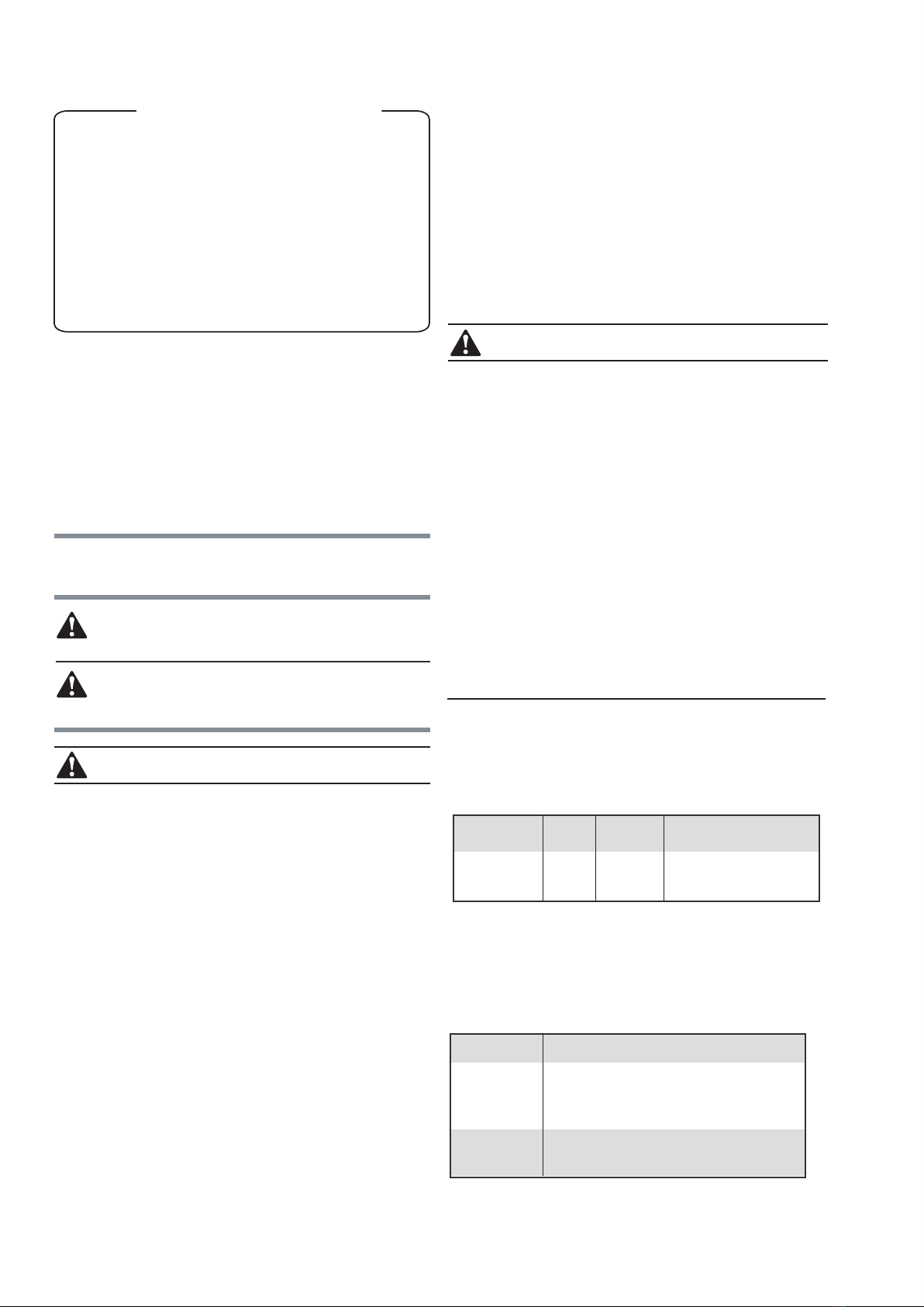
Wooden structure
Put rectangular sticks across the beams, and set pendant bolts.
Wooden span
Beam
Ceiling
Pendant bolt(M10 to M12)
Old concrete roughcast
Use embedded bolts and embedded pulling plugs.
Fig. 3-1
●
●
●
●
●
●
●
●
●
2
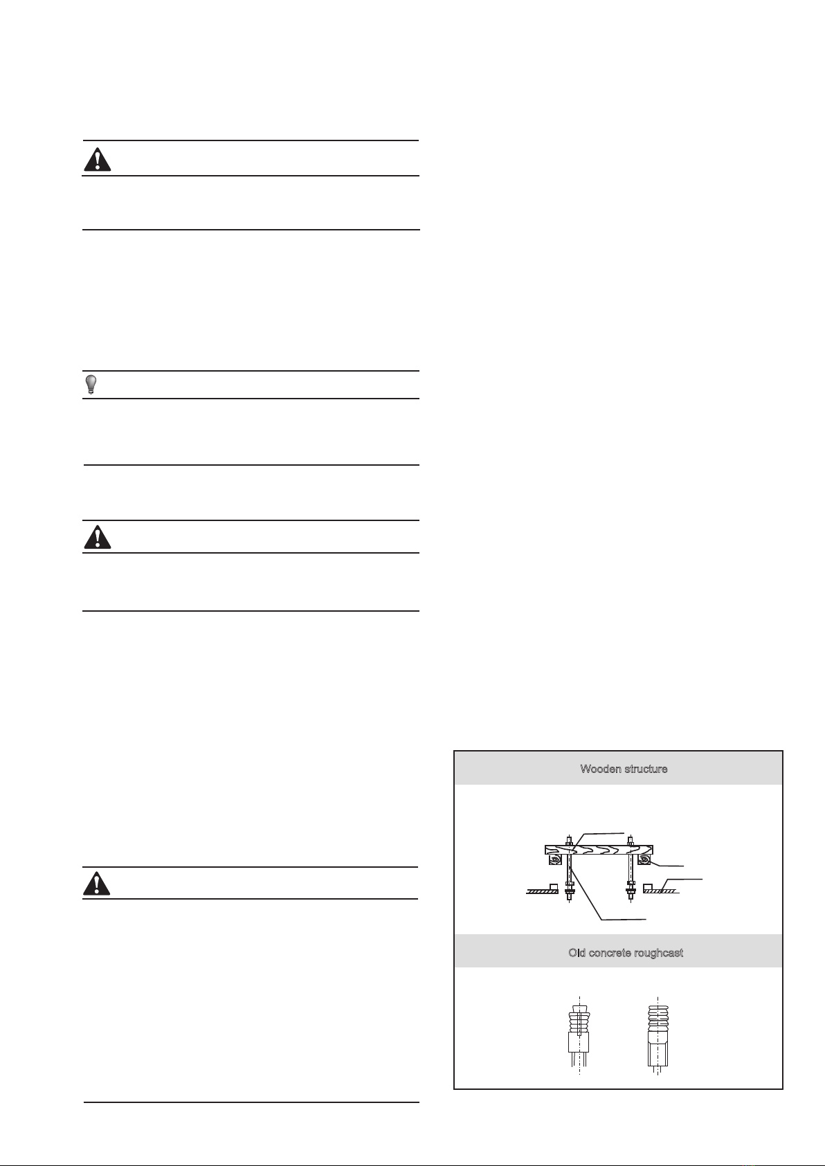
Set and use supportive angle steel.
Steel beam and girder structure
Suspended bolt
Pendant bolt Supportive angle steel
Set it with embedded bushes or embedded bolts.
New concrete roughcast
Flap type inser Slide type inser
Concrete iron
Embedded bolt
(With embedded
bolt in pipe)
Fig. 3-2
3.4 Installation
Before installation, please confirm all external parts are
stand in their place and without damage.
The surrounding environment of the unit, especially the
sides of wiring cabinet and water collecting side should
reserve sufficient wiring and maintenance and space;
additionally, one should ensure the removing space for
filter griller.
Unit should mount steadily and without sustain the weight
form condensate water pipe and air duct. The vents of air
inlet/outlet and return should be connected with flexible
tube.
Unit in AC 220-240V/50Hz, reliable grounding; each one
possesses of independent cut-off and protection device.
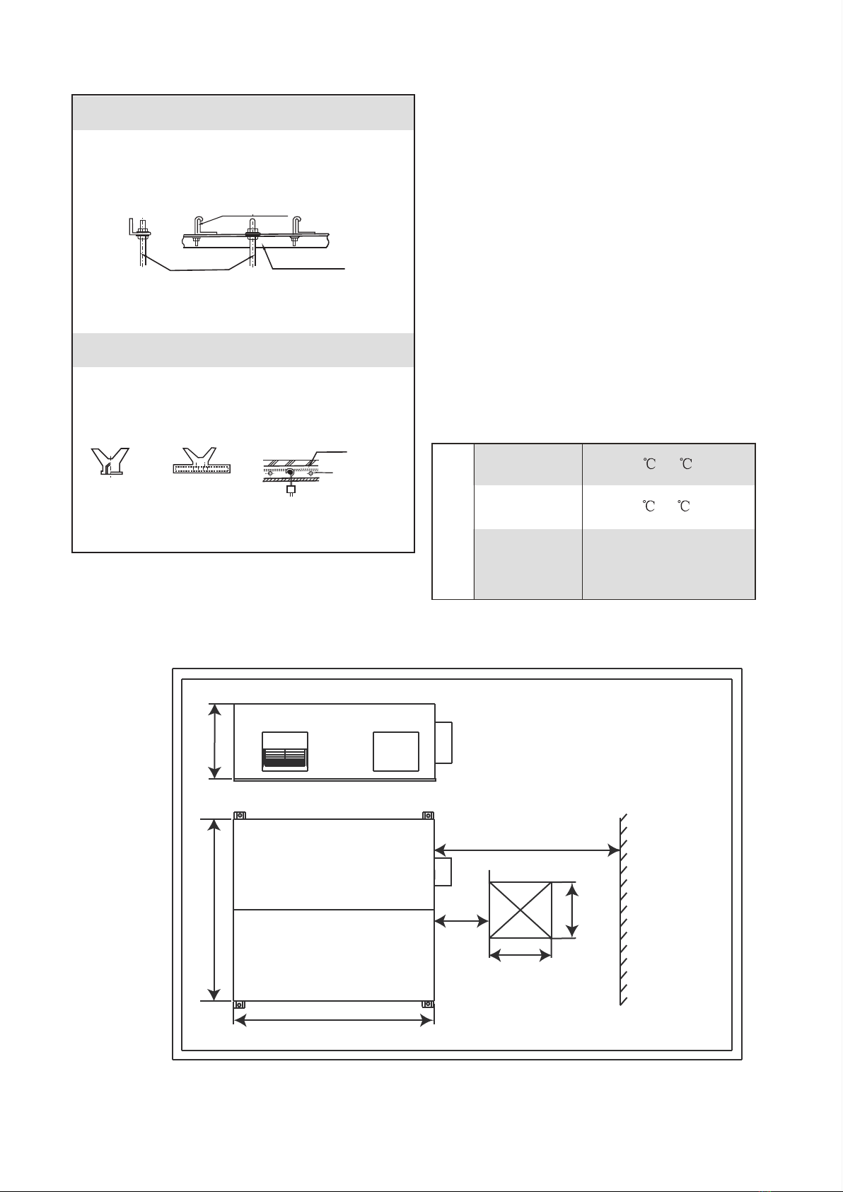
The installation dimension and maintenance space. (See
the following attached picture Fig.3-3 )
Unit:mm
Operating conditions
For proper performance, run the air conditioner under the
following temperature conditions:
Outdoor air TEMP
.
Room TEMP.
Room humidity
-7 ~43
0 ~43
Lower than 80%
If higher than 80%, the surface of
indoor unit may be condensed or
the condensate will be blown from
air outlet.
Protection or error may occur if running the unit beyond the above
condition, and will cause unit stop running.
OPERATION
●
●
●
●
●
●
H
450
054
1000
400
Maintenance space
L
W
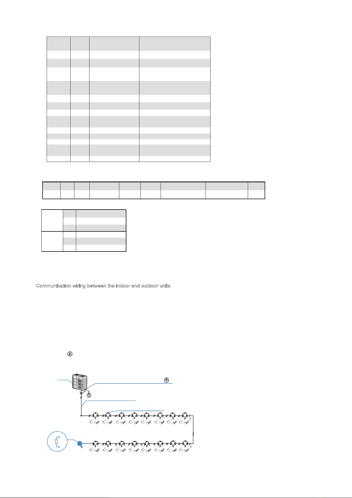
Communication wiring between the indoor and outdoor units
The HRV and outdoor units communicate via the RS485 serial port.
The communication wiring between the HRV and outdoor units should be connected one unit after
another in a daisy chain from the outdoor unit to the final HRV unit. And the shielded layer must be
properly grounded, and a build-out resistor must be added to the last HRV unit to enhance the stability
of the communication system.
Incorrect wiring such as a star connection or a closed ring will cause instability of the communication
system and system control anomalies.
Use a three core shielded wire (greater than or equal to 0.75 mm2) for the communication wiring
between the indoor and outdoor units. Make sure the wiring is connected correctly. The connecting lead
for this communication wire must come from the master outdoor unit.
All shielded wiring in the network are interconnected, and will eventually connect to earth at the same
point " ”.
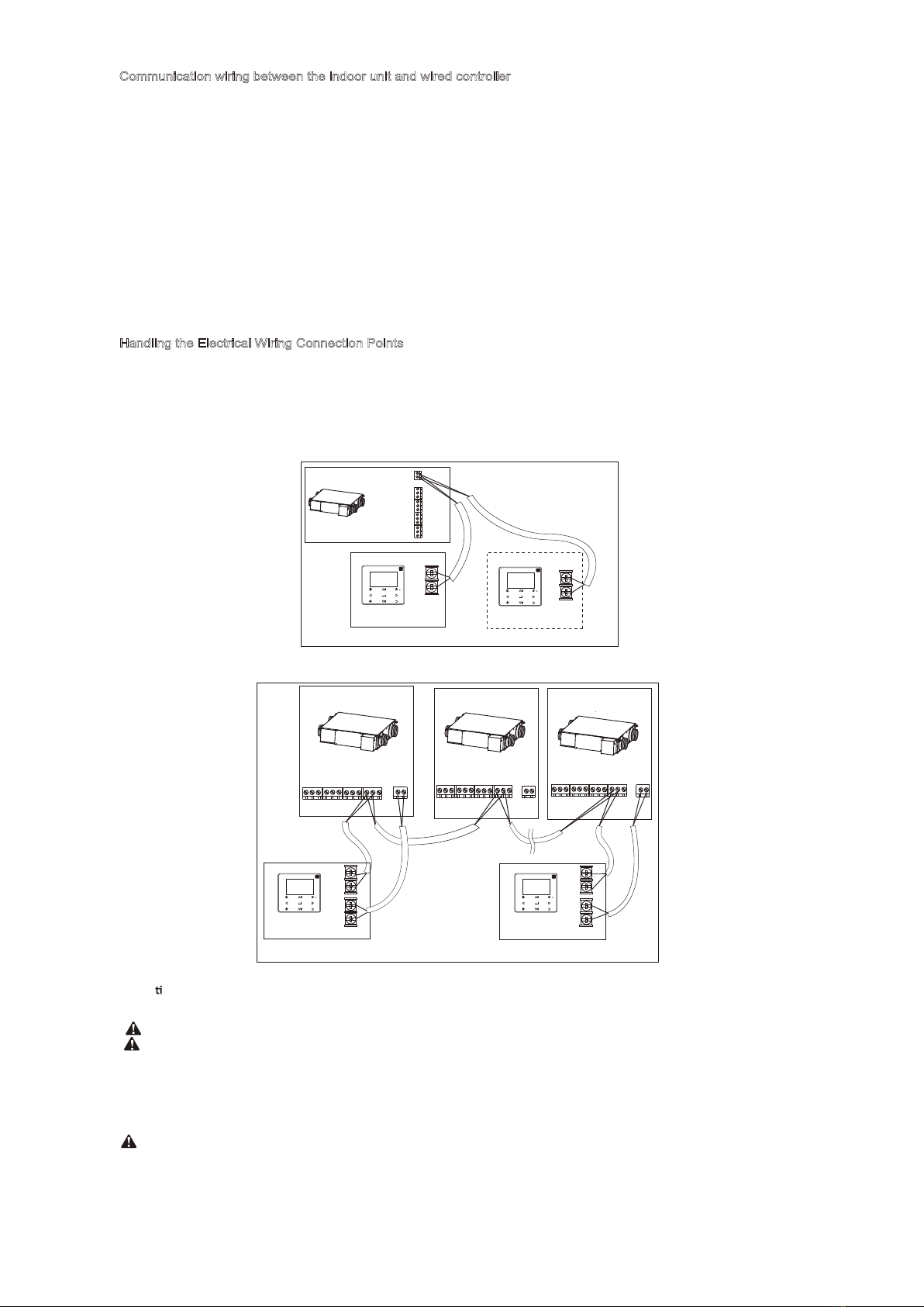
Communication wiring between the indoor unit and wired controller
The wired controller and the indoor unit can be connected in different manners, depending on the forms of
communication.
1. For a bidirectional communication mode:
Use 1 wired controller to control 1 indoor unit or 2 wired controllers (one master and one slave
controller) to control 1 indoor unit.(see Fig.4-4)
Use 1 wired controller to control multiple indoor units or 2 wired controllers (one master and one slave
controller) to control multiple indoor units. The maximum number of connections is 16.(see Fig.4-5)
2. For single direction communication mode:
Use 1 wired controller to control 1 indoor unit
The X1/X2, D1/D2 ports on the sides of the main control board and single direction communication port
are for different types of wired controllers.
For the specific connection method, refer to the instructions in the corresponding wired controller
manual to carry out the wiring and connections.
Handling the Electrical Wiring Connection Points
Once the wiring and connections are done, use tie straps to secure the wiring properly so that the
connection joint cannot be pulled apart by external force. The connection wiring must be straight out so
that the cover of the electrical box is level and can be closed tightly.
Use professional insulation and sealing materials to seal and protect the perforated wires. Poor sealing
may lead to condensation, and entry of small animals and insects that may cause short circuits in parts
of the electrical system, causing the system to fail.
multiple indoor units (see Figure 7.8);
3
L L1 L2 W1 W2 W H H1 N
1007
1007
1081
1071
1071
1054
1054
1129
1138
1138
1195
1195
1276
1311
1311
588
701
991
1005
1185
356
431
595
465
616
801
914
1204
1106
1286
272
272
272
390
390
142
163
202
227
229
Φ144
Φ144
Φ198
Φ244
Φ244
N1
136
136
136
195
195
Fig. 3-4
Fig. 3-5
Table 3-1
Key dimensions of the unit and air duct installation. (See the following pictures Fig.3-4~3-7 & Table 3-1 )
Door
Electric
control
box
By-pass
system
Exhaust air outlet
Fresh air inlet
Return air inlet
Supply air outlet
Lifting lug
N
N1
H
W
W1
L
L1
L2
W2
H1
L1
L
L2
N1
N
W
Door
Electric
control
box
Return air inlet
Supply air outlet
Exhaust air outlet
Fresh air inlet
H1
W2
W1
H
195
Φ244230
390
1526
7641431
1138 1311
1071
Communication wiring between the indoor and outdoor units
The HRV and outdoor units communicate via the RS485 serial port.
The communication wiring between the HRV and outdoor units should be connected one unit after
another in a daisy chain from the outdoor unit to the final HRV unit. And the shielded layer must be
properly grounded, and a build-out resistor must be added to the last HRV unit to enhance the stability
of the communication system.
Incorrect wiring such as a star connection or a closed ring will cause instability of the communication
system and system control anomalies.
Use a three core shielded wire (greater than or equal to 0.75 mm2) for the communication wiring
between the indoor and outdoor units. Make sure the wiring is connected correctly. The connecting lead
for this communication wire must come from the master outdoor unit.
All shielded wiring in the network are interconnected, and will eventually connect to earth at the same
point " ”.
By-pass
system
(Unit:mm)
Communication wiring between the indoor unit and wired controller
The wired controller and the indoor unit can be connected in different manners, depending on the forms of
communication.
1. For a bidirectional communication mode:
Use 1 wired controller to control 1 indoor unit or 2 wired controllers (one master and one slave
controller) to control 1 indoor unit.(see Fig.4-4)
Use 1 wired controller to control multiple indoor units or 2 wired controllers (one master and one slave
controller) to control multiple indoor units. The maximum number of connections is 16.(see Fig.4-5)
2. For single direction communication mode:
Use 1 wired controller to control 1 indoor unit
The X1/X2, D1/D2 ports on the sides of the main control board and single direction communication port
are for different types of wired controllers.
For the specific connection method, refer to the instructions in the corresponding wired controller
manual to carry out the wiring and connections.
Handling the Electrical Wiring Connection Points
Once the wiring and connections are done, use tie straps to secure the wiring properly so that the
connection joint cannot be pulled apart by external force. The connection wiring must be straight out so
that the cover of the electrical box is level and can be closed tightly.
Use professional insulation and sealing materials to seal and protect the perforated wires. Poor sealing
may lead to condensation, and entry of small animals and insects that may cause short circuits in parts
of the electrical system, causing the system to fail.
Model
4
HRV-2B-Mi D200~D400
HRV-2B-Mi -D500~D1000
HRV-2B-Mi -D200
HRV-2B-Mi -D300
HRV-2B-Mi -D400
HRV-2B-Mi -D500
HRV-2B-Mi -D800
HRV-2B-Mi -D1000

Fig. 3-6
Fig. 3-7
615
252
320
320
300
300
60
1425
650
1690
1740
1300
1270
Door
Electric
control
box
Supply air outlet
Exhaust air
outlet
Return air inlet
Fresh air
inlet 120
320
346
370
350
326
300
Flange dimension
320
300
320
750
1625
60
685
252
300
1470
1500
1761
1811
120
320
346
370
350
326
300
Flange dimension
Supply air outlet
Exhaust air
outlet
Fresh air inlet
Door
Communication wiring between the indoor and outdoor units
The HRV and outdoor units communicate via the RS485 serial port.
The communication wiring between the HRV and outdoor units should be connected one unit after
another in a daisy chain from the outdoor unit to the final HRV unit. And the shielded layer must be
properly grounded, and a build-out resistor must be added to the last HRV unit to enhance the stability
of the communication system.
Incorrect wiring such as a star connection or a closed ring will cause instability of the communication
system and system control anomalies.
Use a three core shielded wire (greater than or equal to 0.75 mm2) for the communication wiring
between the indoor and outdoor units. Make sure the wiring is connected correctly. The connecting lead
for this communication wire must come from the master outdoor unit.
All shielded wiring in the network are interconnected, and will eventually connect to earth at the same
point " ”.
Electric
control
box
Return air inlet
By-pass
system
Communication wiring between the indoor unit and wired controller
The wired controller and the indoor unit can be connected in different manners, depending on the forms of
communication.
1. For a bidirectional communication mode:
Use 1 wired controller to control 1 indoor unit or 2 wired controllers (one master and one slave
controller) to control 1 indoor unit.(see Fig.4-4)
Use 1 wired controller to control multiple indoor units or 2 wired controllers (one master and one slave
controller) to control multiple indoor units. The maximum number of connections is 16.(see Fig.4-5)
2. For single direction communication mode:
Use 1 wired controller to control 1 indoor unit
The X1/X2, D1/D2 ports on the sides of the main control board and single direction communication port
are for different types of wired controllers.
For the specific connection method, refer to the instructions in the corresponding wired controller
manual to carry out the wiring and connections.
Handling the Electrical Wiring Connection Points
Once the wiring and connections are done, use tie straps to secure the wiring properly so that the
connection joint cannot be pulled apart by external force. The connection wiring must be straight out so
that the cover of the electrical box is level and can be closed tightly.
Use professional insulation and sealing materials to seal and protect the perforated wires. Poor sealing
may lead to condensation, and entry of small animals and insects that may cause short circuits in parts
of the electrical system, causing the system to fail.
5
HRV-2B-Mi -D1500
HRV-2B-Mi -D2000
4. WIRING
220-240V/50Hz
see 10. Electrical
Characteristics table
2.5
4.1 Electric data Specification
Table 4-1
Power supply
Phase
Voltage
/frequency
Input current
Main switch
/fuse(A)
Power supply
wireDimension
Wire’s qty
Wire
cross
-section
(mm
2
)
3 (Earthing line
should be used
yellow/green wire.)
Single phase
All the supplied parts, materials and electrical works must
comply with local regulations.
Only use copper wires.
Use a steady power supply for the air-conditioners. The
power voltage must be in line with the rated voltage.
The electrical wiring works must be carried out by a
professional technician, and must comply with the labels stated
in the circuit diagram.
Before the electrical connection works are carried out, turn
off the power supply to prevent injuries caused by electric
shock.
The external power supply circuit of the air conditioner must
include an earth line, and the earth line of the power cord
connecting to the indoor unit must be securely connected to
the earth line of the external power supply.
Leakage protective devices must be configured according to the
local technical standards and requirements for electrical and
electronic devices.
The fixed wiring connected must be equipped with an all-pole
disconnection device with a minimum 3 mm contact
separation.
The distance between the power cord and signal line must be
at least 300 mm to prevent the occurrences of electrical
interference, malfunction or damage to electrical
components. At the same time, these line must not be in
contact with the piping and valves.
Choose electrical wiring that conforms to the corresponding
electrical requirements.
Connect to the power supply only after all the wiring and
connections have been completed, and check carefully if the
connection is correct.
Warning
Communication wiring between the indoor and outdoor units
The HRV and outdoor units communicate via the RS485 serial port.
The communication wiring between the HRV and outdoor units should be connected one unit after
another in a daisy chain from the outdoor unit to the final HRV unit. And the shielded layer must be
properly grounded, and a build-out resistor must be added to the last HRV unit to enhance the stability
of the communication system.
Incorrect wiring such as a star connection or a closed ring will cause instability of the communication
system and system control anomalies.
Use a three core shielded wire (greater than or equal to 0.75 mm2) for the communication wiring
between the indoor and outdoor units. Make sure the wiring is connected correctly. The connecting lead
for this communication wire must come from the master outdoor unit.
All shielded wiring in the network are interconnected, and will eventually connect to earth at the same
point " ”.
POWER INPUT
L
N
figure of the power supply terminal
+Power
cord
Insulation tube
Circular wiring
terminal
: Copper wire
Proper power wiring connections
When connecting to the power supply terminal, use the circular wiring
terminal with insulation.
Use power cord that conforms to the specifications and connect the
power cord firmly. To prevent the cord from being pulled out by
external force, make sure it is fixed securely.
If circular wiring terminal with insulation cannot be used, please make
sure that:
• Do not connect two power cords with different diameters to the
same power supply terminal (may cause overheating).
Fig. 4-1
Fig. 4-2 Fig. 4-3
ENC1 Settings for Capacity SW1 Setting for static pressure
• Positive Pressure: In the positive pressure mode, the supply fan
operating fan speed is higher than the exhaust fan.
• Negative Pressure: In the negative pressure mode, the exhaust fan
operating fan speed is higher than the supply fan.
• Balance Pressure: In the balance pressure mode, the supply fan
operating wind gear is equal to the exhaust fan.
Caution
Table 4-2
5
3
2
1
4
ENC1 Capacity sett ing
0
6
7
200
300
400
500
800
1000
1500
2000
Communication wiring between the indoor unit and wired controller
The wired controller and the indoor unit can be connected in different manners, depending on the forms of
communication.
1. For a bidirectional communication mode:
Use 1 wired controller to control 1 indoor unit or 2 wired controllers (one master and one slave
controller) to control 1 indoor unit.(see Fig.4-4)
Use 1 wired controller to control multiple indoor units or 2 wired controllers (one master and one slave
controller) to control multiple indoor units. The maximum number of connections is 16.(see Fig.4-5)
2. For single direction communication mode:
Use 1 wired controller to control 1 indoor unit
The X1/X2, D1/D2 ports on the sides of the main control board and single direction communication port
are for different types of wired controllers.
For the specific connection method, refer to the instructions in the corresponding wired controller
manual to carry out the wiring and connections.
Handling the Electrical Wiring Connection Points
Once the wiring and connections are done, use tie straps to secure the wiring properly so that the
connection joint cannot be pulled apart by external force. The connection wiring must be straight out so
that the cover of the electrical box is level and can be closed tightly.
Use professional insulation and sealing materials to seal and protect the perforated wires. Poor sealing
may lead to condensation, and entry of small animals and insects that may cause short circuits in parts
of the electrical system, causing the system to fail.
SW1-1
SW1-2
SW2-1
SW2-2
SW2-3
ON
OFF
ON
OFF
ON
OFF
ON
ON
OFF
OFF
HRV centralized control
HRV single unit operation
With PRO (reserved)
Without PRO (reserved)
Positive Pressure
Negative Pressure
SW2-2
Balance Pressure
1 2
ON
1 2
ON
3
1 2
ON
3
1 2
ON
3
1 3
ON
2
1 2
ON
3
1 2
ON
3
1 2
ON
1 2
ON
1 2
ON
Low static pressure
High static pressure
● After wiring, please confirm all connections are correct,
and then power to the unit.
● Pay attention to the power supply wire of three-phase
model; confirm the phase sequence of which is correct.
6
HRV-2B-Mi -D200~ D2000
Communication wiring between the indoor and outdoor units
The HRV and outdoor units communicate via the RS485 serial port.
The communication wiring between the HRV and outdoor units should be connected one unit after
another in a daisy chain from the outdoor unit to the final HRV unit. And the shielded layer must be
properly grounded, and a build-out resistor must be added to the last HRV unit to enhance the stability
of the communication system.
Incorrect wiring such as a star connection or a closed ring will cause instability of the communication
system and system control anomalies.
Use a three core shielded wire (greater than or equal to 0.75 mm2) for the communication wiring
between the indoor and outdoor units. Make sure the wiring is connected correctly. The connecting lead
for this communication wire must come from the master outdoor unit.
All shielded wiring in the network are interconnected, and will eventually connect to earth at the same
point " ”.
Terminal Definition
Table 4-4
Code and Definitions
Table 4-3
Show on
centralized controller
Unit is ON
Unit is OFF
Operation
lamp
Indoor temperature
sensor error
Outdoor temperature
sensor error
EEPROM error
DC fan motor error
Explanation
○
●
★
★
★
★
★
★
/ /
//
E2
4
E5(new protocol)
EF(old protocol)
6 E7
8 E6
10 OFF LINE Without address
Communication error
with ODU
12 E1
NOTE:
●:Light ; ○:Extinguish ; ★:Quick flash
Flashing
times
★
★
★
14
16
18
E9
EU
FC
error with sensor board
error with CO2 sensor
wire controller
communication failure
Ip address Conflict
Ed Outdoor unit failure
reserved
Dry contact
(Out put)
Dry contact
(In put)
CN31
CN16
CN26
CN14
CN15
CN20
Remote ON/OFF
Force to exhaust air mode
Signal for inlet air Pre-heat
Alarm
Reserved
CODE
NAME Outdoor temp. SensorP Q E X Y E X1X2
CN8 CN9 CN32 CN33
- D1D2E
CN7 CN3 CN4
Indoor temp. Sensor
CN21
-
(P Q E)
(P Q E)
Only the last indoor unit requires adding
the build-out resistor at P and Q.
(open)
Indoor and
outdoor units
Communication wire
Connecting the shielded
layer of the shielded wire
(Connect the shielded end of the shielded wire to the
electronic controller box sheet metal " " here)
Signalling line
between outdoor units
Outdoor
unit
P
Q
Build-out
resistor
Communication wiring between the indoor unit and wired controller
The wired controller and the indoor unit can be connected in different manners, depending on the forms of
communication.
1. For a bidirectional communication mode:
Use 1 wired controller to control 1 indoor unit or 2 wired controllers (one master and one slave
controller) to control 1 indoor unit.(see Fig.4-4)
Use 1 wired controller to control multiple indoor units or 2 wired controllers (one master and one slave
controller) to control multiple indoor units. The maximum number of connections is 16.(see Fig.4-5)
2. For single direction communication mode:
Use 1 wired controller to control 1 indoor unit
The X1/X2, D1/D2 ports on the sides of the main control board and single direction communication port
are for different types of wired controllers.
For the specific connection method, refer to the instructions in the corresponding wired controller
manual to carry out the wiring and connections.
Handling the Electrical Wiring Connection Points
Once the wiring and connections are done, use tie straps to secure the wiring properly so that the
connection joint cannot be pulled apart by external force. The connection wiring must be straight out so
that the cover of the electrical box is level and can be closed tightly.
Use professional insulation and sealing materials to seal and protect the perforated wires. Poor sealing
may lead to condensation, and entry of small animals and insects that may cause short circuits in parts
of the electrical system, causing the system to fail.
7
Max voltage: 220 VAC (consistent with power
supply) / Max current: 1A
CN16 Force expulsion air mode - closed contact: function active (this input has a
higher priority than the setting given by dip-switch SW2-2 / 3);
CN26 Remote On / Off - closed contact: unit forced off / open contact: normal
management;
CN15 Alarm - contact closed: alarm active / contact open: no alarm
CN20 Signal for inlet air preheating - contact closed: function active / contact open:
function not active
Communication wiring between the indoor and outdoor units
The HRV and outdoor units communicate via the RS485 serial port.
The communication wiring between the HRV and outdoor units should be connected one unit after
another in a daisy chain from the outdoor unit to the final HRV unit. And the shielded layer must be
properly grounded, and a build-out resistor must be added to the last HRV unit to enhance the stability
of the communication system.
Incorrect wiring such as a star connection or a closed ring will cause instability of the communication
system and system control anomalies.
Use a three core shielded wire (greater than or equal to 0.75 mm2) for the communication wiring
between the indoor and outdoor units. Make sure the wiring is connected correctly. The connecting lead
for this communication wire must come from the master outdoor unit.
All shielded wiring in the network are interconnected, and will eventually connect to earth at the same
point " ”.
Communication wiring between the indoor unit and wired controller
The wired controller and the indoor unit can be connected in different manners, depending on the forms of
communication.
1. For a bidirectional communication mode:
Use 1 wired controller to control 1 indoor unit or 2 wired controllers (one master and one slave
controller) to control 1 indoor unit.(see Fig.4-4)
Use 1 wired controller to control multiple indoor units or 2 wired controllers (one master and one slave
controller) to control multiple indoor units. The maximum number of connections is 16.(see Fig.4-5)
2. For single direction communication mode:
Use 1 wired controller to control 1 indoor unit
The X1/X2, D1/D2 ports on the sides of the main control board and single direction communication port
are for different types of wired controllers.
For the specific connection method, refer to the instructions in the corresponding wired controller
manual to carry out the wiring and connections.
Handling the Electrical Wiring Connection Points
Once the wiring and connections are done, use tie straps to secure the wiring properly so that the
connection joint cannot be pulled apart by external force. The connection wiring must be straight out so
that the cover of the electrical box is level and can be closed tightly.
Use professional insulation and sealing materials to seal and protect the perforated wires. Poor sealing
may lead to condensation, and entry of small animals and insects that may cause short circuits in parts
of the electrical system, causing the system to fail.
X1 X2
X1 X2
X1 X2
Master wired controller Slave wired controller
Indoor unit 1
Wired controller 2
Wired controller 1
Fig. 4-5
Master wired controller Slave wired controller
Wired controller 2
X2 X1 D2 D1
Wired controller 1
X2 X1 D2 D1
Indoor unit 1 Indoor unit 2 Indoor unit n(n<=16)
●
●
●
●
●
●
●
Fig. 4-4
Do not use this unit in locations where flammable gas may exist. If
flammable gas comes into contact with the unit, a fire may occur,
which could result in serious injury or death.
Opera o Manual
There are two types of precautions as described below:
Warning: Failure to comply may lead to death or serious injury.
Caution: Failure to comply may lead to injury or damage of the
unit. Depending on the situation, this may also lead to serious injury.
Once the installation is completed, please keep the manual properly
for future reference. When this air conditioner is handed over to other
users, make sure that the manual is included with the handover.
Warning
•
•
If this unit exhibits any abnormal behavior (such as emitting
smoke) there is a danger of serious injury. Disconnect the power
supply and contact your supplier or service engineer immediately.
• The refrigerant in this unit is safe and should not leak if the system
is designed and installed properly. However, if a large amount of
refrigerant leaks into a room, the oxygen concentration will
decrease rapidly, which can cause serious injury or death. The
refrigerant used in this unit is heavier than air, so the danger is
greater in basements or other underground spaces. In the event of
a refrigerant leak, turn off any devices that produce a naked flame
and any heating devices, ventilate the room, and contact your
supplier or service engineer immediately.
• Toxic fumes may be produced if the refrigerant in this unit comes
into contact with naked flames (such as from a heater, gas
stove/burners, or electric appliances).
X1 X2 X1 X2 X1 X2
XD1
TXR
PQX
ED2
EY EE D1
T
T
XX
XR
PQX
ED2
EY EE
D1
X
XR
PQX
ED2
EY EE
D1
TXR
PQX
ED2
EY EE
8
3. groups must consist of HRV-2B units only. Groups composed of mixed units of different types are not allowed
(eg 2nd gen. IDUs + HRV-2B).

1. Never turn screws too tightly, or else the cover would be dented or the Liquid Crystal breaks.
2. Please leave sufficient space for maintenance and service of wired controller.
CAUTION
Communication wiring between the indoor and outdoor units
The HRV and outdoor units communicate via the RS485 serial port.
The communication wiring between the HRV and outdoor units should be connected one unit after
another in a daisy chain from the outdoor unit to the final HRV unit. And the shielded layer must be
properly grounded, and a build-out resistor must be added to the last HRV unit to enhance the stability
of the communication system.
Incorrect wiring such as a star connection or a closed ring will cause instability of the communication
system and system control anomalies.
Use a three core shielded wire (greater than or equal to 0.75 mm2) for the communication wiring
between the indoor and outdoor units. Make sure the wiring is connected correctly. The connecting lead
for this communication wire must come from the master outdoor unit.
All shielded wiring in the network are interconnected, and will eventually connect to earth at the same
point " ”.
3. Wired controller should be purchased separately.
4. Please follow the installation and owner’s manual of wired controller.
Communication wiring between the indoor unit and wired controller
The wired controller and the indoor unit can be connected in different manners, depending on the forms of
communication.
1. For a bidirectional communication mode:
Use 1 wired controller to control 1 indoor unit or 2 wired controllers (one master and one slave
controller) to control 1 indoor unit.(see Fig.4-4)
Use 1 wired controller to control multiple indoor units or 2 wired controllers (one master and one slave
controller) to control multiple indoor units. The maximum number of connections is 16.(see Fig.4-5)
2. For single direction communication mode:
Use 1 wired controller to control 1 indoor unit
The X1/X2, D1/D2 ports on the sides of the main control board and single direction communication port
are for different types of wired controllers.
For the specific connection method, refer to the instructions in the corresponding wired controller
manual to carry out the wiring and connections.
Handling the Electrical Wiring Connection Points
Once the wiring and connections are done, use tie straps to secure the wiring properly so that the
connection joint cannot be pulled apart by external force. The connection wiring must be straight out so
that the cover of the electrical box is level and can be closed tightly.
Use professional insulation and sealing materials to seal and protect the perforated wires. Poor sealing
may lead to condensation, and entry of small animals and insects that may cause short circuits in parts
of the electrical system, causing the system to fail.
• If this unit is used in the same room as a cooker, stove, hob, or
burner, ventilation for sufficient fresh air must be ensured,
otherwise the oxygen concentration will fall, which may cause
injury.
• Dispose of this unit’s packaging carefully, so children cann’t play
with it. Packaging, especially plastic packaging, can be
dangerous, can cause serious injury or death. Screws, staples
and other metal packaging components can be sharp and should
be disposed of carefully to avoid injury.
• Dispose of this unit’s packaging carefully, so children cann’t play
with it. Packaging, especially plastic packaging, can be
dangerous, can cause serious injury or death. Screws, staples
and other metal packaging components can be sharp and should
be disposed of carefully to avoid injury.
• Do not attempt to inspect or repair this unit yourself. This unit
should only be serviced and maintained by a professional air
conditioning service engineer. Incorrect servicing or maintenance
can cause electric shocks, fire or water leaks.
• This unit should only be re-positioned or re-installed by a
professional technician. Incorrect installation can lead to electric
shocks, fire or water leaks. The installation and grounding of
electrical appliances should only be carried out by licensed
professionals. Ask your supplier or installation engineer for further
information.
• Do not allow this unit or its remote controller to come into contact
with water, as this can lead to electric shocks or fire.
• Turn off the unit before cleaning it to avoid electric shocks.
Otherwise, an electric shock and injury may result.
• To avoid electric shocks and fires, install an earth leakage
detector.
• Do not use paint, varnish, hair spray, other flammable sprays or
other liquids that may give off flammable fumes/vapor near this
unit, as doing so can cause fires.
• When replacing a fuse, ensure that the new fuse to be installed
completely complies with requirements.
• Do not open or remove the unit's panel when the unit is powered
on. Touching the unit's internal components while the unit is
powered on can lead to electric shocks or injuries caused by
moving parts such as the unit's fan.
• Ensure that the power supply is disconnected before any servicing
or maintenance is carried out.
• Do not touch the unit or its remote controller with wet hands, as
doing so can lead to electric shocks.
• Do not allow children to play near this unit, as doing so risks injury.
• Do not insert your fingers or other objects into the unit’s air inlet or
air outlet to avoid injury or damage to the equipment.
• Do not spray any liquids onto the unit or allow any liquids to drip
onto the unit.
• Do not place vases or other liquid containers on the unit or in
places where liquid could drip onto it. Water or other liquids that
come into contact with the unit can lead to electric shocks or fires.
• Do not remove the remote controller’s front or back overs and do
not touch the remote controller’s internal components, as doing so
can cause injury. If the remote controller stops working, contact
your supplier or service engineer.
• Ensure that the unit is properly grounded, otherwise electric
shocks or a fire may result. Electrical surges (such as those that
can be caused by lightning) can damage electrical equipment.
Ensure that suitable surge protectors and circuit breakers are
properly installed, otherwise electric shocks or a fire may result.
• Dispose of this unit properly and in accordance with regulations. If
electrical appliances are disposed of in landfills or dumps,
hazardous substances can leak into the groundwater and thus
enter the food chain.
• Do not use the unit until the qualified technician instructs you that
it is safe to do so.
• Do not place appliances that produce naked flames in the path of
the airflow from the unit. The airflow from the unit may increase the
rate of combustion, which may cause a fire and cause serious
injury or death. Alternatively, the airflow may cause incomplete
combustion which can lead to reduced oxygen concentration in
the room, which can cause serious injury or death.
Caution
• Only use the air conditioner for its intended purpose. This unit
should not be used to provide refrigeration or cooling for food,
plants, animals, machinery, equipment or art.
• Do not insert your fingers or other objects into the unit’s air inlet or
air outlet to avoid injury or damage to the equipment.
• The fins on the unit’s heat exchanger are sharp and can cause
injury if touched. To prevent injury, when the unit is being serviced,
gloves should be worn or the heat exchanger should be covered.
• Do not place items which might be damaged by moisture under
the unit. When the humidity is greater than 80% or if the drain pipe
is blocked or the air filter is dirty, water could drip from the unit and
damage objects placed under the unit.
• Ensure that the drain pipe functions properly. If the drain pipe is
blocked by dirt or dust, water leaks may occur when the unit is
running in cooling mode. If this happens, turn the unit off and
contact your supplier or service engineer.
• Do not touch the internal parts of the controller. Do not remove the
front panel. Some internal parts may cause injury or be damaged.
• Ensure that children, plants and animals are not directly exposed
to the airflow from the unit.
• When fumigating a room with insecticide or other chemicals, cover
the unit well and do not run it. Failure to observe this caution could
lead to chemicals getting deposited inside the unit and later
emitted from the unit when it running, endangering the health of
any room occupants.
• Do not dispose of this product as unsorted waste. It must be
separately collected and processed. Ensure that all applicable
legislation regarding the disposal of refrigerant, oil and other
materials is adhered to. Contact your local waste disposal authorty
for information about disposal procedures.
• To avoid damaging the remote controller, exercise caution when
using it and replacing its batteries. Do not place objects on top of it.
• Do not place appliances that have naked flames under or near
the unit, as heat from the appliance can damage the unit.
• Do not place the unit’s remote controller in direct sunlight. Direct
sunlight can damage the remote controller’s display.
• Do not use strong chemical cleaners to clean the unit, as doing so
can damage the unit’s display or other surfaces. If the unit is dirty
or dusty, use a slightly damp cloth with very diluted and mild
detergent to wipe the unit. Then, dry it with a dry cloth.
• Children shall not play with the appliance.
9

220-240V~
50Hz
1275×880×420
1275×994×420
1360×1284×420
1390×1244×540
1390×1424×540
1390×1670×540
1830×1520×770
1900×1720×845
53.6
59
71.5
74.4
80
90
181.5
208.5
100
90
100
140
160
180
200
200
300
400
500
800
1000
1500
2000
81.1
75.5
77.7
80.6
78.7
82.8
75.5
77.2
77.5
72.1
73.5
74.0
72.3
76.0
69.4
74.7
45
48
48
50
55
54
69
70
0.07
0.10
0.32
0.38
0.68
0.95
0.15
0.64
0.84
0.97
2.4
2.9
3.8
5.7
1.2
Φ144
Φ144
Φ198
Φ244
Φ244
Φ244
346×326
346×326
5.1 Specification Parameter
90
0.11
5. SPECIFICATION PARAMETER
Table 5-1
Table 5-2
Model Power
supply
Packing
size(mm)
Air outlet
dimension
(mm)
Net
weight (kg)
Static
pressure
(Pa)
Nominal air flow
(m3/h)
Model Power input(kW)
Current(A)
Nominal temp.
efficiency
Nominal enthalpy
efficiency
10
Notes:
There are 3 steps of fan speed (High, Medium, Low), all the parameters
in the above table is measured at the high speed.
Communication wiring between the indoor and outdoor units
The HRV and outdoor units communicate via the RS485 serial port.
The communication wiring between the HRV and outdoor units should be connected one unit after
another in a daisy chain from the outdoor unit to the final HRV unit. And the shielded layer must be
properly grounded, and a build-out resistor must be added to the last HRV unit to enhance the stability
of the communication system.
Incorrect wiring such as a star connection or a closed ring will cause instability of the communication
system and system control anomalies.
Use a three core shielded wire (greater than or equal to 0.75 mm2) for the communication wiring
between the indoor and outdoor units. Make sure the wiring is connected correctly. The connecting lead
for this communication wire must come from the master outdoor unit.
All shielded wiring in the network are interconnected, and will eventually connect to earth at the same
point " ”.
Sound power
level(dB)
Communication wiring between the indoor unit and wired controller
The wired controller and the indoor unit can be connected in different manners, depending on the forms of
communication.
1. For a bidirectional communication mode:
Use 1 wired controller to control 1 indoor unit or 2 wired controllers (one master and one slave
controller) to control 1 indoor unit.(see Fig.4-4)
Use 1 wired controller to control multiple indoor units or 2 wired controllers (one master and one slave
controller) to control multiple indoor units. The maximum number of connections is 16.(see Fig.4-5)
2. For single direction communication mode:
Use 1 wired controller to control 1 indoor unit
The X1/X2, D1/D2 ports on the sides of the main control board and single direction communication port
are for different types of wired controllers.
For the specific connection method, refer to the instructions in the corresponding wired controller
manual to carry out the wiring and connections.
Handling the Electrical Wiring Connection Points
Once the wiring and connections are done, use tie straps to secure the wiring properly so that the
connection joint cannot be pulled apart by external force. The connection wiring must be straight out so
that the cover of the electrical box is level and can be closed tightly.
Use professional insulation and sealing materials to seal and protect the perforated wires. Poor sealing
may lead to condensation, and entry of small animals and insects that may cause short circuits in parts
of the electrical system, causing the system to fail.
10
HRV-2B-Mi -D200
HRV-2B-Mi -D300
HRV-2B-Mi -D400
HRV-2B-Mi -D500
HRV-2B-Mi -D800
HRV-2B-Mi -D1000
HRV-2B-Mi -D1500
HRV-2B-Mi -D2000
HRV-2B-Mi -D200
HRV-2B-Mi -D300
HRV-2B-Mi -D400
HRV-2B-Mi -D500
HRV-2B-Mi -D800
HRV-2B-Mi -D1000
HRV-2B-Mi -D1500
HRV-2B-Mi -D2000

6. HRV APPLICATION
6.1 Operation principle
HRV (Heat Recovery Ventilation) employ advanced
technique and technics, the heat exchanged core forming
by special paper that be processed with chemical
treatment, which could create the optimum result in
temperature, humidity and cooling recovery.
High efficiency heat exchanged core: When air flow formed
by exhaust air and outdoor air through the heat exchanged
core in cross way, because of temperature difference in
the two sides of flat partition board, the heat transmission
is occurred. In summer, outdoor air acquire cooling from air
exhaust to decrease environment temperature; In winter,
outdoor air acquire heat from air exhaust to increase
temperature, that is to say, it realizing the energy recovery
during air exhaust process to exchange the heat in heat
exchanged core to outdoor air.
6.2 Pay Attention To The Following Items Before
Operation
6.2.1. Before start-up, please clean up the duct and check
whether all air valves and devices are normal.
6.2.2. Carefully adjust the system air valves when start-up,
control the current of motor in rated range.
6.2.3. Three-phase model without by-pass function, therefore
the fan would delay 30 seconds to start up.
6.2.4. Connect the wired controller
Wired controller should be installed according to wired
controller owner’s manual, installation manual (Attached
in the package box in wire controller).
7 MAINTENANCE AND UPKEEP
7.1 During early use, one should check the fan operation
regularly.
7.2 The cleaning regulation for air filter depend on local
environment. It could be clean by vacuum dirt exhauster
or water, if heavy dust accumulates, it should use neutral
detergent to clean it, and then dry it in shady and cool
place for 20 to 30 minutes and replace it.
7.3 Clean the core at least 2 years a time by vacuum dirt
exhauster to remove dust and foreign substance in the
unit assemblies, do not touch the assemblies by
exhauster and flush by water to avoid core damage.
7.4 Check the fan every half a year to maintain the well
balance of it and check whether the axletree has loosed.
8. TRIAL RUN
8.1 Please Confirm The Following Points
Before Trial Run:
8.1.1 The unit is installed correctly completed.
8.1.2 Ducting and wiring are correctly completed.
8.1.3 The drainage is smooth.
8.1.4 The heating insulation works well.
8.1.5 The ground wiring is connected correctly.
8.1.6 The power voltage fits the rated voltage of HRV.
8.1.7There is no obstacle at the outlet and inlet of HRV.
8.2 Control The HRV By Wired controller,
Operate It According To Wired controller
Owner’s Manual.
8.2.1 Whether the switch on the remote controller works well.
8.2.2 Whether the room temperature is adjusted well.
8.2.3 Whether the indicator lights normally.
8.2.4 Whether there is vibration or abnormal noise during
operation.
Communication wiring between the indoor and outdoor units
The HRV and outdoor units communicate via the RS485 serial port.
The communication wiring between the HRV and outdoor units should be connected one unit after
another in a daisy chain from the outdoor unit to the final HRV unit. And the shielded layer must be
properly grounded, and a build-out resistor must be added to the last HRV unit to enhance the stability
of the communication system.
Incorrect wiring such as a star connection or a closed ring will cause instability of the communication
system and system control anomalies.
Use a three core shielded wire (greater than or equal to 0.75 mm2) for the communication wiring
between the indoor and outdoor units. Make sure the wiring is connected correctly. The connecting lead
for this communication wire must come from the master outdoor unit.
All shielded wiring in the network are interconnected, and will eventually connect to earth at the same
point " ”.
Communication wiring between the indoor unit and wired controller
The wired controller and the indoor unit can be connected in different manners, depending on the forms of
communication.
1. For a bidirectional communication mode:
Use 1 wired controller to control 1 indoor unit or 2 wired controllers (one master and one slave
controller) to control 1 indoor unit.(see Fig.4-4)
Use 1 wired controller to control multiple indoor units or 2 wired controllers (one master and one slave
controller) to control multiple indoor units. The maximum number of connections is 16.(see Fig.4-5)
2. For single direction communication mode:
Use 1 wired controller to control 1 indoor unit
The X1/X2, D1/D2 ports on the sides of the main control board and single direction communication port
are for different types of wired controllers.
For the specific connection method, refer to the instructions in the corresponding wired controller
manual to carry out the wiring and connections.
Handling the Electrical Wiring Connection Points
Once the wiring and connections are done, use tie straps to secure the wiring properly so that the
connection joint cannot be pulled apart by external force. The connection wiring must be straight out so
that the cover of the electrical box is level and can be closed tightly.
Use professional insulation and sealing materials to seal and protect the perforated wires. Poor sealing
may lead to condensation, and entry of small animals and insects that may cause short circuits in parts
of the electrical system, causing the system to fail.
11

9.Wiring Diagrams
LN
T1 T4
L
N
N-1
N-2
DC_FAN A
EXHUAST FAN
DC_FAN B
SUPPLY FAN
CN24 CN27
RA
E N C 1
5
3
2
1
4
ENC1
Capacity
setting
0
6
7
200
300
400
500
800
1000
1500
2000
SW1-1
CODE
NAME Outdoor temp.Sensor
POWER IN
220Vac 50Hz
Red
+
-~
~
BR1
Black
CN13
CN13
CN3
CN3
DC_FAN
DC_FAN
Module A
Module B
FM
FM
DC_FAN A
EXHUAST FAN
DC_FAN B
SUPPLY FAN
Bypass
damper
motor
CN19
Black
Red
Y/G
Blue
Xt1
27BWired
controller
+
~-
~
BR2
MOV 681
Blue
Brown
White
Red
Red RB
RC
Red
R1230
R1510
PGND
AC_2
AC_1
P
Black
Red
Blue
Blue
CN8
PQ E
Show on
Tim
e
entralized controller
Unit is ON
Unit is OFF
Indoor temperature
sensor error
Outdoor temperature
sensor error
EEPROM error
DC fan motor error
Explanation
○
●
★
★
★
★
★
★
/ /
//
2 2
E2
4 E5(new protocol)
EF(old protocol)
6 6
E7
8 8
E6
10 10
OFF LINE
Without address
ommunication error
12
12
h ODU
E1
NOTE:
●
:Light ;
○
:Extinguish ;
★
:Quick flash
Operation
Flash
lam p
XY E
CO2 Sensor
CN9 CN32 CN33 CN7 CN31 CN16
X1X2
CN26 CN21
PRO
S
W1
S
W2
CN14 CN15 CN20
CN10
CN34
SW1-2
SW2-1
SW2-2
SW2-3
ON
OFF
ON
OFF
ON
OFF
ON
ON
OFF
OFF
★
★
★
14
16
18
E9
EU
FC
error with sensor board
error with CO2 sensor
wire controller
communication failure
CN8 CN9 CN32 CN33
-D1D2E
CN7 CN3 CN4
Indoortemp. Sensor
CN21
-
HRV centralized control
HRV single unit operation
With PRO
Without PRO
Positive Pressure
Negative Pressure
SW2-2
Balance Pressure
Ip address Conflict
Ed Outdoor unit failure
1 2
ON
1 2
ON
3
1 2
ON
3
1 2
ON
3
1 3
ON
2
1 2
ON
3
1 2
ON
3
1 2
ON
1 2
ON
1 2
ON
Low static pressure
Hige static pressure
1 2
ON
3
1 2
ON
12
* Reserved
1-2 1-3
reserved
Dry contact
(Out put)
Dry contact
(In put)
CN31
CN16
CN26
CN14
CN15
CN20
Remote ON/OFF
Force to exhaust air mode
Signal for inlet air Pre-heat
Alarm
Reserved
Max voltage: 220 VAC (consistent with power
supply) / Max current: 1A
CN16 Force expulsion air mode - closed contact: function active (this input has a
higher priority than the setting given by dip-switch SW2-2 / 3);
CN26 Remote On / Off - closed contact: unit forced off / open contact: normal
management;
CN15 Alarm - contact closed: alarm active / contact open: no alarm
CN20 Signal for inlet air preheating - contact closed: function active / contact open:
function not active

12.1
10.Electrical Characteristics
Model Indoor Unit Power Supply
Hz Voltage Min. Max. MCA MFA
50 220-240 220 240 1.3A 10A
50 220-240 220 240 1.7A 10A
50 220-240 220 240 2.0A 10A
50 220-240 220 240 2.5A 16A
50 220-240 220 240 5.0A 16A
50 220-240 220 240 6.0A 16A
50 220-240 220 240 8.0A 30A
50 220-240 220 240 10.0A 30A
Notes:
MCA: Max.Circuit Amps. (A)
MFA: Max. Fuse Amps. (A)
FLA = Full Load Amps. (A)
HRV-2B-Mi -D200
HRV-2B-Mi -D300
HRV-2B-Mi -D400
HRV-2B-Mi -D500
HRV-2B-Mi -D800
HRV-2B-Mi -D1000
HRV-2B-Mi -D1500
HRV-2B-Mi -D2000
FLA
1.4A
1.36A
1.6A
2A
4A
4.8A
6.4A
8A
11 Fan Performance
11.1 How toRead the Diagram
The horizontal axis is the Static Pressure (Pa) while the vertical axis represents the Air Flow (m3/h). The characteristic curve
for the “H” “M” and “L” fan speed control.
11.2 Fan Performance Diagram
Notes: All the above fan performance diagrams are obtained under the condition of G4 filter.
13
HRV-2B-Mi -D200 HRV-2B-Mi -D300
HRV-2B-Mi -D400 HRV-2B-Mi -D500
HRV-2B-Mi -D800 HRV-2B-Mi -D1000
HRV-2B-Mi -D1500 HRV-2B-Mi -D2000
Notes: All the above fan performance diagrams are obtained under the condition ofF7 filter.
HRV-2B-Mi -D200 HRV-2B-Mi -D300
HRV-2B-Mi -D400 HRV-2B-Mi -D500
HRV-2B-Mi -D800 HRV-2B-Mi -D1000
HRV-2B-Mi -D1500 HRV-2B-Mi -D2000
14
Communication wiring between the indoor and outdoor units
The HRV and outdoor units communicate via the RS485 serial port.
The communication wiring between the HRV and outdoor units should be connected one unit after
another in a daisy chain from the outdoor unit to the final HRV unit. And the shielded layer must be
properly grounded, and a build-out resistor must be added to the last HRV unit to enhance the stability
of the communication system.
Incorrect wiring such as a star connection or a closed ring will cause instability of the communication
system and system control anomalies.
Use a three core shielded wire (greater than or equal to 0.75 mm2) for the communication wiring
between the indoor and outdoor units. Make sure the wiring is connected correctly. The connecting lead
for this communication wire must come from the master outdoor unit.
All shielded wiring in the network are interconnected, and will eventually connect to earth at the same
point " ”.
12.ERP INFORMATION
Fan Types
Directive (or Standard) for Regulation
ErP Directive 2009/125/EC
COMMISSION REGULATION (EU) No 327/2011
Model Name
Rev.
Prepare by
Specified Information of Fan:
No.
Information Item
Comment
1
η
target
=
32.5%
2
3
Pass
4
Measurement
category (A -D)
A
5
Efficiency category (static or total)
Static
6
Efficiency grade at optimum energy efficiency point
N =44.52
7
VSD is integrated within the fan
YES
8
Year of Manufacture
Ref. to the Unit Nameplate
Ref. to the Unit Nameplate
10.1
Rated motor power input(s) (kW), at optimum energy
efficiency
0.1517 kw
10.2
Rated motor flow rate(s) at optimum energy efficiency
0.1614m3/s
10.3
Rated motor pressure(s) at optimum energy efficiency
270 Pa
11
Rotations per minute (R.P.M)at the optimum energy
efficiency point
1320r/min
12
Specific ratio
1.001
13
Information relevant for facilitating disassembly,
recycling or disposal at end-of-life
all materials can be recycled
14
Information relevant to minimize impact on the
environment and ensure optimal life expectancy as
regards installation, use and maintenance of the fan
For installation, the clearance of
500 mm shall be kept from inlet
15
Measurement category A, fan is free
inlet and outlet conditions
16
Motor manufacturer
NIDEC
SHIBAURA(ZHEJIANG)CORP.
Centrifugal forward curved fan
Manufacturer’s name and place of manufacture
8
9
Table 12-1
WZDK170-38G-2 +LX-245*203*12-
48J 1320
33.02%
Efficiency category (static or total)
Efficiency grade at optimum energy efficiency point
ηtarget=
Overall efficiencye(ηe )=
Pass or not (Criteria:ηe≧ηtarget)
Communication wiring between the indoor unit and wired controller
The wired controller and the indoor unit can be connected in different manners, depending on the forms of
communication.
1. For a bidirectional communication mode:
Use 1 wired controller to control 1 indoor unit or 2 wired controllers (one master and one slave
controller) to control 1 indoor unit.(see Fig.4-4)
Use 1 wired controller to control multiple indoor units or 2 wired controllers (one master and one slave
controller) to control multiple indoor units. The maximum number of connections is 16.(see Fig.4-5)
2. For single direction communication mode:
Use 1 wired controller to control 1 indoor unit
The X1/X2, D1/D2 ports on the sides of the main control board and single direction communication port
are for different types of wired controllers.
For the specific connection method, refer to the instructions in the corresponding wired controller
manual to carry out the wiring and connections.
Handling the Electrical Wiring Connection Points
Once the wiring and connections are done, use tie straps to secure the wiring properly so that the
connection joint cannot be pulled apart by external force. The connection wiring must be straight out so
that the cover of the electrical box is level and can be closed tightly.
Use professional insulation and sealing materials to seal and protect the perforated wires. Poor sealing
may lead to condensation, and entry of small animals and insects that may cause short circuits in parts
of the electrical system, causing the system to fail.
Description of additional items used when determining
the fan energy efficiency,such as ducts, that are not
described in the measurement category and supplied
with the fan.
15
Directive (or Standard) for Regulation
ErP Directive 2009/125/EC
COMMISSION REGULATION (EU) No 327/2011
Model Name
Rev.
Prepare by
Specified Information of Fan:
No.
Information Item
Comment
34.14%
2
49.7%
3
Pass
4
A
5
Efficiency category (static or total)
Static
6
Efficiency grade at optimum energy efficiency point
N =59.51
7
VSD is integrated within the fan
YES
8
Year of Manufacture
Ref. to the Unit Nameplate
Ref. to the Unit Nameplate
10.1
Rated motor power input(s) (kW), at optimum energy
efficiency
10.2
Rated motor flow rate(s) at optimum energy efficiency
0.34m3/s
10.3
Rated motor pressure(s) at optimum energy efficiency
360 Pa
11
Rotations per minute (R.P.M)at the optimum energy
efficiency point
12
Specific ratio
1.001
13
All materials can be recycled
14
15
Measurement category A, fan is free
inlet and outlet conditions
16
Motor manufacturer
Panasonic Appliances
Motor(Hangzhou)Co.Ltd.
Manufacturer’s name and place of manufacture
8
9
T
able 12-2
WZDK750-38G-W-1+LX-261*234*15
-48J 1300
0.276 kw
1300r/min
Measurement
category (A -D)
For installation,the clearance of
500 mm shall be kept from inlet
Information relevant to minimize impact on the
environment and ensure optimal life expectancy as
regards installation, use and maintenance of the fan
此页不做菲林
210*297 双胶纸黑白印 100g
版本号升级V1.0-V2.0(2020-9-2)
更改内容:1、P6-P9关于电控部分的描述细化
2、说明书整体模板更改
Overall efficiencye(ηe )=
Pass or not (Criteria:ηe≧ηtarget)
Fan Types
Centrifugal forward curved fan
1
ηtarget=
Information relevant for facilitating disassembly,
recycling or disposal at end-of-life
Description of additional items used when determining
the fan energy efficiency,such as ducts, that are not
described in the measurement category and supplied
with the fan.
16
This manual suits for next models
7
Table of contents
Other CLIVET Air Cleaner manuals


Popular Air Cleaner manuals by other brands


Electro-Air
Electro-Air SC-500 05C11E-01002 Tech sheet

GLOBAL PLASMA SOLUTIONS
GLOBAL PLASMA SOLUTIONS GPS-2400 Installation, operation & maintenance manual

Oransi
Oransi EJ 120 user manual

Lifebreath
Lifebreath Lifebreath TFP3000 Operation and installation manual

TEFAL
TEFAL Intense Pure Air Turbo manual

Boneco
Boneco H300 manual