CLIVET ELFOFresh EVO CPAN-YIN Reference manual

Change living home
MANUAL
FOR INSTALLATION,
USE AND MAINTENANCE
ELFOFresh EVO
CPAN-YIN Size2

Dear Customer,
We congratulate you on choosing an ELFOSystem product, the air
conditioning system at annual cycle that offers the possibility in a sole
system of meeting all the heating, conditioning and domestic hot water
needs, purifies and renews the air .
Clivet is being working for years to offer systems able to assure the
maximum comfort for long time with high reliability, efficiency , quality and
safety. The target of the company is to offer advanced systems, that assure
the best comfort, reduce the energy consumption, the installation and
maintenance costs for all the life-cycle of the system.
With this manual, we want to give you information that are useful in all the
phases: from the reception, to the installation and use until the disposal so
that a system so advanced offers the best procedure of installation and use.
Best regards and have a nice reading !
CLIVET Spa
The data contained in this manual is not binding and may be changed by the manufacturer without prior notice.
All reproduction, even partial, is prohibited. © Copyright - CLIVET S.p.A. - Feltre (BL) - Italy
Safety considerations 5
1 General 9
2 Reception 13
3 Positioning 15
4 Water connections 21
5 Aeraulic connections 22
6 Electric connections 27
7 Start-up 29
8 Control 34
9 Maintenance 53
10 Decommissioning 62
11 Residual risks 63
12 Technical date 64
13 ELFOAir 69
INSTALLER use
Pay particular attention to:
USER use

Consider sound emissions
Aeraulic ducts
Respect the spaces to conduct normal and extraordinary maintenance
Avoid air bypass
Avoid installations next to
bedrooms
Rapid guide
A
Avoid tight bends
Safety grilles
Should not be tilted towards unit
HMI ambient keyboard
ø 32
Electric connections
C
Siphon
** Insulated ducts
Install in a local or compartment where the temperature can't drop
below 5° C.
E
For details see the manual
sections
Unit fixing points
Functional spaces
B
Install supplied antivibration
Anti-vibration joint when used rigid pipes
Dimensions connections
Condensate discharge
D
F
Connect the ambient keyboard to the main board
Insulated ducts
Size. A B
Size 2 310 276
Positions
1,5 m
OK
The keyboard must be placed:
• at a height of 150 cm
• preferably on an internal wall
• Positions to avoid:
• next to heat sources
• points exposed to direct sunlight
• Etc….
Connections
Cable 5x0,75 mm2 shielded
Max. length 50m
** minimum service clearance
A Air expulsion Ø 200 mm
B Ambient air return Ø 200 mm
C Ambient air
distribution Ø 200 mm
D Fresh air intake Ø 200 mm
C
B
A
D
Customer connections
HMI

5
1 - SAFETY CONSIDERATIONS
The precautions in this manual are
divided as indicated on the side.
They are important, so make sure you
follow them closely.
Please read these instructions carefully
before installing.
Keep this manual handy for future
reference.
This unit contains fluorinated gases.
For specific information on gas types
and quantities, please refer to the
plate found on the unit.
Please contact your dealer for future
assistance.
Meaning of the symbols DANGER,
WARNING, CAUTION and NOTE
DANGER
It indicates a situation of imminent
danger that, if not avoided, will
cause death or serious lesions.
WARNING
It indicates a potentially dangerous
situation that, if not avoided, may
cause death or serious lesions.
CAUTION
It indicates a potentially dangerous
situation that, if not avoided, may
cause slight or moderate injury. Also
used to warn against unsafe
practices.
NOTE
It indicates situation that may cause
accidental damage to the equipment
or property.
DANGER
An incorrect installation of
equipment or accessories may
provoke electric shocks, short
circuits, leaks, fire or other damages
to the equipment. Make sure you
only use accessories provided by
the supplier - which are designed
specifically for the equipment - and
make sure they are installed by a
professional.
All activities described in this
manual must be performed by
authorised technicians. Make sure to
wear suitable personal protection
such as gloves and safety goggles
while installing the unit or
performing maintenance operations.
Switch off the power switch before
touching electrical components and
terminals.
When the service panels are
removed, the live parts can easily
be touched by mistake.
Never leave the unit unattended
during installation or maintenance
operations while the service panel is
removed.
Do not touch the water pipes during
and after performing welding or
junction work as the pipes may be
very hot and you may burn your
hands. To avoid lesions, wait until
the pipes return to a normal
temperature or make sure you are
wearing protective gloves.
Do not touch any switch with wet
hands. Touching a switch with wet
hands may lead to electric shock.
WARNING
Maintenance operations must be
performed as recommended by the
manufacturer. Maintenance and
reparation operations requiring the
assistance from specialized
personnel must be performed under
the supervision of the person
competent as regards flammable
refrigerants.

6
1 - SAFETY CONSIDERATIONS
Tear and dispose of plastic bags so
that children may not play with
them. Children playing with plastic
bags risk choking.
Some products use PP packaging
straps. Do not pull the straps or
use them to lift or move the
product. It may be dangerous
should the straps break.
Dispose safely of packaging material
such as nails or other metal or
wooden parts that may cause
lesions.
Ask your dealer or qualified
personnel to perform installation
operations according to this manual.
Do not install the unit yourself. An
incorrect installation may cause
water leaks, electric shock or fire.
Make sure to only use accessories
and parts specified for installation
operations. Failing to use specific
parts may cause
water leaks, electric shock, fire or
the unit falling from its support.
Install the unit on a structure that
can withstand its weight. An
insufficiently robust structure may
lead to the unit falling causing
possible lesions.
Perform installation operations
considering the possibility that
strong winds, hurricanes or
earthquakes may occur. Incorrect
installation operations may lead to
accidents caused by falling
equipment.
Make sure all electrical operations
are performed by qualified
personnel in accordance with the
law, local regulations and this
manual.
Connect the unit to a separate
power supply circuit. An insufficient
capacity of the power supply circuit
or incorrect connections may lead
to electric shock or fire.
Make sure to install an additional
differential circuit-breaker against a
leakage to earth compliant with the
law and local regulations: omnipolar
circuit breaker, at least 3 mm
separation in all poles, residual
current device (RCD) with a rated
value not exceeding 30 mA.
Failing to install a differential circuit
-breaker may lead to electric shock
and fire.
Make sure all the wiring is safe. Use
the specified wires and make sure
terminal connections and wires are
protected against the water, external
forces or other phenomena.
Incomplete connections or fixing
may cause a fire.
When connecting the power supply,
arrange the wires so that the front
panel can be fixed properly. If the
front panel is not in position, it may
lead to terminals overheating,
electric shock or fire.
People working or intervening on a
cooling circuit must hold a suitable
certification issued by an authorised
assessment centre proving their
suitability to handle refrigerants
safely in compliance with a specific
assessment recognised by industry
associations.
After installation operations are
over, verify that there are no
refrigerant leaks.
Never touch the leaking refrigerant
directly, as it may lead to serious
frostbite injuries. Do not touch the

7
1 - SAFETY CONSIDERATIONS
refrigerant pipes during and right
after functioning, as they may be
hot or cold depending on the
conditions of the refrigerant flowing
through the pipes, compressor and
other parts of the cooling circuit.
Burns or frostbite may occur if you
touch the refrigerant pipes. If it is
necessary to touch the pipes, wait
for them to return to a normal
temperature or wear protective
gloves and clothes.
Do not touch the internal parts
during and immediately after
functioning. Touching internal parts
may cause burns. To avoid lesions,
wait until the internal parts have
returned to a normal temperature
or, if touching them is necessary,
wear protective gloves.
Do not pierce nor burn.
Be aware that refrigerants are
odourless.
CAUTION
Place the unit on the ground.
The earth resistance should comply
with the law and local regulations.
Do not connect the earth cable to
gas or water mains, lightning rods
or phone earth cables.
Incomplete earthing may cause
electrical shocks.
• G a s m a i n s : f i r e s o r e x p l o s i o n s m a y
occur in case of a gas leak.
• Water mains: rigid vinyl tubes are not
effective.
• Lightning rods or phone earth cables:
the electrical threshold can increase
abnormally if hit by lightning.
Do not wash the unit as it may
cause electric shocks or fires.
Do not install the unit in the
following places:
• Where there is mineral oil, even in form
of vapour. Plastic parts may
deteriorate, disperse and cause water
leaks.
• Where corrosive gases (such as
sulphurous acid) are produced.
• Where the corrosion of copper pipes
or welded parts may cause refrigerant
leaks.
• Where there are devices emitting
electromagnetic waves.
Electromagnetic waves may disturb the
control system and cause
malfunctions.
• Where flammable gases may leak, or
carbon fibre or flammable powers may
b e f o u n d i n t h e a i r o r w h e r e v o l a t i l e
flammable materials such as paint
thinners or petrol are handled. These
gases may cause a fire.
• Where the air contains high levels of
salt, such as the seaside.
• Where the power supply voltage is
subject to fluctuations, such as in
factories.
• On vehicles or ships.
• Where there are acid or alkaline
vapours.
Prior to installation, verify if the
user’s power supply meets the unit’s
installation requirements (including
reliable earthing, differential circuit-
breaker, component size, wire
section, etc.). If the electrical
installation requirements are not
met, the unit cannot be installed
until the electrical system is
rectified.
Before the hydraulic connection and
electrical wiring operations, verify
that the installation area is safe

8
1 - SAFETY CONSIDERATIONS
and without hidden dangers such as
water, electricity and gas conduits.
Do not touch the fins of the heat
exchanger as they may cause injury.
If installing multiple units in a
centralised manner, adjust the
electric load on the various phases.
Do not connect multiple units to the
same phase of the three-phase
supply.
The following subjects may use the
unit if supervised or instructed on
safe usage and capable of
understanding the possible dangers:
children who are minimum 8 years
old, people with no experience or
knowledge, people with limited
physical, sensory or mental abilities.
Children must not play with the unit.
Cleaning and maintenance
operations to be carried out by the
user must not be performed by
unsupervised children.
Once the installation is complete,
the unit tested and functioning is
normal, instruct the client as
regards the use and maintenance of
the unit as indicated in this manual.
In addition, make sure that the
manual is suitably kept for future
reference.
DISPOSAL: do not dispose of this
product as unsorted waste. Contact
the local authorities for information
on the collection systems available.
If electrical equipment is disposed
of in landfills, dangerous substances
may infiltrate the waste water and
enter the food chain, harming the
health and well-being of people and
animals.

9
1 - GENERAL
1 Electrical panel
2 Serial number label
3 Exhaust fan
4 Supply fan
5 Compressor
6 External exchanger
7 Internal exchanger
8 ambient air supply air filter
9 exhaust air filter
10 Condensate drain pump
11 Air shutter actuator
12 Upper closing housing
UNIT DESCRIPTION

10
1 - GENERAL
ACCESSORIES
ELFOAir
Is the air distribution system.
Fairing for in-view installation
1 Grid to prevent small animals or leaves from
entering inside (option)
2 Outdoor air intake
3 Ambient exhaust air
4 Air filter
5 HMI keyboard
6 Ambient air supply
7 Ambient air intake
8 Distribution box (option)
9 Customer connections

11
UNIT IDENTIFICATION
Serial number
It identifies uniquely each unit.
It identifies specific spare parts for the unit.
Intervention requests
Note data from the serial number label and write them
in the table sideways, so you will find them easily when
needed.
Serie
Size
Serial number
Year of manufacture
Wiring diagram
1 - GENERAL
When ordering repair parts please always give the fol-
lowing information:
Model, serial and product number.
Parts name.
User training
The installer has to train the user on:
• start-up / shutdown
• set points change
• standby mode
• Maintenance
• what to do / what not to do in case of breakdown
Data updating
Continuous product improvements may imply manual
data changes.
Visit manufacturer web site www.clivet.it for the data
updating
Serial number label
The serial number label is positioned on the unit,
generally next to the electrical panel, and allows you to
indentify all the unit features.
The serial number label it reports the regulations
indications such as:
• Type of unit
• serial number (12 characters )
• year of manufacture
• wiring diagram number
• electrical data
• Type of refrigerant
• Charge of refrigerant
• manufacturer logo and address
The serial number label has not to be removed for any
reason.
It contains fluorinated greenhouse gases
Type of refrigerant R32
Characteristics of R32 refrigerant:
• minimum environmental impact thanks to the low
Global Warming Potential GWP
• low flammability, class A2L according to ISO 817
• low combustion speed
• low toxicity
The total amount of the charge of the unit is 0,3Kg.
The value is lower than the maximum critical value
declared inside EN 603335-2-40 m1 (1,23Kg).
According this standard there are no limitations of the
minimum space to be installed.
Physical characteristics of the R32 refrigerant
Safety class (ISO 817) A2L
GWP 675
LFL Low flammability limit 0.307
BV Burning velocity 6,7
Boiling point -52
GWP 675
GWP 677
Self-ignition temperature 648
kg/m3 @ 60°C
cm/s
°C
100 yr ITH
ARS 100 yr ITH
°C
The refrigerant quantity is indicated on the unit plate
Quantity factory-loaded refrigerant and equivalent CO2
tons:
Size Refrigerant (Kg) Equivalent CO2
tons
Size 2 0,3 0,2

12
1 - GENERAL
Operate in compliance with safety regulations in force .
Use single protection devices.
BEFORE REQUESTING START-UP
• Completed system
• Completed aeraulic system and free of dirt
• Electric connections
Before beginning the work, ensure you that have the
final project for installing the aeraulic, hydraulic, elec-
tric,drains and positioning the units.
Recommended instruments
Set of Philips and flathead screwdrivers;
Cutters;
Drill;
Scissors;
Set of open spanners or pipe wrenches;
Range;
Hydraulic material for the sealing of the threads;
Electrical equipment for the connections;
Cut prevention gloves;
Tester and amperometric pliers.
PRELIMINARY INFORMATION
13
2 - RECEPTION
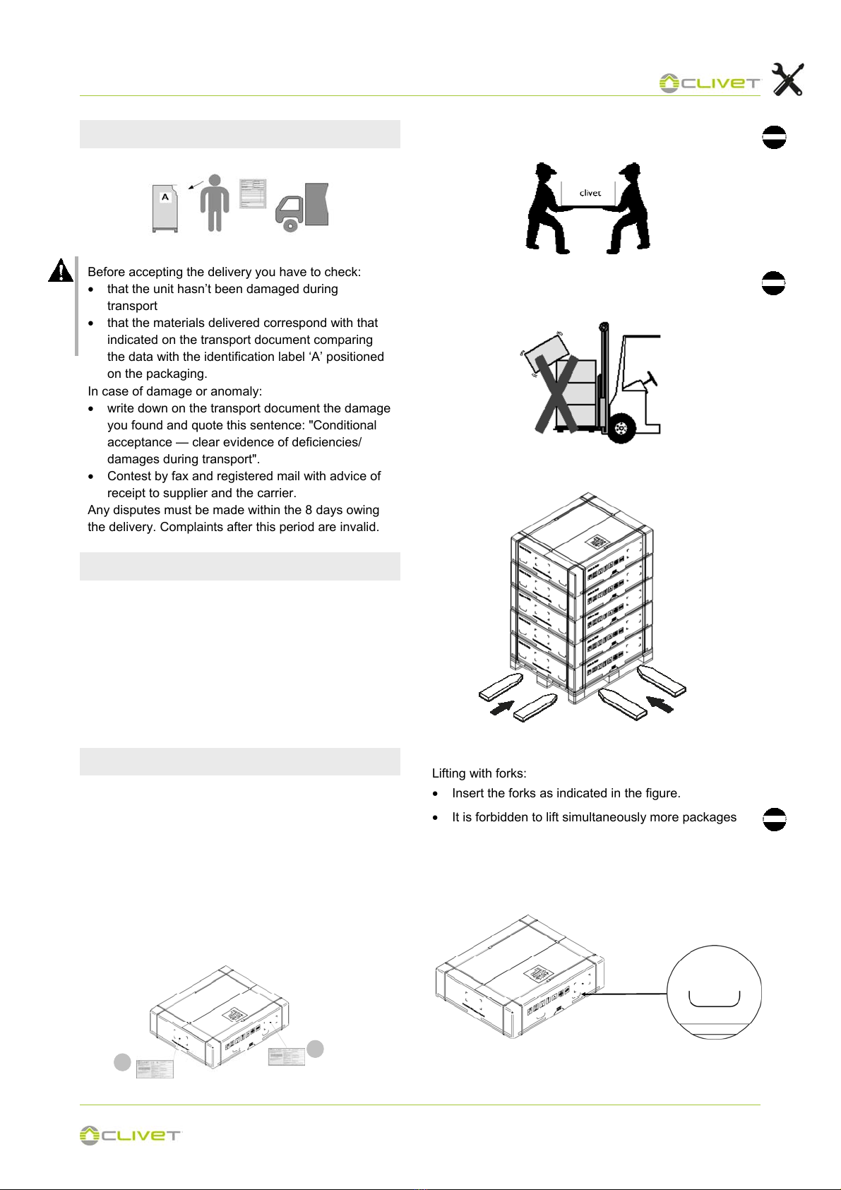
Lifting with forks:
• Insert the forks as indicated in the figure.
• It is forbidden to lift simultaneously more packages
letting them looses.
• In case of lifting of more units at the same time, an
appropriate container must be used.
Before accepting the delivery you have to check:
• that the unit hasn’t been damaged during
transport
• that the materials delivered correspond with that
indicated on the transport document comparing
the data with the identification label ‘A’ positioned
on the packaging.
In case of damage or anomaly:
• write down on the transport document the damage
you found and quote this sentence: "Conditional
acceptance — clear evidence of deficiencies/
damages during transport".
• Contest by fax and registered mail with advice of
receipt to supplier and the carrier.
Any disputes must be made within the 8 days owing
the delivery. Complaints after this period are invalid.
DELIVERY CONTROL
HANDLING
• Do not leave loose packages during the transport
• Do not trample
The following examples are indications; the choice of
the means and of the handling modes will depend on
factors, such as:
• The unit weight
• Type and overall dimensions of the unit
• Place and route for the handling (dirt yard,
asphalted square, etc.)
• Condition of the place of destination (roof, square,
etc.) distances, drops and gradients.
Shelter from: direct sunlight, rain, sand and wind.
Stocking temperature:
maximum 50°C
minimum -10°C
The respect of the instructions on the exterior side of
the packaging assures the physical and functional
integrity of the unit for the final user’s advantage.
STORAGE Max 5
A
A Lifting handle
14
2 - RECEPTION
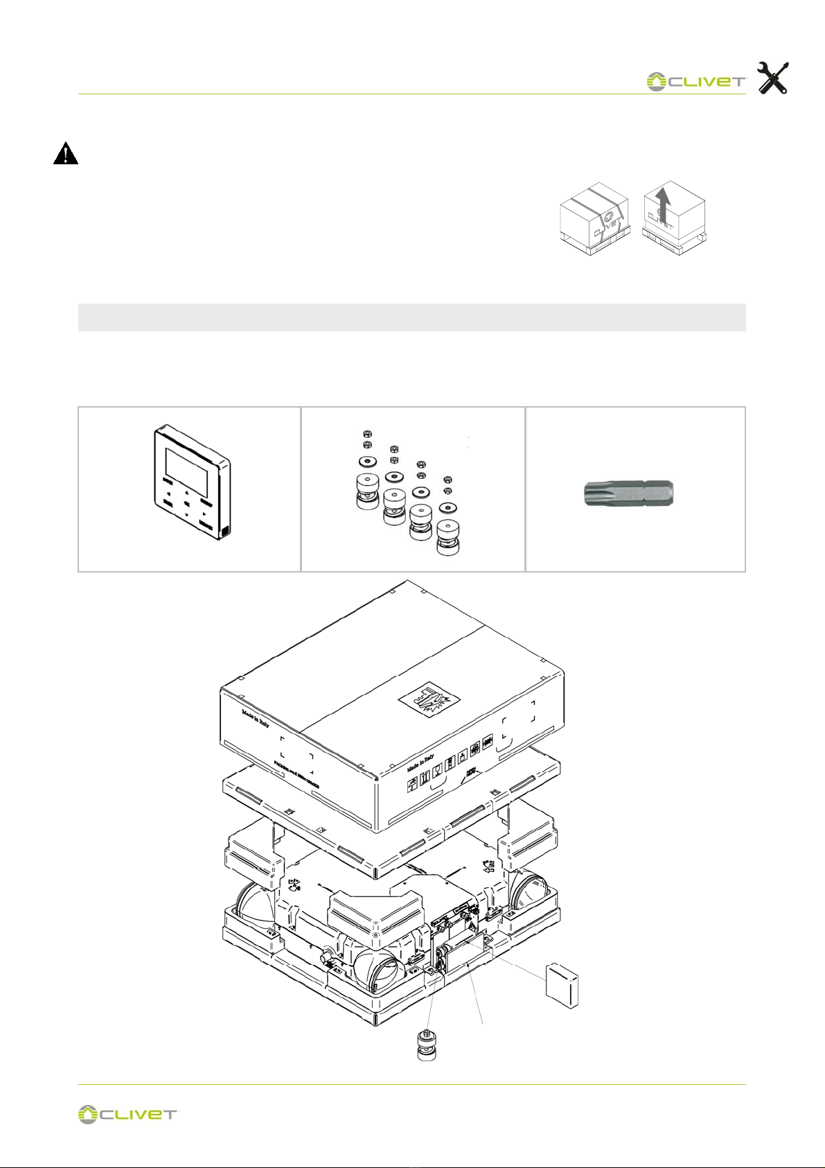
KIT REMOVAL
The unit is supplied in a single pack and is equipped with:
Packing removing
Be careful not to damage the unit.
• Cut the fixing strips.
• Remove the packaging lifting it upwards.
Keep packing material out of children's reach it may be dangerous.
Recycle and dispose of packing material in conformity with local regula-
tions.
HMI keyboard
The unit is supplied in a single pack and is equipped with:
Anti-vibration Torx insert for screwdriver
HMI keyboard
Anti-vibration Manuale
15
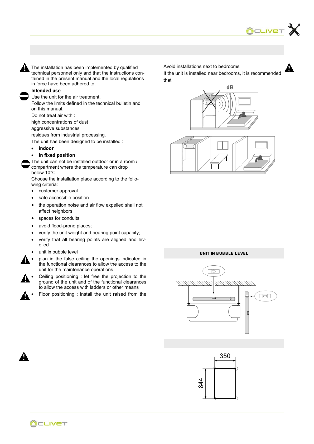
3 - POSITIONING
The installation has been implemented by qualified
technical personnel only and that the instructions con-
tained in the present manual and the local regulations
in force have been adhered to.
Intended use
Use the unit for the air treatment.
Follow the limits defined in the technical bulletin and
on this manual.
Do not treat air with :
high concentrations of dust
aggressive substances
residues from industrial processing.
The unit has been designed to be installed :
• indoor
• in fixed position
The unit can not be installed outdoor or in a room /
compartment where the temperature can drop
below 10°C.
Choose the installation place according to the follo-
wing criteria:
• customer approval
• safe accessible position
• the operation noise and air flow expelled shall not
affect neighbors
• spaces for conduits
• avoid flood-prone places;
• verify the unit weight and bearing point capacity;
• verify that all bearing points are aligned and lev-
elled
• unit in bubble level
• plan in the false ceiling the openings indicated in
the functional clearances to allow the access to the
unit for the maintenance operations
• Ceiling positioning : let free the projection to the
ground of the unit and of the functional clearances
to allow the access with ladders or other means
• Floor positioning : install the unit raised from the
ground, on a frame to permit the maintenance of
the filter (bottom extraction).
Ceiling positioning and Floor, the unit for these two
type of installation is selled with the protection fairing
in sheet metal
Limit vibration transmission:
• use antivibration devices on unit bearing/
supporting points
• install flexible joints on the hydraulic/aeraulic con-
nections.
Neglecting these aspects may decrease the unit per-
formances and life.
CLEARANCE ACCESS RECOMMENDED
UNIT IN BUBBLE LEVEL
UNIT FIXING POINTS
Consider sound emissions
Avoid installations next to bedrooms
If the unit is installed near bedrooms, it is recommended
that
The functional clearances have to :
• guarantee the unit good operating
• allow the maintenance operations
• safeguard the authorized operators and the ex-
posed person.
• position the unit taking into consideration the clear-
ances indicated in the dimensional
• consider the space necessary for filter extraction .

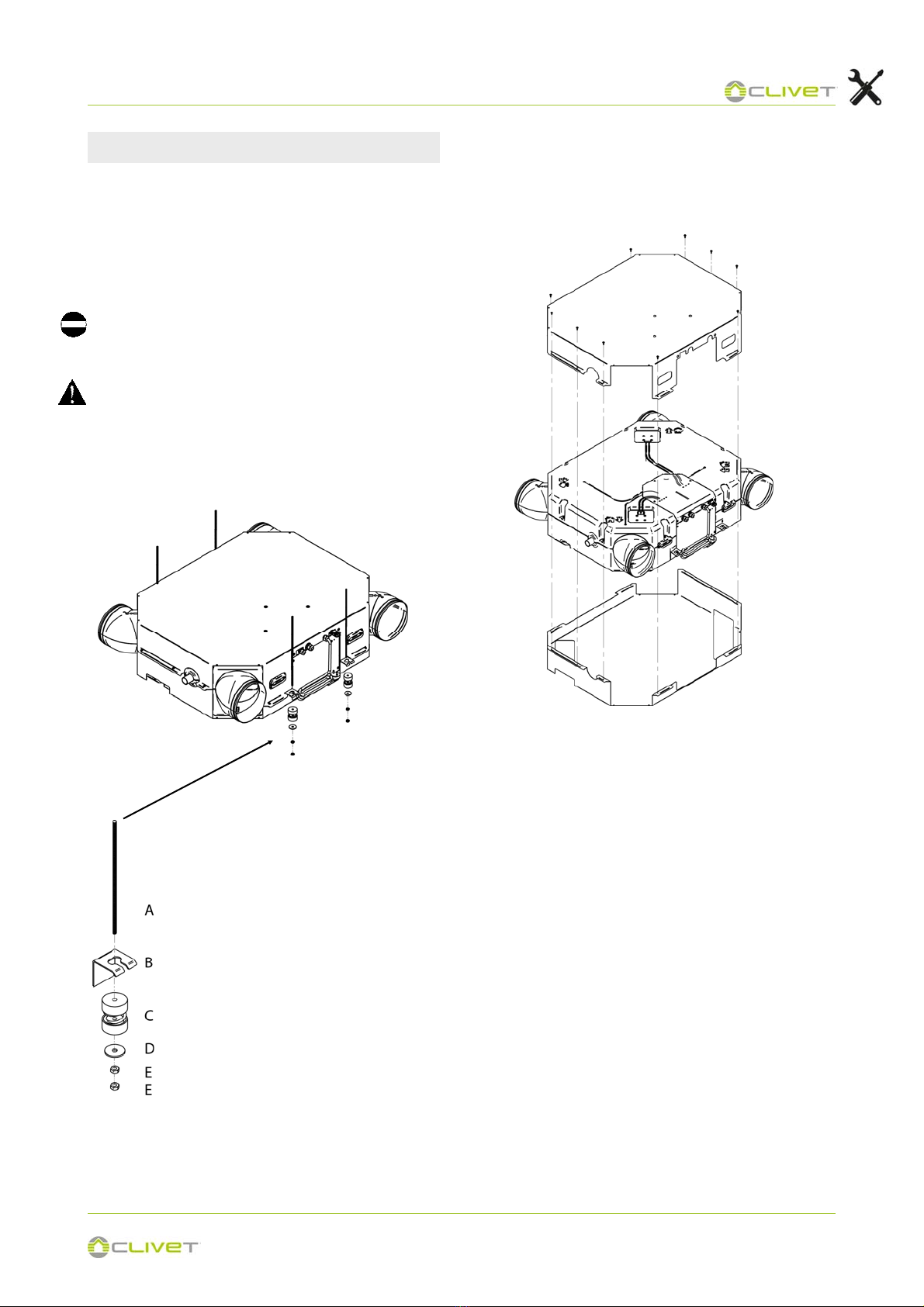
16
3 - POSITIONING
• Insert the M8 threaded bar (not supplied) to on the
support base.
• Screw the nuts, insert the flat washer.
• Insert the antibration
• Pass the M8 threaded rods into of the support
bracket on the unit.
• Insert the flat washer
• Screw the nut
• Do not over tighten the nuts, the springs, because if
too much crushed they don’t absorb vibrations
FLOOR INSTALLATION
a) nut
b) flat washer
c) bracket
d) antivibration foot
e) flat washer
f) nut
g) nut
h) A threaded bar
Perfomer by customer
For floor positioning or installation not in false ceiling the
unit provided with sheet metal cover.
17
3 - POSITIONING
CEILING INSTALLATION
• Fix some M8 threaded bars (not supplied) to the
ceiling.
• Pass the M8 threaded bars in the brackets on the
unit.
• Insert on the threaded bar the antivibration .
• Insert the flat washer and tighten the nut to lock.
• Do not over tighten the nuts, the springs, because if
too much crushed they don’t absorb vibrations
For floor positioning or installation not in false ceiling
the unit provided with sheet metal cover.
a) A threaded bar
b) Bracket
c) Antivibration foot
d) Flat washer
e) Nut
Closing housing

18
3 - POSITIONING
ELECTRIC PANEL
Access to the electrical panel
Sheet metal cover of the electrical panel fixed by
4 torx screws.
Remove the 4 torx screws.

19
3 - POSITIONING
1,5 m
OK
AMBIENT KEYBOARD
The choice of the installation point is decisive for the
environmental comfort and the energy consumption.
The thermostat must be placed :
• In a room with medium temperature and humidity
conditions, representative of the other rooms
• at a height of 150 cm
• preferably on an internal wall
Positions to avoid :
• next to heat sources
• points exposed to direct sunlight
• in a position with air rejected from outlets or
diffusers
• behind curtains or pieces of furniture
• near windows and doors to the outside
• on walls crossed by fireplaces or heating ducts
• on external walls.
Use straight head screwdriver to insert into the buc-
kling position in the bottom of keyboard, and spin the
screwdriver to take down the back cover. (Pay atten-
tion to spinning direction, otherwise will damage the
back cover!)
Use three GB950-86 M4X20 screws to directly install
the back cover on the wall.
Use two M4X25 GB823-88screws to install the back
cover on the 86 electrician box, and use one GB950-
86 M4X20 screws for fixing on the wall.
Adjust the length of two plastic screw bars in the ac-
cessory to be standard length from the electrical box
screw bar to the wall. Make sure when install the screw
bar to the wall, make it as flat as the wall.
Use cross head screws to fix the keyboard bottom co-
ver in the wall through the screw bar. Make sure the
keyboard bottom cover is on the same level after in-
stallation, and then install the keyboard back to the
bottom cover.
Over fasten the screw will lead to deforma tion of back
cover.

20
3 - POSITIONING
Buckling
position
Straight head
screwdriver
Back cover
Front cover
Screw hole installed on the wall,use
three GB950-86 M4X20
Screw hole fixed on the wall,use one
GB950-86 M4X20
A- Screw hole installed on 86 Electri-
cian box, use two M4X25 GB823-88
Back cover
Signal
switching
wires
Cutting place of left
down side wire outlet
Left down side
wire outlet
Wiring hole
Wall hole and wiring hole
Diameter 8--10
After adjusting the front cover and then buckle the front
cover; avoid clamping the communication switching wire
during installation.
Sensor can not be
affected with damp.
A
Electrician box
B
C
B
C
B -Trap
C - Putty
C
B
Avoid the water enter into the
wired remote controller, use trap
and putty to seal the connectors
of wires during wiring installation.
Table of contents
Other CLIVET Air Cleaner manuals


Popular Air Cleaner manuals by other brands

Heylo
Heylo PF1000 Translation of the original instruction manual

Hunter
Hunter HEPAtech 30027 Manuel d'utilisation

Sharp
Sharp FP-J50 Operation manual

Guardian
Guardian AC151 Use & care instructions

Ionic Pro
Ionic Pro TA750 owner's manual

Ultravation
Ultravation Solaris SLX1024 Installation and owner's manual


