CLIVET ELFOFresh2 CPAN-U 70-120 Series User manual

INSTALLATION AND OPERA-
TING MANUAL
Change living home
ELFOFresh2 70-120
ELFOFresh2200-500
make up and purification unit with active thermodynamic
recovery
ELFOFresh2CPAN-U 70-500
18-09-2019
M05E40C15-06

2
Dear Customer,
We congratulate you on choosing an ELFOSystem product, the air
conditioning system at annual cycle that offers the possibility in a sole
system of meeting all the heating, conditioning and domestic hot water
needs, purifies and renews the air
Clivet is being working for years to offer systems able to assure the
maximum comfort for long time with high reliability, efficiency , quality and
safety. The target of the company is to offer advanced systems, that assure
the best comfort, reduce the energy consumption, the installation and
maintenance costs for all the life-cycle of the system.
With this manual, we want to give you information that are useful in all the
phases: from the reception, to the installation and use until the disposal so
that a system so advanced offers the best procedure of installation and use.
Best regards and have a nice reading !
CLIVET Spa

3
1 - GENERAL
It is advisable to read it carefully so you will save time during
operations.
Follow the indications so you will not cause damages to things
and injuries to people
Before going ahead with operations, read the GENERAL
WARNINGS on page 97
Pay particular attention to :
WARNING, identifies particularly important operations or
information
PROHIBITIONS, identifies operations that must not be
carried out, that compromises the operating of the unit or
may cause damages to persons or things.

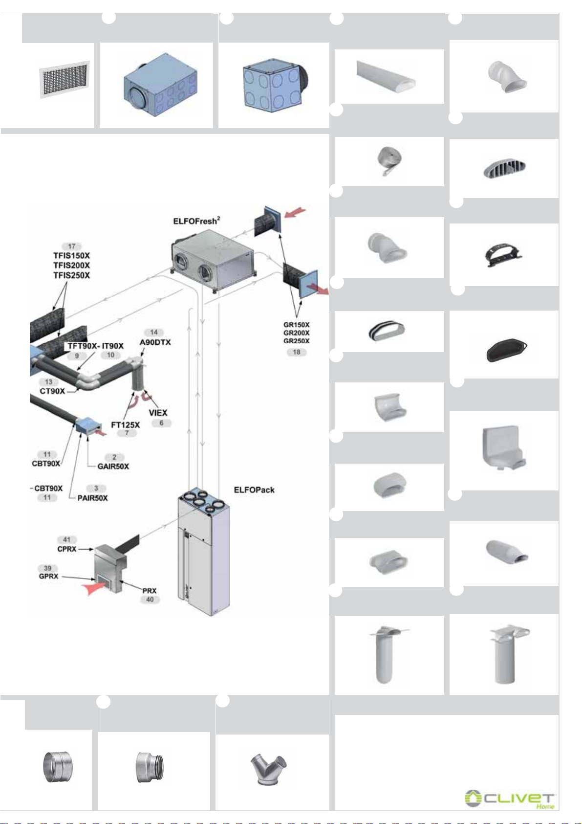
GF150X
GF200X
GF250X
GPRX
TFT90X
DN90 round flexible tube (Int. diam.
78mm) in a 20m. coil without insulation
A90DTX
90-degree adaptor, double
DN90 round tube for DN125 valve + cap
VIEX
Extraction/intake valve in ABS
DN125 without air filter
CBT90X
Connector to distribution box for
DN90 round tube
DAIR50X - DAIR80X
AIRJET 50/I - 80/l supply diffuser -
white frame and black inside
PAIR50X- PAIR80X
Suction/supply plenum with AIRJET 50
- 80 control damper - rear connection
GIUTX
Connecting joint for DN90 round tube
GINOX - GIVEX
Suction/supply rectangular grill
350x130mm stainless or white
CT90X
Printed curve of 90-degree
angle for DN90 round tube
IT90X
Insulation in a 20mt. coil for
DN90 round flexible tube
GAIR50X - GAIR80X
Intake grille + extractable filter AIRJET
50/A - 80/A - white frame and black
inside
ANFTX
DN90 seal O-Ring (10 pcs.)
FREX
Filter for rectangular
grilles 350x130mm (5 pcs.)
FT125X
Filter for DN125 valve (5 pcs.) TACTX
Cap for DN90 round tube (5 pcs.)
2
3
5
4
6
7
10
11
12
13
14
15
16
GR150X-GR200X- GR250X
Exhaust / return squared wall grig with
circular coupling DN150/200/250
TFIS150X - TFIS200X -
TFIS250X
DN150/200/250 soundproofing insulated
flexible tube in a 10mt. coil
17
18 19
PRX
Soundproofed plenum for air
recirculation
CPRX
Manifold for DN150-200 air
recirculation plenum
1 41 40 39
GQIEX
Extraction/intake squared grill of
DN125 joint with air filter
8
9
MTOA40M14-02 04-05-16
R2015X - R2520X
DN200-DN150 reducer
DN250-DN200 reducer
DY200X
DN200-DN200-DN200 Y-joint
DY250X
DN250-DN200-DN200 Y-joint
20 21
A90GPX
90-degree adaptor, single tube
for flat grill 350x130 mm
RTPTX
Round/flat tube connecting joint
A90DPX
90-degree adaptor, double flat
tube for DN125 valve
ADMPX
Straight adaptor, single flat tube
for DN125 valve
TACPX
Cap for flat tube (5 pcs.)
A90MPX
90-degree adaptor, single tube
for DN125 valve
REPPX
Flow controller for flat tube
ANFPX
Fixing ring for flat tube (10 pcs.)
29 22
23
25
26
27
24
BD14CX
14-output distribution box,
DN200 joint
BD8CX
8-output distribution box,
DN150-200 joint
ELFOAir
TFPNX
Flat flexible tube 132x52mm
in a 20m. coil without insulation
IT100X
Insulation in a 20mt. coil
for flat flexible tube 132x52
35
COBPX
DN90 connector joint
(CBT90X) --> flat tube
34
GIUPX
Seal and connecting joint
for flat tube (10 pcs.)
33
CVP90X
Vertical 90-degree curve
for flat tube
32
COP90X
Horizontal 90-degree curve
for flat tube
31
CTP180X
Joint for 180-degree
flat tube rotation
30
38 37 36 28
Grill for recirculation air
return plenum 325x175
mm white
F/F DN150/200/250
joint

!
! Filter
Filter only on the
intake grille

!
Cover the plenum, openings, grilles with cardboard,
adhesive tape, etc...
Remove caps

Consider sound emissions
CPAN-U 70-120
Aeraulic ducts
Respect the spaces to conduct normal and extraordinary maintenance
Avoid air bypass
Avoid installations next to
bedrooms
Trapdoor opening
9
A
Should not be tilted towards unit
L = 1,5 m = max. distance between resistances and electrical panel
CPAN-U 200-500
Remote electric panel
CPAN-U 200-500
Humidifier (option)
Water supply Condensate discharge
C
** Insulated ducts
Install in a local or compartment where the temperature can't drop below 0 ° C.
F
For details see the manual
sections
Size 70-120 200-300 500
A (mm) 636 666 710
B (mm) 755 760 993
B
* extraction air filters from below
Anti-vibration joint when used rigid pipes
Size 70-120
A Air expulsion Ø 150 mm
B Ambient air
return Ø 150 mm
C Ambient air
distribution Ø 150 mm
D Fresh air
intake Ø 150 mm
200-300
Ø 200 mm
Ø 200 mm
Ø 200 mm
Ø 200 mm
500
Ø 250 mm
Ø 250 mm
Ø 250 mm
Ø 250 mm
Filter size 200-500
Electric heaters (option)
E
HID-P1 ambient thermostat
H
Connect the ambient thermostat to the terminal block of the
customer connections
Terminal block of
the customer
Connections
Cable 3x0,34 mm2 shielded
Max. length 80 m
Unit fixing points
Install supplied antivibration
Dimensions connections
Install an air filter upstream. This should be at
least a G2 class filter to protect the heating
elements (provided by the customer)
ATTENTION
Don't invert downwards

MT5E40M15-06 19-09-19
Condensate discharge
CPAN-U 70-120
Rapid guide
ELFOFresh2
CPAN-U 200-500 Space to access:
* 700 - filter access from below, electrical panel on
board unit
* 200 - filter access from below, remote electrical
panel
Sloping tube
D
Avoid tight bends
Safety grilles CPAN-U 200-500
CPAN-U 70-120
Front
Rear
I
BEFORE REQUESTING START-UP
Completed system
Completed aeraulic system and free of dirt
Electric connections
AE fresh air intake
ES air expulsion
Mambient air distribution
Rambient air return
Pipe length
If there are electric heaters,
increase access space
Trapdoor opening
Sifón
Document reference
M05E40C15
** extraction air filter from below
Insulate the
steam-pipe
Slope min. 20°
Electric connections
G
Insulated ducts
Size A B
70-120 226 206
200-300 310 276
500 370 336
Positions thermostat
1,5 m
OK
The thermostat must be placed:
x at a height of 150 cm
x preferably on an internal wall
x Positions to avoid:
x next to heat sources
x points exposed to direct
sunlight
x Ecc….
Pag. 22/26/30
Ceiling access
Standard pump

10
CPAN-U 70 - 120
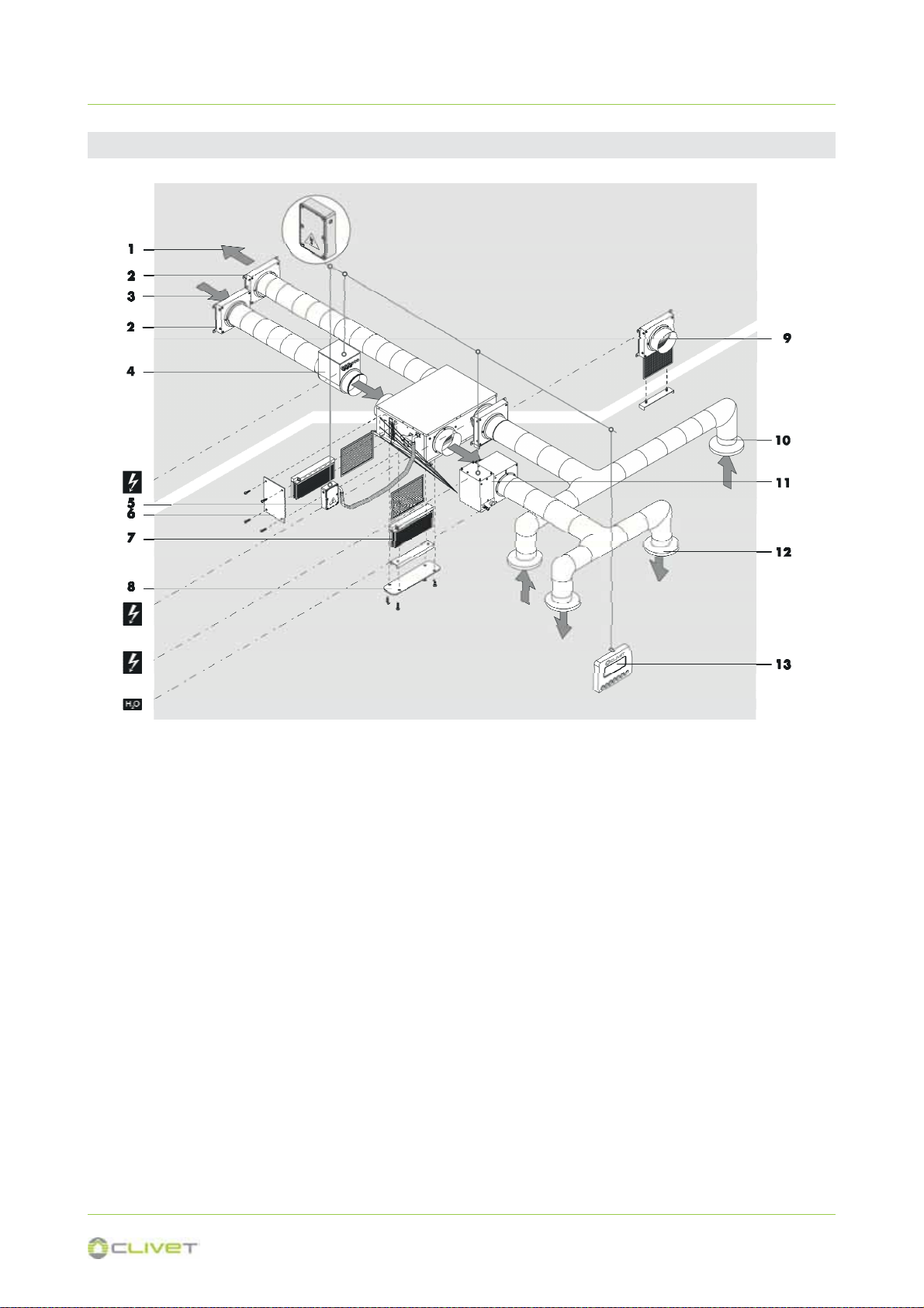
1 - GENERAL
1.1 UNIT DESCRIPTION
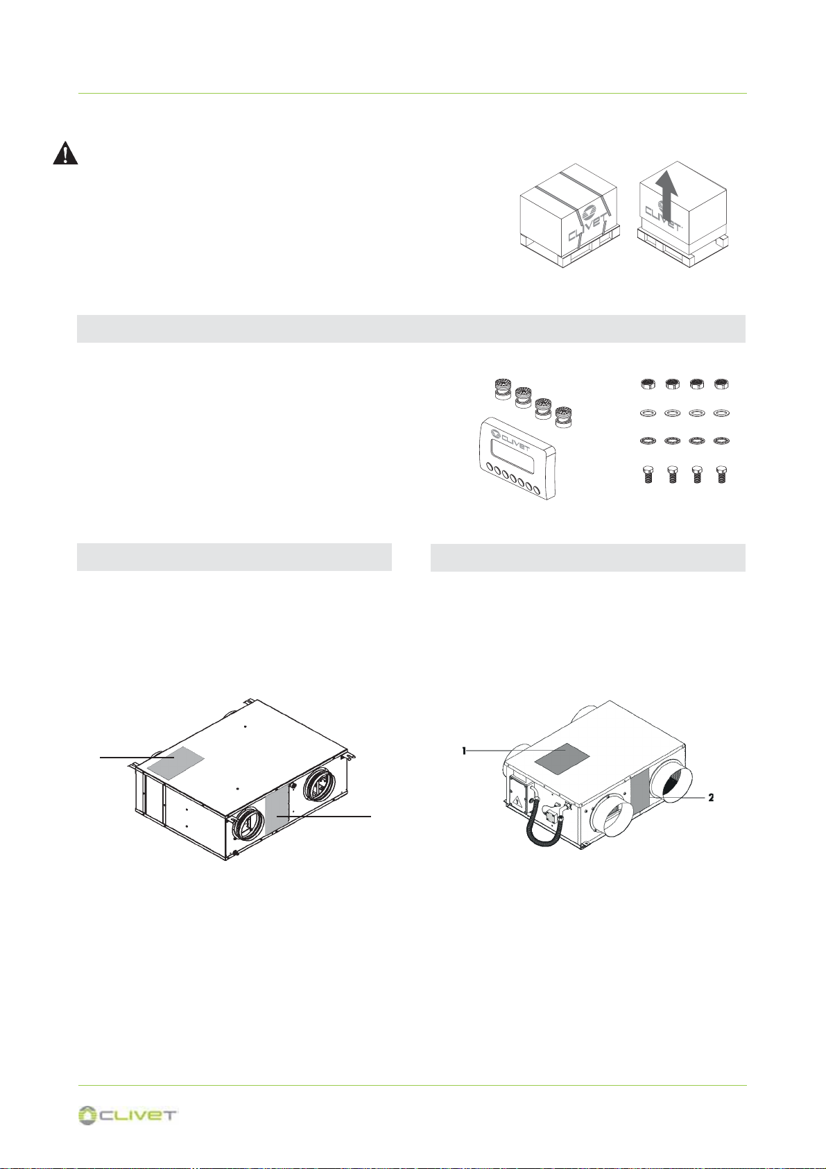
1 Serial number label
2 Exhaust air fan
It rejects the unhealthy air outdoors.
3 Internal exchanger
It transfers energy (heat / cool) to the fresh air .
4 Compressor
5 Supply fan
It blows treated air in the rooms.
CPAN-U 200 - 500
7 Electrical remote panel
It is possible to remove the electrical panel and
make it remote to facilitate the installation
8 External exchanger
It recovers energy (heat / cool) from the exhaust air.
9 Air filter
It purifies the fresh air before introducing it into the
rooms
10 Upper panel
11 Electronic filter (option)
12 Electrical panel

11
CPAN-U 70 - 120
1 - GENERAL
1.2 ACCESSORIES
1 Ambient exhaust air
2 Grid to prevent small animals or leaves from
entering inside (option)
3 Outdoor air intake
4 Kit of electric resistance (option)
5 Intake air filter
6 Customer connections
7 Electronic filter (option)
8 Exhaust air filter
9 Ambient air intake
10 Ambient air supply
11 HID-P1 ambient thermostat
CDPX : Discharge condensate pump (size 200-500)
EHPCX : Preheating elements 0,7 kW in duct (size 70-120)
Preheating elements 1,5/3 kW in duct (size 200-500)
FSEX : Electronic filter kit (size 70-500)
HSE3LX: Immersed electrode steam humidifier for Elfofresh DN200 (size 200-500)
HSE3MX: Immersed electrode steam humidifier for Elfofresh DN250 (size 200-500)
FAEX : Kit of exhaust air filter (size 200-500)
CMMBX : Serial communication moduleto supervisor (MODBUS)
ELFOAir
Is the air distribution system.
12
1 Ambient exhaust air
2 Grid to prevent small animals or leaves from entering inside (option)
3 Outdoor air intake
4 Kit of electric resistance (option)
5 Remote electrical panel
6 Filter extraction with remote electrical panel
7 Electronic filter (option)
8 Filter extraction with built-in remote electrical panel
9 Kit of exhaust air filter (optional)
10 Ambient air intake
11 Humidifier kit (optional)
12 Ambient air supply
13 HID-P1 ambient thermostat
CPAN-U 200 - 500
1 - GENERAL
13
1.3 UNIT IDENTIFICATION
Serial number label
The serial number label is positioned on the unit,
generally next to the electrical panel, and allows you to
indentify all the unit features.
The serial number label has not to be removed for any
reason.
It reports the regulations indications such as:
x Type of unit
x size ĺ
x serial number
xxxxxxxxxxxx
x year of manufacture
x wiring diagram number
x electrical data
x manufacturer logo and address
Serial number
It identifies uniquely each unit.
It identifies specific spare parts for the unit.
Intervention requests
Note data from the serial number label and write them
in the table sideways, so you will find them easily when
needed.
In case of intervention you have to provide the data
indicated sideways.
Serie
Size
Serial number
Year of manufacture
Wiring diagram
1 - GENERAL
When ordering repair parts please always give the fol-
lowing information:
Model, serial and product number.
Parts name.
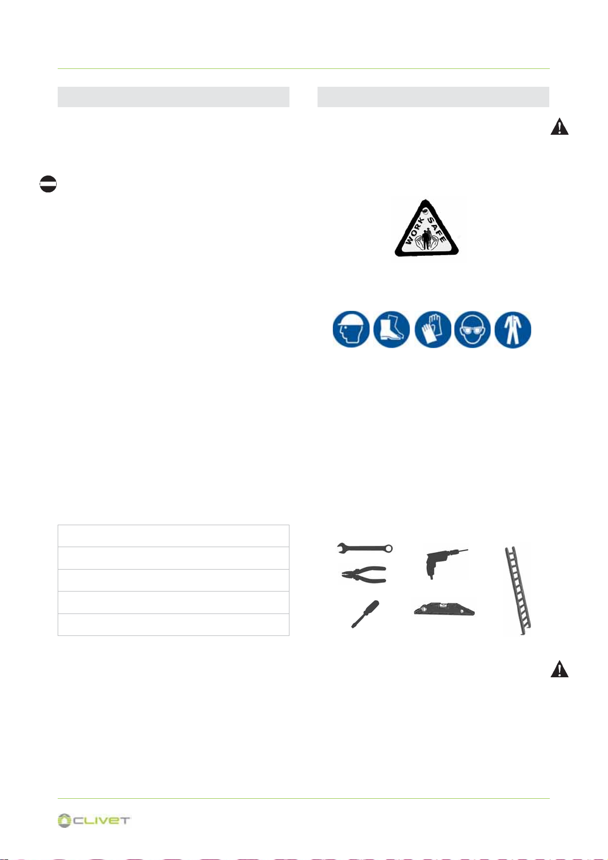
Operate in compliance with safety regulations in force .
Use single protection devices.
BEFORE REQUESTING START-UP
x Completed system
x Completed aeraulic system and free of dirt
x Electric connections
Before beginning the work, ensure you that have the
final project for installing the aeraulic, hydraulic, elec-
tric,drains and positioning the units.
Recommended instruments
Set of Philips and flathead screwdrivers;
Cutters;
Drill;
Scissors;
Set of open spanners or pipe wrenches;
Range;
Hydraulic material for the sealing of the threads;
Electrical equipment for the connections;
Cut prevention gloves;
Tester and amperometric pliers.
PRELIMINARY INFORMATION
14
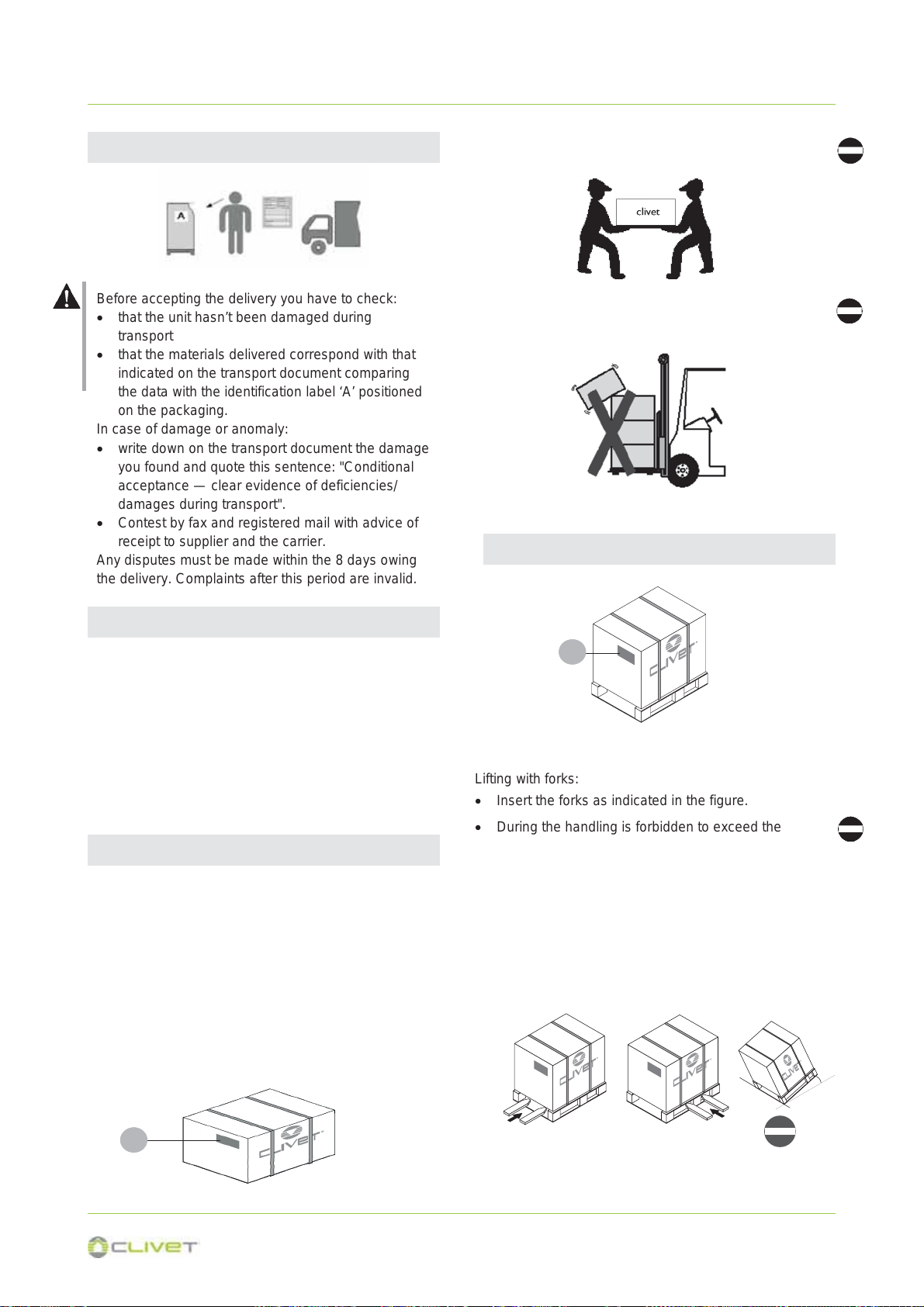
2 - RECEPTION
Lifting with forks:
x Insert the forks as indicated in the figure.
x During the handling is forbidden to exceed the
maximum allowable inclination as indicated in the
figure.
x It is forbidden to lift simultaneously more packages
letting them looses.
x In case of lifting of more units at the same time, an
appropriate container must be used.
A
30°
Before accepting the delivery you have to check:
x that the unit hasn’t been damaged during
transport
x that the materials delivered correspond with that
indicated on the transport document comparing
the data with the identification label ‘A’ positioned
on the packaging.
In case of damage or anomaly:
x write down on the transport document the damage
you found and quote this sentence: "Conditional
acceptance — clear evidence of deficiencies/
damages during transport".
x Contest by fax and registered mail with advice of
receipt to supplier and the carrier.
Any disputes must be made within the 8 days owing
the delivery. Complaints after this period are invalid.
2.1 DELIVERY CONTROL
CPAN-U 70 - 120
CPAN-U 200 - 500
A
A
x Do not leave loose packages during the transport
x Do not trample
The following examples are indications; the choice of
the means and of the handling modes will depend on
factors, such as:
x The unit weight
x Type and overall dimensions of the unit
x Place and route for the handling (dirt yard,
asphalted square, etc.)
x Condition of the place of destination (roof, square,
etc.) distances, drops and gradients.
Shelter from: direct sunlight, rain, sand and wind.
Stocking temperature:
maximum 50°C
minimum -10°C
The respect of the instructions on the exterior side of the
packaging assures the physical and functional integrity of the
unit for the final user’s advantage.
2.2 - STORAGE
15
2 - RECEPTION
A
G
B
C
D
E
F
2.2 KIT REMOVAL
CPAN-U 70 - 120 CPAN-U 200 - 500
The unit is supplied in a single pack and is equipped
with:
1 installation manual
2 installation kit - Ambient thermostat
Installation kit
A spring antivibrations n.4
B M8 nuts n.4
C plain washers n.4
D toothed washers n.4
E M8 bolts n.4
F ambient thermostat
The unit is supplied in a single pack and is equipped
with:
1 installation manual
2 installation kit - Ambient thermostat
1
2
Packing removing
Be careful not to damage the unit.
x Cut the fixing strips.
x Remove the packaging lifting it upwards.
x Remove the protective nylon.
Keep packing material out of children's reach it may be dangerous.
Recycle and dispose of packing material in conformity with local regula-
tions.

16
3 - POSITIONING
The installation has been implemented by qualified
technical personnel only and that the instructions con-
tained in the present manual and the local regulations
in force have been adhered to.
Intended use
Use the unit for the air treatment.
Follow the limits defined in the technical bulletin and
on this manual.
Do not treat air with :
high concentrations of dust
aggressive substances
residues from industrial processing.
The unit has been designed to be installed :
x indoor
x in fixed position
The unit can not be installed outdoor or in a room /
compartment where the temperature can drop
below 0 ° C.
Choose the installation place according to the follo-
wing criteria:
x customer approval
x safe accessible position
x the operation noise and air flow expelled shall not
affect neighbors
x spaces for conduits
x avoid flood-prone places;
x verify the unit weight and bearing point capacity;
x verify that all bearing points are aligned and lev-
elled
x unit in bubble level
x plan in the false ceiling (or in the floor) the open-
ings indicated in the functional clearances to allow
the access to the unit for the maintenance opera-
tions
x Ceiling positioning : let free the projection to the
ground of the unit and of the functional clearances
to allow the access with ladders or other means
x Floor positioning : install the unit raised from the
ground .
Limit vibration transmission:
x use antivibration devices on unit bearing/
supporting points
x install flexible joints on the hydraulic/aeraulic con-
nections.
Neglecting these aspects may decrease the unit per-
formances and life.
3.1 CLEARANCE ACCESS RECOMMENDED
UNIT IN BUBBLE LEVEL
Size 70-120 200-300 500
A (mm) 636 666 710
B (mm) 755 760 993
UNIT FIXING POINTS
Consider sound emissions
Avoid installations next to bedrooms
If the unit is installed near bedrooms, it is recommended
that acoustic insulation is arranged.
The functional clearances have to :
x guarantee the unit good operating
x allow the maintenance operations
x safeguard the authorized operators and the ex-
posed person.
x position the unit taking into consideration the clear-
ances indicated in the figure.(following pages)
x consider the space necessary for return ambient
filter extraction (see option).
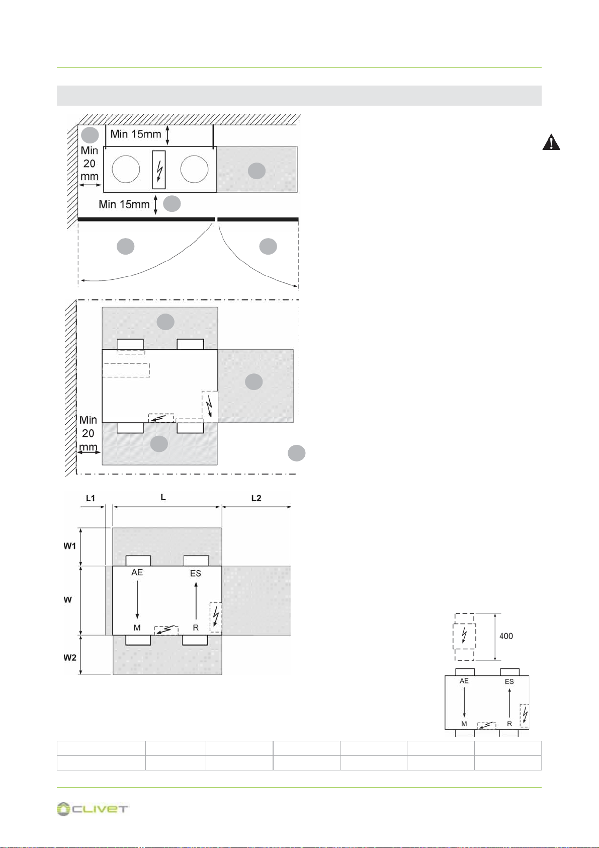
17
3 - POSITIONING
Mod L1 L L2 W1 W W2
70 - 120 20 mm 800 mm 500 mm 300 mm 590 mm 300 mm
AE fresh air intake
ES air expulsion
MAmbient air distribution
RAmbient air return
CPAN-U 70 - 120
A Distance to prevent vibrations from being
transmitted.
B Trap door for routine maintenance (access to the
connections of the electrical panel, air filters and
the optional electronic filter)
C Trap door for extraordinary maintenance
D Access to the electrical panel
E Access to clean the filter (air filters)
F Access to conduct extraordinary maintenance (to
replace the fan, compressor, etc.)
Heat. el. = If there are heating elements, increase the W1
value (information on heating elements on page 71)
Heat. el.
D
A
A
CB
D
E
E F

18
3 - POSITIONING
Mod L1A L1B L1C L L2 W1 W W2
200 700 mm 400 mm 200 mm 920 mm 20 mm 300 mm 704 mm 300 mm
300 700 mm 400 mm 200 mm 920 mm 20 mm 300 mm 704 mm 300 mm
500 700 mm 400 mm 200 mm 1158 mm 20 mm 300 mm 741 mm 300 mm
CPAN-U 200 - 500
AE fresh air intake
ES air expulsion
MAmbient air distribution
RAmbient air return
CPAN-U 200 - 500
A Space to access the electrical panel
B Space necessary for the by-pass damper
C Distance to prevent vibrations from being transmitted
(insert a neoprene sheet)
D Trap door for routine maintenance (access to electrical
panel and optional electronic filter)
E Access to conduct extraordinary maintenance (to
replace the fan, compressor, etc.)
F Access to fan removal
G Access to clean the filter (exhaust air filter - option)
Heat. el. = If there are heating elements, increase the W1
value (information on heating elements on page 79)
Heat. el.
L1A ceiling installation, filter access from below, non-remote electrical control board at a distance
floor installation, lateral filter access, non-remote electrical control board at a distance
L1B floor installation, lateral filter access, remote electrical control board at a distance
L1C ceiling installation, filter access from below, remote electrical control board at a distance
A
B
C
E
D
A
F
G
F
G
19
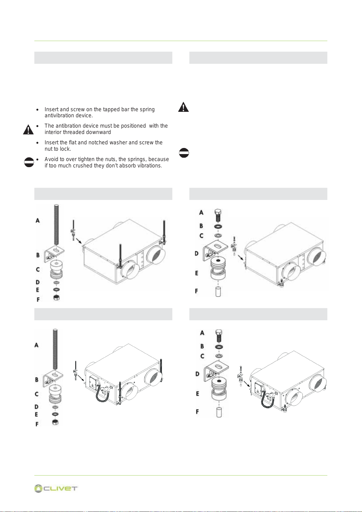
x Fix some M8 threaded bars (not supplied) to the
ceiling.
x Pass the M8 threaded bars in the brackets on the
unit.
x Insert and screw on the tapped bar the spring
antivibration device.
x The antibration device must be positioned with the
interior threaded downward
x Insert the flat and notched washer and screw the
nut to lock.
x Avoid to over tighten the nuts, the springs, because
if too much crushed they don’t absorb vibrations.
x Insert the M8 threaded bar on the support base.
x Match the upper hole of the antivibration device
with the hole of the support bracket.
x The antibration device must be positioned with the
interior threaded upward.
x Insert the flat and notched washer in the bolt.
x Screw the bolt in the top of the antivibration device
letting it pass through the hole on the bracket.
x Do not over tighten the nuts, the springs, because if
too much crushed they don’t absorb vibrations
3 - POSITIONING
3.2 CEILING POSITIONING 3.3 FLOOR POSITIONING
A threaded bar
B bracket
C antivibration foot
D flat washer
E notched washer
F nut
A bolt
B notched washer
C flat washer
D bracket
E antivibration foot
F threaded bar
CPAN-U 70 - 120 CPAN-U 70 - 120
CPAN-U 200 - 500 CPAN-U 200 - 500

20
The electrical panel is provided assembled on the unit
side but if necessary it can be remotely controlled up to
2 mt. away.
Electric panel
3 - POSITIONING
3.4 ELECTRIC PANEL
CPAN-U 70 - 120 CPAN-U 200 - 500
Remote positioning
x Unscrew the fixing screws and remove the
electrical panel cover.
x Unscrew the fixing screws (M6) and remove the
panel from the unit side.
x Fix the panel using screws and screw anchors
suitable for the characteristics of the used support.
x If later it is supposed the installation of the electric
elements (optional) consider that the cable to
connect to the electrical panel has a max length of
1,5 metres.
x In this case the filter removal for cleaning can be
performed either from the side or from below.
Access to the electrical panel:
Afrom below
Blateral
A
B
L = 2mt
Other manuals for ELFOFresh2 CPAN-U 70-120 Series
1
This manual suits for next models
2
Other CLIVET Air Cleaner manuals


