CLIVET AQX CLA Series User manual

Installation use and maintenance manual
AQX - CLA 1 - 32
Modular air-handling units
MU14B006GB-01 19-01-2015

Dear Customer,
Congratulations for having chosen this product.
Clivet has been working for years to offer the market systems able to assure maxi-
mum and long-lasting wellbeing with high reliability, efficiency, quality and safety.
The company aim is that to offer its customers developed systems that assure the best
comfort, reduce energy consumptions and installation and maintenance costs for the
entire life-span of the system.
With this manual, we intend giving information useful throughout all phases: from
reception, to installation, to use and even disposal, so that such a developed system
meets the best installation and use methods.
With kind regards and... good reading!
CLIVET Spa

3
1 Generality ......................................... 4
2 Receipt .............................................. 6
3 Positioning ....................................... 7
4 Hydraulic connections .................... 10
5 Aeraulic connections ...................... 15
6 Electric connections ....................... 16
7 Start-up ............................................ 20
8 Maintenance ................................... 23
9 Troubleshooting ............................ 27
10 Technical information ................... 29
11 Disposal ............................................ 30
12 Residue risks .................................. 31
TABLE OF CONTENTS
The data contained in this manual are not binding and can be
changed by the manufacturer without prior notice.

4
1.1 General warnings
Purpose of the manual
This manual has been realised to enable a correct installation,
adjustment and maintenance of the unit.
Manual instructions
It is of fundamental importance that the manual is carefully
read.
Pay particular attention to:
PROHIBITIONS
indicate operations that cannot be carried out as they
jeopardise the machine operation or can cause personal
injuries or damage things.
WARNINGS
indicate potentially dangerous or damaging situations.
INFORMATION
indicate particularly useful information.
The manufacturing company declines every liability for any
damages, directly or indirectly, to persons or things, following
the non-compliance with these instructions.
Preserving the manual
This manual and the wiring diagram of the unit must be
carefully kept and be available to the operator for future
consultation.
Systems designing
Installation, electric, hydraulic system, etc., must be defined
by enabled designers in accordance with the current
standards.
Qualified personnel
The unit must be installed, tested and assisted by qualified
personnel having the legal requisites.
Installation
The installation must be carried out in accordance with the
local safety standards.
Electric network
Check that the features of the electrical network are conform
with the data on the unit matriculation plate, found on the
inside of the main electric control board.
Packaging
The packaging material (plastic bags, expanded polystyrene,
nails, etc.) must be kept out of the reach of children as it is a
potential source of danger and must be correctly recycled in
accordance with the local standards in force.
Maintenance
Disconnect the electric power supply to the unit before
carrying out any maintenance. The operations must be carried
out in accordance with the local safety
standards.
Periodical checks
Carry out periodical checks to identify any loose, damaged or
broken parts. The lack in repair
entails the risk of damages to things and personal injuries.
Fault –Malfunctioning
Disconnect the equipment in case of fault or
malfunctioning.
Repair
For any repairs, only contact an after-sales technical
assistance centre authorised by the manufacturer and request
the use of original spare parts. The non-compliance with the
above can jeopardise the safety of the equipment.
Modifications
Every liability is declined by the manufacturer with voiding of
the warranty in the event of electrical and/or mechanical
modifications. Tampering in general, not expressly authorised
and not respecting that reported in this manual, void the
warranty.
Destination of use
The unit is designed for the treatment of air with the functions
shown on the technical sheet enclosed with the machine (in
general, air handling, mixing, filtration, heating, cooling,
humidification, dehumidification, sound-proofing).
Keep to the limits foreseen in the technical schedule and in
this manual.
Any use different to that specified does not entail any kind of
commitment or obligation by the manufacturer.
Safety integration principles
The unit is designed and manufactured so as not to expose
the personal health and safety to risk.
In this regard, project solutions have been adopted act at
eliminating, where possible, the possible causes of risk or
significantly reduce the probability of the event-risk. Should it
not have been possible to intervene during designing to
prevent and/or eliminate the risk, refer to the behavioural
prescriptions reported in the residue risks section.
Data update
The continuous improvements made to the product can
determine variations to data, even without prior notice by the
manufacturer.
User training
The installer must train the user, particularly on:
Switch-on/off
Setpoint modification
Stand-by
Maintenance
What to do/not to do in case of fault.
1 -GENERALITY
!
i

5
i
Serial number label
The serial number label is found on the unit and indicates all
machine features.
The serial number label must never be removed.
The serial number label shows the indications foreseen by the
standards, in particular:
the type of machine
range → AQX
size → 1......32
the serial number
12 characters → Axxxxxxxxxxx
the year of manufacture
the wiring diagram number
electrical data
manufacturer logo and address
Serial number
Unambiguously identifies each machine.
Enables identifying the specific spare parts for the machine.
Intervention requests
From the serial number label, take note of the characteristic
data on the table so they are easily available if required.
For request of intervention, always give the following data.
Range
Size
Serial number
Year of manufacture
Wiring diagram
1 -GENERALITY
1.2 Unit identification

6
2 - RECEIPT
Use protections to avoid damaging the unit.
!
Work respecting the current safety standards.
For detailed information (dimensions, weights, technical features,
etc.) refer to the TECHNICAL INFORMATION chapter.
To perform the operations use the protective equipment:
gloves, goggles, etc.
Before accepting delivery, check:
The unit has not been damaged during tran sport. That the
delivered material corresponds to that indicated on the transport
document, comparing data with the matriculation plate positioned
on the pack.
In case of damages or anomalies:
immediately make a note of the found damage on the
transport document and write the wording: "Collection
with reserve for evident shortages/damages due to
transport".
notices via fax and with registered letter with
acknowledgement receipt to carrier and supplier.
The notifications must be made within 8 days from receipt, after
this date they will not be accepted.
2.1 Preliminary information
2.2 Check upon arrival
i
!
Check the weight of the unit and capacity of the lifting mean.
Identify the critical points in the handling path (holy paths,
ramps, steps, doors).
Check the position of the centre of gravity .
Ensure the unit is stably balanced before starting handling.
2.4 Handling
Attention not to damage the unit.
Recycle and dispose of the packaging material according to
local standards.
2.5 Removal of packaging
!
Respect the indications on the outside of the pack.
2.3 Storage

7
!
i
The functional spaces have the aim of:
guarantee good operation of the unit
allow maintenance operations
protect the authorised operators and exposed
persons.
Respect the functional spaces
A corridor whose width is equal to the length of the finned
coils (approximately equal to the width of the machine) must
be available to allow the removal of the coils.
On the sides with inspection doors, a corridor must be left to
allow the doors to be opened completely, and in any case no
less than 600mm
Double the functional spaces if more units are aligned.
3 - POSITIONING
The units have been designed to be installed :
OUTDOORS
in permanent position.
Choose the place of installation depending on the following
criteria:
level of sound emissions admitted by the local
standards
Customer approval
safely accessible position
technical spaces requested by the unit
maximum distance admitted from the electric
connections
support points with adequate capacity for the unit
weight
spaces for air ejection and suction
disposal of condense water
Prefer places where the unit does not disturb neighbours.
Avoid snow accumulating obstructing the coils
Avoid places that may be subject to floodings
Install the unit lifted from the ground.
Protect the unit with suitable fence in order to avoid
access to unauthorised personnel (children, vandals, etc.)
Limit the transmission of vibrations:
use anti-vibration devices or neoprene strips on the
unit support points
install flexible joints on the hydraulic connections
install flexible joints on the aeraulic connections.
A correct air circulation on the coil is essential to guarantee
the good operation of the machine.
Avoid:
obstacles to air flow (strong prevailing winds, hedges,
fences, etc.)
difficulty of exchange
leaves or other bodies that can obstruct the exchange
coils
winds contrasting or favouring the air flow
heat sources near the unit (chimneys, extractors, etc.)
sources of dust or pollutants
stratification (cold air that stagnates at the bottom)
recirculation (ejected air that is taken back via suction)
!
Work respecting the current safety standards.
To perform the operations use the protective equipment:
gloves, goggles, etc.
3.1 Preliminary information
3.2 Functional spaces
3.3 Positioning
Positioning on steel structure
Positioning on concrete floor
1 2 cm thick neoprene strips
2 concrete floor
3 floor
1 anti-vibration devices
2 steel structure
3 steel structure

8
3 - POSITIONING
The units installed outdoors require greater care, both for the
reasons already mentioned and due to the correct application
of the rain cover, which is subject to strong winds.
Special attention should be paid to the seal gaskets.
Any flashing fitted to the base must be installed so as to
prevent the infiltration of water, therefore pay special
attention to the gasket and the silicon seals. The height of
the step supporting the unit must be sufficient to avoid any
water or snow from stagnating and that may cause
infiltration.
If the cover is already fitted to the unit and fastened to the
roof of the casing, check for any breakages or loosening
of the screws.
If the cover needs to be installed, make sure all the
material supplied is present: sheets, stiffeners, screws.
Special attention should be paid when fitting the gasket;
use silicon to ensure a perfect seal, where required.
1. Joint protection (ABS)
2. Roof
4. Aluminium frame
5. Base
6. Waterproofing
7. Support base
4
5
6
7
2
2 1
During the installation of units consisting of a series of
sections, pay special attention to the rating plates located on
the sections.
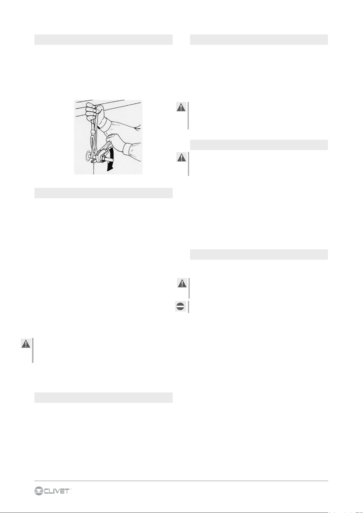
After having applied the self-adhesive gasket between the
strips on the sections being joined, bring the parts together so
that they fit perfectly. It is important during this operation to
make sure that the unit is level.
Tighten the corner gussets (Fig. a) and lock the joint using the
L-shaped nylon blocks (Fig. b).
The gasket, the blocks and the fastening screws are inside
the bag supplied.
3.4 JOINING THE SECTIONS
a
b
ROOF:
In the event of outdoor installation, a roof made from
aluminium plate is available.
The joining elements on the units divided into a series of
sections must be assembled by the customer, using the ABS
joint protections (1).

9
3 - POSITIONING
For reasons of bulk, the heat recovery units may be supplied
as separate sections or partially dismantled. In these cases,
special attention should be paid when assembling the
recovery unit, being made from fragile and delicate material.
Check that the gaskets and the silicon seals prevent the by-
pass of air.
Check that the air by-pass damper, if present, is working
perfectly, so as to ensure complete closing.
3.5 HEAT RECOVERY UNITS
STATIC CROSS FLOW RECOVERY UNIT
Check that the finned coil is not dented, broken or crushed.
ROTARY RECOVERY UNIT
Check the positioning of the recovery unit, that it is level and
that the movement of the wheel is regular and not misaligned.
Check that the fins are not damaged.
10
4 - HYDRAULIC CONNECTIONS
4.1 PRELIMINARY INFORMATION
4.3 OPERATION SEQUENCE
Before connecting the unit, carefully wash the system by filling
it and emptying it several times with clean water.
Ignoring this operation will lead to several filter cleaning inter-
ventions and at worst cases can cause damages to the e-
xchangers and the other parts.
Execute leakage test before isolate the pipes.
To avoid heat dispersions and formation of condensate isolate
all the pipes. Leave various point of service free (wells, vent-
holes etc ).
4.5 RISK OF FREEZE
4.6 ANTI-FREEZE SOLUTION
Consider that the use of anti-freeze solution determines an
increase in a pressure drop.
Make sure that the glycol type utilized is inhibited (not corrosi-
ve) and compatible with the hydraulic circuit components
(pump etc).
Do not use different glicol mixture (i.e. ethylic with propylene)
Selection and installation of system components must be
carry out by installer.
Following you will find some indications to integrate with what
is provided by the local regulations in force and by the good
technical laws.
4.2 COMPONENTS
CUT-OFF VALVES :
installed at inlet and outlet (both on the water technique
circuit as well as that of the hot domestic water) allow
maintenance operations without having to empty the
system .
THERMOMETERS AND MANOMETERS :
installed at entry and exit of the main elements facilitate
inspection and maintenance.
AN AIR BLEED VALVE :
installed in all of the highest points of the system allowing
the venting of the circuits air..
DRAINAGE TAPS :
installed in the lowest points of the system to allow
bleeding.
EXPANSION TANK :
It keeps a correct system pressure when the water
temperature changes. It must be dimensioned as a
function of water content. Could be necessary install in
addition on the unit one or more of it .
WATER FILTER :
must be installed immediately in the water input of the unit,
in a position that is easily accessible for cleaning.
The filter never should be removed, this operation
invalidates the guaranty
SUPPORTS :
The hydraulic pipes weight mustn’t burden on the unit
connections
If the unit or the relative water connections can be subject to
temperatures close to 0°C adopt measures for prevent risk of
freeze.
For example:
Mix water with ethylene glycol
Safeguard the pipes with heating cables placed under the
insulation
Empty the system in cases of long non-use and check that:
there are no closed taps present that could trap water
even after emptying
there are no low points in which water can stagnate
even after emptying; carry out any blowing required .
4.4 WATER QUALITY
The water quality is determined by the following factors, avoid
therefore:
Inorganic salts
pH
Biological load (seaweeds etc)
Suspended solids
Dissolved oxygen
Water with inadequate characteristics can cause:
pressure drop increase
energy efficiency decrease
corrosive symptom increase

11
4 - HYDRAULIC CONNECTIONS
The water coils must be installed with perfectly horizontal
pipes. They must be connected following the indications on
the plates. In any case, the fluid must flow through the coil in
the opposite direction to the air being treated, so as to achieve
maximum heat output.
Do not size the piping in the circuit in reference to the
diameter of the coil fittings, as these are sized according to
constructional requirements and are in any case standardised.
The connections in the circuit must not impede the removal of
the coil from the unit.
Overheating inside the fan unit represents a danger
The accidental stopping of the fan will cause the overheating
of the stagnant air in the unit, with consequent damage to the
motor, the bearings, the insulation and the plastic parts.
The system must be fitted with suitable equipment to by-
pass the passage of water through the coil.
4.7 WATER COILS
1. Air flow
(1)
(1)
(2)
1. Thread
2. Fixation screw
4.9 STEAM COILS
All the coils are already fitted with pipes sloped towards the
outlet manifold to help drain the condensate, or alternatively
with vertical pipes.
When connecting to the supply mains, refer to the previous
precautions and comments.
In order to avoid damage to the coil (water hammer), special
attention should be paid to the sizing and the adjustment of
the valves and condensate drains.
Prevent stagnant condensate from forming inside the coil, in
the manifolds and in the supply mains.
Each coil must be fitted with its own condensate drain.
Overheating inside the fan unit represents a danger
The accidental stopping of the fan will cause the overheating
of the stagnant air in the unit, with consequent damage to the
motor, the bearings, the insulation and the plastic parts.
The system must be fitted with suitable equipment to by-pass
the passage of steam through the coil.
(A)
(B)
A. Inclined pipes
4.10 CONNECTING THE DIRECT EXPANSION COILS
Before starting to connect the coil, check that the pipes are
perfectly horizontal and run counter-current.
When performing the connections, all the adjustment and
control equipment must be installed.
(1)
(2)
1. Distributor
2. Discharge
The pump, expansion vessel and connection pipes are not
supplied.
The water and electrical connections to the electric pump
must be performed by the purchaser, following the normal
procedures for water coils.
4.8 DOUBLE FINNED COIL HEAT RECOVERY UNITS
(A)
(B)
B. Horizontal pipes

12
4 - HYDRAULIC CONNECTIONS
IDENTIFYING THE CHARACTERISTICS OF THE HUMIDIFIER:
With run-through water, type P.
With water circulation by pump, type R.
Thickness of the wet deck: 150mm.
PRELIMINARY OPERATIONS:
Connect the humidifier to the mains water supply.
Fit a trap to the tank drain.
Connect the electric pump to the mains power supply, using
EC compliant equipment.
Caution: the wet decks are fitted in the humidifier in a pre-set
position in reference to the opposing flows of air and water.
Incorrect positioning will affect correct operation and may cause
water to be dragged into the sections downstream.
4.11 WET DECK HUMIDIFICATION
1. Water distributor
2. Air flow
3. Water
(1)
(2)
(3)
4.13 RUN-THROUGH WATER HUMIDIFICATION
The humidifier is complete with a constant flow valve.
To drain the water, use a drain trap and do not decrease
the diameter of the drain pipe to the sewerage, so as to
avoid flooding or unpleasant odours.
Check, after 5 minutes of operation, that the wet deck is
completely wet.
When new, the wet deck will release foam for a short time
only.
4.12 HUMIDIFICATION WITH WATER CIRCULATION
Fill the water tank and adjust the float valve so that it is
closed when the level of water is around 15mm below the
overflow.
Check, after 5 minutes of operation, that the wet deck is
completely wet.
When new, the wet deck will release foam for a short time
only.
The evaporation of water causes an increase in the con-
centration of lime scale, and the air carries dust that cau-
ses slurry and the formation of algae; to reduce these pro-
blems, use the bleed valve.
4.14 SPRAY NOZZLE HUMIDIFICATION
Connect the humidifier to the water distribution network.
Fit the tank drain pipe with a trap.
A preliminary operation involves filling the tank using the
float valve or the quick fill, checking that this occurs
correctly. The float must shut-off the supply of water when
the level is two centimetres below the overflow.
If necessary, adjust the arm of the float.
It is good practice to clean the humidifier equipment for
the first time according to the following instructions:
Operate the electric pump for half an hour, empty the
water collection tank.
Check whether the nozzles are blocked, clean the water
inlet filter.
Check the operation of the drain function so as to avoid
the concentration of salts and pollutants in the water in the
tank: the drain function must change all the water in the
tank each week, and more frequently in special cases.
Check the position of the water filter.
Check the seal of the tank, which may have been
damaged during transport.

13
4 - HYDRAULIC CONNECTIONS
4.15 ATOMISED WATER HUMIDIFICATION
There are two lines in parallel: for water and air.
The customer-installer must connect the humidifier to the
system lines according to the diagram provided by the
manufacturer.
The jet of atomised water must not come into direct
contact with objects, so as to avoid condensation and
dripping; in addition, check that the jet hits the
humidification zone;
The alignment of the two air/water lines and atomising
heads are well distributed to uniformly cover all the entire
area involved;
The ends of the two lines must be fitted with a ball valve
for cleaning or bleeding, specifically the first time the unit
is started and when started each new season.
For all other information on the operation, water-air and
electrical connections, refer to the manual provided by the
manufacturer of the humidifier.
The humidification zone is fitted with an inspection door
that must be opened only after having isolated it
electrically.
The maintenance technician must have closed the air and
water gate valves before working on the machine.
The maintenance technician must wear suitable safety
clothing and protective devices.
4.17 CONDENSATE DISCHARGE
The condensate collection basins, both for the cooling coils
and the humidifiers, are fitted with threaded male drain pipes.
The pipe protrudes by around 100mm from the side of the
tank.
! The drain must be fitted with a TRAP, to prevent the unit’s
fan from taking in miasma or bacteria from the decomposition
of sewerage, and thus creating inside the unit conditions ideal
for the proliferation of pathogenic germs, fungi and
microorganisms and favouring the spread of "Legionella
Pneumophila", responsible for "Legionnaires disease".
Drains without traps or with incorrect traps will cause air to
flow up through the drain and thus make it difficult to
discharge the condensate, which as a result will overflow into
the adjacent sections and leak from the air-conditioner when
the fan stops, flooding the entire surrounding zone.
IMPORTANT
The trap must not be connected to the drain with an air-
tight seal, so as to able to allow the venting of air and the
absorption of any sewerage that may return.
A drain trap that is under pressure must never, for obvious
reasons, be connected to a trap under depression.
The connection pipe after the drain trap must be
sufficiently sloped towards the sewerage drain and have a
diameter no less than the drain pipe.
The drains may be made from various materials: steel-
copper-PVC. If the drain is poorly anchored it may belly,
creating pockets of air and preventing the correct down-
flow of condensate.
It is good practice to externally insulate the pipes and the
drain trap, to prevent the condensate from dripping; for the
antifreeze function, if necessary fill the drain trap with
antifreeze during the cold season.
Observe the evaporation from the drain trap during
periods without condensation operation. The maintenance
technician must always keep the drain trap topped up; in
special cases, drain traps can be created with a high
water content.
It is commonly believed that a very deep drain trap is the
best solution. Sizing a drain trap requires knowledge of
what may occur when the drain is upstream and
downstream from the fan.
The drain trap must be fitted with a bleeding hose and cap
in the most suitable position.
The basin must be regularly cleaned, to avoid stagnant
condensate, deposits and the formation of algae.
4.16 Heater humidifier
read the manufacturer's manual
The customer-installer must connect the humidifier to the
system lines according to the diagram provided by the
manufacturer
Connect the steam production module with the steam
distribution module (2 mt pipes supplied)

14
4 - HYDRAULIC CONNECTIONS
THEORETICAL CALCULATION OF THE DRAIN TRAP
The theoretical calculation of the height of the drain trap
involves a number of considerations, depending on the
position of the drain trap in reference to the fan.
Failure to heed the following rules will lead to the emptying of
the drain trap and thus incorrect draining of the tank.
p
H
S
T
p: pressure in the tank being drained in mm wc (1 mm wc =
9.81 Pa)
T: vertical distance between the lower edge of the tank drain
and the upper edge of the first loop of the drain trap (mm)
S: vertical distance between the upper edge of the first loop of
the drain trap and the lower edge of the second loop (mm)
(1)
(1)
Formula:
T = - 2 p
S = T /2
Example
p = - 300 Pa = - 30 mm
T = 60 mm
S = 30 mm
Formula
T = 2 p
S = T /2
Example
p = 400 Pa = 40 mm
T = 80 mm
S = 40 mm
1. Discharge
DEPRESSION DISCHARGE
PRESSURE DISCHARGE

15
i
5 - AERAULIC CONNECTIONS
The dimensioning and correct execution of the aeraulic
connections are fundamental to guarantee good unit operation
and adequate level of silence in the room.
When designing and manufacturing the channels, consider
LOAD LOSSES, AIR FLOW AND SPEED that must be
consistent with the unit features.
Particularly consider that load losses higher than the unit
useful prevalence, lead to reduction in flow rate, with
consequent unit blocks.
the weight of the channels must not burden on the
connection flanges
place anti-vibration joints between channels and unit
connection to the flanges and between the various
sections of the channels must guarantee air seal, avoiding
dispersions penalising the overall efficiency of the system
limit the load losses by optimising the path, the type and
number of bends and junctions
use wide bends evaluating the opportunity of equipping
them with deflectors (in particular with high air speed or
bends with reduced radius).
5.1 Generality
The internal surface of the channel must be smooth, enable
its washing and must not contaminate the air
Thermally isolate the channels and the flanges to avoid
energy losses and forming of condensation
DIFFUSERS INLETS GRILLES
A correct diffusion of the air in the room is determining for the
level of comfort.
When choosing and positioning the grilles, inlets and
diffusers, avoid:
excessive air speed
forming of stagnant and stratification areas
cold air delivery in room
forming of localised currents (also due to uneven
distribution of air)
excessive room temperature variations, vertically and
horizontally
short circuits of the supply air towards the return air.
For sound comfort, consider that :
the air diffusers must be chosen verifying the sound power
generated at nominal flow rate conditions
the cut-off to diffusers must be carried out with flexible
elements
the return grilles must be widely dimensioned.
5.2 Treated air channelling
!
The rubberised canvas connection joints must be sufficiently
relaxed to effectively perform their function, that is, to prevent
the transmission of vibrations to the air ducting or vice-versa;
as a result, never connect the ducts directly to the unit.
Connection operations:
apply a gasket to the flange so as to prevent air leaks.
tighten the screws sufficiently, even those in difficult
positions.
Apply silicon to ensure the perfect seal of the fissures.

16
i
The features of the lines must be determined by personnel
enabled to the designing of electric systems, complying with
the standards in force.
The protective equipment of the unit supply line must be able
to shut-off the presumed short circuit current, which value
must be determined in accordance with the system features.
The section of the power supply cables and of the protective
cable must be determined in accordance with the features of
the used protections.
All electrical operations must be carried out by personnel
having the legal requisites, trained on the risks related to
these operations.
Work respecting the current safety standards.
6.1 Preliminary information
F.L.A. Full load ampere
absorbed current at maximum admitted conditions
F.L.I. Full load input
Power absorbed with full load
(at maximum admitted conditions)
Matriculation
plate VOLTAGE
FLA (A)
FLI (kW)
The matriculation plate shows the electric data specific of the
unit, including any electric accessories.
The electric data indicated in the technical schedule and in the
manual refer to the standard unit, excluding accessories.
Refer to the data reported in the matriculation plate.
6.2 Electric data
6.3 Connections
Refer to the wiring diagram of the unit (the number of the
wiring diagram is indicated in the matriculation plate)
Check the mains have features conform with the data reported
on the matriculation plate
Before starting work, check the isolation device at unit power
supply line start is open, blocked and provided with sign
First carry out the earth connection
Protect the cables using adequately sized cable glands
Before electrically powering the unit, ensure all protections
removed during electric connection are restored.
6.4 Data-signal lines
Do not exceed the maximum admitted distance, that varies
based on the type of cable and signal.
Lay the cables away from the power lines, with different
voltage, or that emit interferences of electromagnetic origin.
Avoid laying the cables near the equipment that can create
electromagnetic interferences.
Avoid laying in parallel with other cables, any intersection with
other cables is admitted only if at 90°C.
The screen must be connected to earth without interferences.
Guarantee screen continuity for the entire extension of the
cable.
Respect the indications on impedance, capacity, attenuation.
6 - ELECTRIC CONNECTIONS
!
Remove the cover of the terminal block on the electric motor,
and check that the connections of the terminals conform to the
power supply voltage.
Note that the air handling units are supplied as follows:
STANDARD motor, single polarity up to 4kW:
Motor with direct starting, 230/400V
230V delta, 400V star
N.B.: The 230/400 motors may have a star/delta connection
only where 230V three-phase power is available.
STANDARD motor, single polarity above 4kW:
Motor with 400V star/delta starting
400V delta, 690V star
Connect the line cable to the terminal block, including the
earth connection, in accordance with the EC standards; refer
to the table "Motor electrical data".
The hole to be made for the passage of the cable through the
casing of the unit, in the position chosen by the customer-
installer, must be fitted with a suitable cable gland.
The cables inside the fan section must be carefully fastened
to the structure, as they are in the fan intake air flow.
The motor power supply must be protected by fuses, and the
power input of the motor must be controlled by a thermal
overload device, suitably calibrated for the rating of the
motor. Please refer to the table "Motor electrical data".
To prevent moisture forming in the terminal block, check that
the gasket is fitted in its housing and correctly fastened by the
cover.
As regards the starting time, refer to the table "Starting times".
6.5 Electric motor connection
For the grounding connection use the 6.8 mm holes
present on the base
!

17
6 - ELECTRIC CONNECTIONS
6.6 MOTOR TERMINAL LAYOUT
Direct starting with star connection.
Terminals U V W should be connected to
the line switch.
Polarity: 2, 4, 6, 8
Direct starting with delta connection.
Terminals U V W should be connected to
the line switch.
Polarity: 2, 4, 6, 8
Starting with star-delta connection.
Switch connection:
Starting:
terminals U V W to the three-phase supply
terminal Y to X and to Z (star connection)
Operation:
terminals U V W to the three-phase supply
terminal U to Z, V to X and W to Z (delta
connection)
Single start with switch (Dahlander).
Switch connection:
High speed:
terminals U V W to the three-phase supply
terminal Z to X and to Y
Low speed:
terminals Z X Y to the three-phase supply
terminals U V W open
Polarity: 2/4, 4/8
Two separate windings.
Switch connection:
High speed:
terminals Z X Y to the three-phase supply
terminals U V W open
Low speed:
terminals U V W to the three-phase supply
terminals Z X Y open
Polarity: 4/6

18
6 - ELECTRIC CONNECTIONS
ADMISSIBLE STARTING TIMES (from ABB MOTORS catalogue)
Power Current at 400 V Size Thermal overload
relay Fuse suggested for direct
starting with Isp/IN <= 7
Laying A
kW A 4 poli Cu mm2 Al mm2 A A
0.18 0.7 63 B 1.5 0.6 -1 6/4
0.25 0.85 71 A 1.5 0.6 - 1 6/4
0.37 1.15 71 B 1.5 1 -1.6 6/4
0.55 1.55 80 A 1.5 1.6 - 2.5 10/6
0.75 2 80 B 1.5 1.6 - 2.5 10/6
1.1 2.9 90 S 1.5 2.5 - 4 16/10
1.5 3.7 90 L 1.5 2.5 - 4 16/10
2.2 5.2 100 LA 2.5 4 - 6 20/20
3 6.9 100 LB 2.5 6 - 9 25/20
4 9 112 M 2.5 6 - 9 35/25
5.5 12 132 S 2.5 9 - 13 35/35
7.5 16 132 M 6 13 - 18 50/50
11 23 160 M 6 18 - 23 63/63
15 30 160 L 10 16 28 - 42 80
18.5 37 180 M 10 16 28 - 42 80
22 44 180 L 10 16 40 - 52 100
30 59 200 L 16 25 52 - 65 125
37 71 225 S 25 35 60 - 75 160
45 86 225 M 35 50 72 - 100 200
55 104 250 M 50 70 72 - 100 200
75 144 280 S 70 120 102 - 170 250
90 172 280 M 95 150 102 - 170 315
Regarding the increase in temperature, the start-up time cannot exceed the value indicated in the table.
In the event of repeated starts at unchanged rated power, the motor must, before each start-up, have the same temperature as before
the first start-up; to ensure the values in the table, it is assumed that the motor is cold.
ADMISSIBLE STARTING TIMES (from ABB MOTORS catalogue)
Size Starting method 2 4 6 8
63 direct 25 40 - 40
71 direct 20 20 40 40
80 direct 15 20 40 40
90 direct 10 20 35 40
100 direct 10 15 30 40
112 direct 12 15 20 25
/ 36 45 60 75
132 direct 12 12 20 25
/ 36 36 60 75
160 -250 direct 15 15 20 20
/ 45 45 60 60

19
6 - ELECTRIC CONNECTIONS
Check the mains have features conform with the data reported
on the matriculation plate
Electrically connect the gear motor, checking the direction of
rotation.
Check that the gearing chain is well aligned and suitably
greased.
Fit the layer of filtering material, checking that the alignment is
square so as to ensure correct rewinding.
The manufacturer has enclosed a complete series of
documents inside the filter electrical panel, including wiring
diagrams, instructions for connections to the equipment, etc.
6.7 ROTARY FILTERS
6.8 UMIDIFICATION WITH WATER
CIRCULATION
Check the mains have features conform with the data reported
on the matriculation plate
Connect the electric pump to the mains power supply using
compliant devices (three-phase power supply).
Check the direction of rotation.
Check the power input.
6.9 SPRAY NOZZLE HUMIDIFICATION
Check the mains have features conform with the data
reported on the matriculation plate
Connect the electric pump to the mains power supply
using compliant devices (three-phase power supply)
Check the direction of rotation.
Check the power input.
Check the mains have features conform with the data
reported on the matriculation plate
For the electrical connections, follow the manufacturer’s
instructions enclosed with the appliance.
Read the manufacturer's manual
The electrical connections must be carried out to EC
standards.
The access door must be fitted with a microswitch.
6.10 ROTARY HEAT RECOVERY UNIT
ELECTRIC HEATERS
1. Remove the cover of the terminal block
2. Check that the connections of the terminals conform to
the power supply voltage.
3. Carry out the earth connection
4. Connect the line cable to the terminal block,
Ta safety thermostat, automatic reset (supplied)
Tm safety thermostat, manual reset (supplied)
K contactor (not supplied)
R electric heaters

20
!
7.1 Preliminary information
The indicated operations must be carried out by qualified
technicians and specifically trained on the product.
Upon request, the after-sales assistance centres execute start-
up.
The electric, hydraulic connections and the other work of the
system are the responsibility of the installer.
Agree the start-up date with the after-sales assistance centre
with sufficient advance
Check the unit is connected to the earth system.
Check fastening of the conductors: the vibrations caused by
handling and transport may cause loosening.
Power the unit by closing the isolation device but leave in
OFF.
Check the network frequency and voltage values, that are
within the limits:
400/3/50 +/- 10%
Check the unbalancing of the phases:
must be below 2% .
7.2 Preliminary checks
7.3 Hydraulic circuit
7.4 Electric circuit
Before starting any check, verify that :
the unit is perfectly installed and in compliance with that
reported in this manual
the electric power supply line of the unit is isolated at start-
up
the isolation device of the line is open, blocked and
equipped with relative signal.
7 - START-UP
Glycol in weight (%) 10 20 30 40
Freezing temperature (°C) -3.9 -8.9 -15.6 -23.4
Safety temperature (°C) -1 -4 -10 -19
Operation outside the limits can entail irreversible damages.
L1 L2 L3
388V
379V
377V
388 + 379 + 377
3=381 (A)
MAX - A = 388 –381 = 7
S = 7
Ax 100 = 1,83 OK
1)
2)
3)
!
Only with hot water coil - humidifier options
1. Find out if, before connecting the unit, the hydraulic
system has been washed and the washing water drained.
2. Check the hydraulic circuit has been loaded and
pressurised.
3. Check the shut-off valves on the circuit are in "OPEN"
position.
4. Check there is no air inside the circuit, eventually bleed it
through the vent valves in the high points of the system.
5. In case of using solutions to be cooled, check the
percentage is suitable for the type of use.
Example :
PRECAUTIONS DURING SET UP
The doors must only be opened when the unit is off. Turn
off the fan before working on the unit.
The retractable handles are not in any case suitable for
opening under depression, that is, when fan is in motion.
When the fan is operating the inspection door must be
closed, so as to avoid overloading the motor and activating
the thermal overload device.
CHECKS BEFORE AND DURING SET UP
ELECTRICAL PANEL (SUPPLIED BY OTHERS):
Check the calibration of the thermal overload devices.
AIR DISTRIBUTION NETWORK (SUPPLIED BY OTHERS)
Check the position of any dampers; these must be in the
position envisaged for normal operation. Otherwise there may
be pressure drops in the system that do not correspond to the
design specifications, compromising the operation of the air
handling unit.
Table of contents
Other CLIVET Air Handler manuals


Popular Air Handler manuals by other brands

Salda
Salda RIRS 350 P EKO 3.0 Series MOUNTING AND INSTALLATION INSTRUCTION

Trane
Trane GAM5 Series Installer's guide

aldes
aldes InspirAIR TOP/VEX40T Assembly instructions

Ingersoll-Rand
Ingersoll-Rand TAMGB0A24V21DA Installer's guide

Salda
Salda Smarty 2XV 1.1 MOUNTING AND INSTALLATION INSTRUCTION

Juwent
Juwent OptiMax-10 Original instruction manual


Carrier
Carrier 40MBAB installation instructions

SNAIGE
SNAIGE SGM020P2 Use and maintenance handbook

BLAUBERG Ventilatoren
BLAUBERG Ventilatoren KOMFORT EC S5B 270 user manual

Exhausto
Exhausto VEX4000 installation instructions

Vents
Vents DVUT 1200 HB EC user manual

United Technologies
United Technologies Carrier 39CQ manual