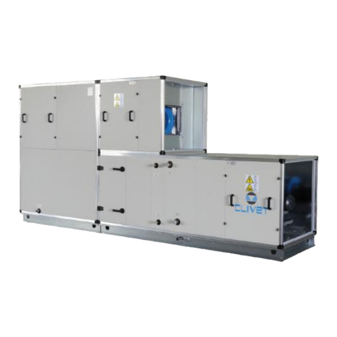
CLIVET CSRN-XHE2 Series User manual

CSRN-XHE2
49.4-110.4
R-410A
M07V40B13‐0711/20
MANUAL
FORINSTALLATION,
USEANDMAINTENANCE

2
The data contained in this manual is not binding and may be changed by the manufacturer without prior
notice. Reproduction, even partial, is FORBIDDEN. © Clivet S.p.A. - Feltre (BL) - Italia
Dear Customer,
We congratulate you on choosing these product
Clivet has been working for years to oer systems able to assure the maximum comfort for
a long time with highly-reliable, ecient, high-quality and safe solutions.
The target of the company is to oer advanced systems, that assure the best comfort and
reduce energy consumption as well as the installation and maintenance costs for the entire
life-cycle of the system.
With this manual, we want to give you information that are useful for all phases: from
reception, installation and use to disposal - so that such an advanced system can provide
the best performances during installation and use.
Best regards and have a good read.
CLIVET Spa

3
INDEX
Safety considerations 5
Configurations 7
Reception 10
Selecting the installation site 12
Water connections 17
Aeraulic connections 20
Electrical connections 21
Start-up 28
Control 36
Maintenance 60
Decommissioning 67
Residual risks 68
Technical information 70

4
SAFETY CONSIDERATIONS
Manual
The manual provides correct unit installation, use and
maintenance.
It is advisable to read it carefully so you will save time during
operations.
Follow the written indications so you will not cause damages to
things and injuries people.
Preliminaries
Only qualified personnel can operate on the unit, as required by
the regulation in force.
Risk situations
The unit has been designed and created to prevent injures to
people.
During designing it is not possible to plane and operate on all
risk situation.
Read carefully “Residual risk” section where all situation which
may cause damages to things and injuries to people are
reported.
Installation, starting, maintenance and repair required specific
knowledge; if they are carried out by inexperienced personnel,
they may cause damages to things and injuries people.
Intended use
Use the unit only:
civil air-conditioning
keep to the limits foreseen in the technical schedule and in
this manual
The manufacturer accepts no responsibility if the equipment is
used for any purpose other than the intended use.
Installation
Outdoor installation
The positioning, hydraulic system, refrigerating, electrics and the
ducting of the air must be determined by the system designer in
accordance with local regulations in force.
Follow local safety regulations.
Verify that the electrical line characteristics are in compliance
with data quotes on the unit serial number label.
Maintenance
Plan periodic inspection and maintenance in order to avoid or
reduce repairing costs.
Turn the unit off before any operation.
Pay particular attention to:
warnings / prohibitions / danger
indicating particularly important
operations or information, operations
that cannot be done, which compromise
the functionality of the unit or which
may cause damage to things or
persons.

5
Modification
All unit modifications will end the warranty coverage and the
manufacturer responsibility.
Breakdown/Malfunction
Disable the unit immediately in case of breakdown or malfunction.
Contact a certified service agent.
Use original spares parts only.
Using the unit in case of breakdown or malfunction:
voids the warranty
it may compromise the safety of the unit
it may increase time and repair costs
User training
The installer has to train the user on:
start-up/shutdown
set points change
standby mode
maintenance
what to do / what not to do in case of breakdown.
Data update
Continual product improvements may imply manual data changes.
Visit manufacturer web site for updated data.
Indications for the User
Keep this manual with the wiring diagram in an accessible place
for the operator.
Note the unit data label so you can provide them to the
assistance centre in case of intervention (see “Unit identification”
section).
Provide a unit notebook that allows any interventions carried out
on the unit to be noted and tracked making it easier to suitably
note the various interventions and aids the search for any
breakdowns.
In case of breakdown or malfunction
Immediately deactivate the unit
Contact a service centre authorized by the manufacturer
The installer must train the user, particularly on:
Start-up/shutdown
Set points change
Standby mode
Maintenance
What to do / what not to do in case of breakdown

6
Unit identification
The serial number label is positioned on the unit and allows to
indentify all the unit features.
The matriculation plate shows the indications foreseen by the
standards, in particular:
unit type
serial number (12 characters)
year of manufacture
wiring diagram number
electrical data
type of refrigerant
refrigerant charge
manufacturer logo and address
The matriculation plate must never be removed.
It contains fluorinated greenhouse gases.
Serial number
It identifies uniquely each unit.
Must be quoted when ordering spare parts.
Refrigerant
It contains fluorinated greenhouse gases
Type of refrigerant: R410A
Assistance request
Note data from the serial number label and write them in the
chart on side, so you will find them easily when needed.
Series
Size
Serial number
Year of manufacture
Number of electrical wiring diagram

7
R. Return air
S. Supply air
1. G4 efficiency filters + electronic filters (option)
or F7 filter (option)
2. Handling exchanger
3. Supply fan section
4. Hot gas reheating exchanger
5. Electric heaters.
6. Thermodynamic recovery on exhaust air
R. Return air
S. Supply air
FA. Fresh air
1. G4 efficiency filters + electronic filters (option)
or F7 filter (option)
2. Handling exchanger
3. Supply fan section
4. Hot gas reheating exchanger
5. Electric heaters.
6. Thermodynamic recovery on exhaust air
123
546
R
S
123
546
R
S
FA
123
546
R
S
CONFIGURATIONS
CAK configuration
Single fan section for full recirculation
CBK configuration
Single fan section for recirculation and fresh air

8
CCK configuration
Double fan section for recirculation, fresh air, exhaust, thermodynamic recovery
CCKP configuration
Double fan section with fresh air and THOR thermodynamic recovery
R. Return air
S. Supply air
FA. Fresh air
EX. Exhaust air
1. G4 efficiency filters + electronic filters (option)
or F7 filter (option)
2. Handling exchanger
3. Supply fan section
4. Hot gas reheating exchanger
5. Electric heaters.
6. Thermodynamic recovery on exhaust air
7. Exhaust damper
8. Exhaust fan section
9. Thermodynamic recovery on exhaust air
10. Thermodynamic recovery exchanger, THOR
123
546
R
S
FA
987
EX
123
546
R
S
FA
987
EX
10

9
Supply and return configuration
1° filtering stage - standard G4 ISO 16890 Coarse 60%
2° filtering stage - option F7 ISO 16890 ePM1 55%
2° filtering stage - option FES (electronic filters) ISO 16890 ePM1 90%
Filters nomenclature according to EN ISO 16890
Standard unit Option Option
Option Option Option

10
RECEPTION
Saftey
Operate in compliance with safety regulations in force.
For detailed information (dimensions, weight, technical
characteristics etc.) please refer to the TECHNICAL INFORMATION
section.
Use single protection devices: gloves, glasses etc.
Reception
You have to check before accepting the delivery:
That the unit hasn’t been damaged during transport
That the materials delivered correspond with that indicated on
the transport document comparing the data with the
identification label positioned on the packaging.
In case of damage or anomaly:
write down on the transport document the damage you found
and quote this sentence: “Conditional acceptance clear
evidence of deficiencies/damages during transport”
wontact by fax and registered mail with advice of receipt to
supplier and the carrier.
NOTE
Any disputes must be made within 8 days from the date of
the delivery. Complaints after this period are invalid .
Storage
Respect the indications on the outside of the pack.
In particolar:
minimum ambient temperature –15°C
(possible components damages)
maximum ambient temperature +49°C
(possible safety valve opening)
maximum relative humidity 95%
(possible damages to electrical components
NOTE
The unit may not be tilted more than 15° during transport.
NOTE
Removal of packaging
Be careful not to damage the unit.
Recycle and dispose of the packaging material in compliance with
local regulations.

11
A
B
Handling
Caution
Check that all handling equipment complies with local safety
regulations (cran, forklifts, ropes, hooks, etc.).
Provide personnel with personal protective equipment suitable
for the situation, such as helmet, gloves, accident-prevention
shoes, etc.
Observe all safety procedures in order to guarantee the
safety of the personnel present and the of material.
Verify unit weight and handling equipment lifting capacity.
Identify critical points during handling (disconnected routes,
flights, steps, doors).
Suitably protect the unit to prevent damage.
Lifting with balance (A)
Lifting with spacer bar (B)
Align the barycenter to the lifting point
Gradually bring the lifting belts under tension, making sure
they are positioned correctly.
Before starting the handling, make sure that the unit is
stable.

12
SELECTING THE INSTALLATION SITE
Positioning
Installation must be in accordance with local regulations. If
they do not exist, follow EN378
.
During positioning consider these elements:
customer approval
unit weight and bearing point capacity
safe accessible position
functional spaces
spaces for the air intake/exhaust
electrical connections
max. distance allowed by the electrical connections
water connections
Functional spaces
Functional spaces are designed to:
guarantee good unit operation
carry out maintenance operations
protect authorized operators and exposed people
Respect all functional spaces indicated in the TECHNICAL
INFORMATION section.
Positioning
Units are designed to be installed:
EXTERNAL
in fixed positions
Put the unit in a position where any leaking gas cannot enter
buildings or stagnate in closed areas. In the latter case,
observe the rules for machinery rooms (ventilation, leak
detection, etc.).
Installation standards:
install the unit raised from the ground
bearing points aligned and leveled
discharged condensation water must not cause harm/danger
to people and property
the accumulation of snow must not cause clogging of the
coils
avoid installations in places subject to flooding
Limit vibration transmission:
use anti-vibration devices or neoprene strips on the unit
support points
install flexible joints on the hydraulic and aeraulic connections
Protect the unit with suitable fence in order to avoid access to
unauthorised personnel (children, vandals, etc.)
A correct circulation of the air is mandatory to guarantee the
good unit operating..
The unit must be level.
Steel structure
Concrete floor
1 2 cm thick neoprene strips
2 concrete floor
3 floor
1 anti-vibration devices
2 steel structure
3 steel structure

13
Avoid therefore:
obstacles to the airflow
exchange difficulties
leaves or other foreign bodies that can obstruct the exchange
batteries
winds that hinder or favour the airflow
heat or pollution sources close to the unit (chimneys,
extractors etc)
stratification (cold air that stagnates at the bottom)
recirculation (expelled air that is sucked in again)
positioning below the level of the threshold, close to very high
walls, attics or in angles that could give rise to stratification
or recirculation phenomenons.
Ignoring the previous indications could:
energy efficiency decrease
alarm lockout due to HIGH PRESSURE (in summer) or LOW
PRESSURE (in winter)
CBK, CCK, CCKP configurations only
Avoid the accumulations of snow and ice in front of the exhaust
air outlet.
Pressure relief valve gas side
The installer is responsible for evaluating the opportunity of
installing drain pipes in compliance with the local regulations in
force (EN 378).
If ducted, the valves must be sized according to EN13136 .
Only if electronic filter is present
The most common contaminants for which the filter is designed,
are:
air pollution by PM10, PM 2,5 and PM1
Contaminants that can be filtered:
dry smokes
powder (up to 0,3 microns)
smoke electrostatically charged
Contaminants that can NOT be filtered:
water vapors also in low concentration
oil vapors
large amounts of dust
metal shavings,iron filing dusts and waste generally
Gas
Absolutely to avoid:
metal dusts also fine
fumes produced by combustion of organic and not materials
(wood, coal, gasoline, etc.)
only CBK, CCK, CCKP
Avoid snow accumulating

14
Gas heating module
Option
Burner with low pollutant emissions (NOx below 80 mg/kWh), in line with Class 5 of the EN 676 European
standard is supplied with a gas increase control for methane or LPG.
The heating module with burner includes:
hot air generator powered with methane
kit for transformation of power with liquefied petroleum gas (LPG)
kit of steel chimney for exhaust fumes
all the control and safety devices
The component requires gas supply (gas connections to be made by the Customer).
The location of the unit and the fume drain mode must comply with laws and standards in force in the
Country of use.
The Costumer may choose the flue chimney.
The Costumer is responsible for mounting the chimney kit during installation.
Based on the specific installation requirements, the length of the chimney can be increased with suitable
joints and fittings (not supplied by Clivet).
Gas connection
Read the gas heating module manual.
Connection must be carried out by qualified personnel.
use certified components and comply with the local standards in force
install on the gas connection: tap, large section filter and anti-vibration joint
check the supply pressure is correct and stable, in particular where more uses are inserted on the same
line.
System maintenance booklet
t must be kept in the place of installation of the unit
It must be filled-in upon commissioning
It must be updated with the results of the periodical checks, of the routine and extraordinary
maintenance interventions.
Gas cock
Gas filter (large section)
Anti-vibration joint
Gas filter (small section)
Safet gas solenoid vlave
Pressure stabiliser
Main gas burner solenoid valve
Pilot burner gas solenoid valve

15
1 remove the unit supply flange closing.
2 approach the unit to the Gas Module.
3 match the supply flanges by means of the supplied terminals.
4 tighten screws
5 guarantee the absence of air bypass.
A. Apply the flat adhesive gasket15x5 on the Gas Module flange perimeter to guarantee the absence
of air bypass.
B. Fix with screws the flue supporting bracket to the GM frontal panel
C. Fix the extensions with clamps to the flue supporting bracket
D. Fix the suction terminals in ambient and the fuel components (curves, extensions, terminals) by the
corresponding gaskets

16
Gas use features
Connections performed by costumer
A. rooftop
B. supply fan
C. gas module
D. connecting cables
E. electrical panel - terminal XG

17
P
H
S
T
A
WATER CONNECTIONS
Condensate drain
The condensate must be disposed in order to avoid damages to
people and things.
Unit discharge fitting: the connection must not transmit
mechanical stresses and must be performed taking care not to
damage the unit discharge fitting.
Provide a siphon that, eliminating the negative pressure caused
by the fan, prevents the air intake from the discharge duct.
The connection between the attachment and the siphon must
be hermetically sealed (A)
The piping must have adequate slope to allow out flow.
Anchor the ducting with an adequate number of supports..
Otherwise are generated duct failures and air locks that
prevent the runoff.
Insulate the duct and the siphon to avoid the condensate
drippings.
Connect the condensate discharge to a sewerage drainage
network.
DO NOT use white water or drainage networks to avoid the
aspiration of odours in the case of evaporation of water
contained in the siphon.
Check at the end of the work, the regular condensate runoff
pouring some water in the tray.
Siphon height calculation
T = 2P
S = T/2
P is the pressure determined by the fan in correspondence of the
condense collection bowl (approx. 1 mm = 9.81 Pa)
Example :
P = 300 Pa = 30 mm
T = 2P = 60 mm
S = T/2 = 30 mm
Condensation in winter operation
When a heat pump is running it produces a considerable amount
of water due to the defrosting cycles of the external coil.
The condensate must be disposed in order to avoid damages to
people and things.
Risk of freezing
Prevent the risk of freeze if the unit, drain or plumbing
connections can be subject to temperatures close to 0°C.
isolate the piping
protect the piping with heating cables laid underneath the
insulation

18
Immersed electrode humidifier
Option
Connexion humidificateur: 1” F
Supply water
The humidifier must be supplied with mains water having the following features:
pressure between 0.1 and 0.8 Mpa (1 – 8 bar)
temperature between 1 and 40°C
Do not use:
water treated with softeners: it can corrode the electrodes and form foam with possible faults/
malfunctionings
pit, industrial or potentially polluted (chemically or bacteriologically) water
disinfectants or anti-corrosive substances mixed with water, as potentially irritating
Supplying the humidifier with water treated with reverse osmosis filtering system gives the following
advantages:
reduces limescale deposits
reduces energy consumptions
reduces maintenance costs
increases humidifier duration
Check that the filter guarantees a water flow rate higher than the flow rate of the installed humidifier.
Limit values for the supply water
Respect the limits indicated in the table
No relation can be demonstrated between water hardness and conductivity.
Limit values for the supply
water
conductivity medium-low medium-high
min max min max
Hydrogen ions pH 7 8,5 7 8,5
Specific conductivity at 20°C μS/cm 125 500 300 1250
Total dissolved solids TDS mg/l (1) (1)(1) (1)
Dry residue at 180°C R 180 mg/l (1) (1)(1) (1)
Total hardness TH mg/l CaCO350
(2) 250 100
(2) 400
Temporary hardness mg/l CaCO330
(3) 150 60
(3) 300
Iron + Manganese mg/l Fe+Mn 0 0,2 0 0,2
Chloridesppm Cl 0 20 0 30
Silica mg/l SIO20 20 0 20
Residual chlorine mg/l Cl-0 0,2 0 0,2
Calcium sulphate mg/l CaSO40 60 0 100
Metallic impurities mg/l 0 0 0 0
Solvents, diluents, soaps,
lubricants
mg/l 0 0 0 0
(2) not lower than 200% of the chloride
content in mg/l of Cl-
(3) not lower than 300% of the chloride
content in mg/l of Cl-
(1) Values depending on specific conductivity;
in general:
Drainage water
It can reach a temperature of 100°C.
It contains the same substances of the supply water but in higher concentration.
As it is not toxic, it can be disposed of with white waters.

19
Heating coil
Option
Max. operating pressure = 10 bar
A drain cock
B vent valve
Provided by the costumer:
1 anti-vibration devices
2 piping supports
3 Shut-off valves
13
A
B
2

20
AERAULIC CONNECTIONS
The dimensioning and correct execution of the aeraulic
connections are fundamental to guarantee good unit operation
and adequate level of silence in the room.
When designing and manufacturing the ducting, consider LOAD
LOSSES, AIR FLOW AND SPEED that must be consistent with the
unit features.
Particularly consider that load losses higher than the unit useful
prevalence, lead to reduction in flow rate, with consequent unit
blocks.
the weight of the channels must not burden on the connection
flanges
place anti-vibration joints between channels and unit
connection to the flanges and between the various sections of
the channels must guarantee air seal, avoiding dispersions
penalising the overall efficiency of the system
limit the load losses by optimising the path, the type and
number of bends and junctions
use wide bends evaluating the opportunity of equipping them
with deflectors (in particular with high air speed or bends with
reduced radius)
Treated air channelling
The internal surface of the channel must be smooth, enable its
washing and must not contaminate the air.
Thermally isolate the channels and the flanges to avoid energy
losses and forming of condensation.
DIFFUSERS INLETS GRILLES
A correct diffusion of the air in the room is determining for the
level of comfort.
When choosing and positioning the grilles, inlets and diffusers,
avoid:
excessive air speed
forming of stagnant and stratification areas
cold air delivery in room
forming of localised currents (also due to uneven distribution
of air)
excessive room temperature variations, vertically and
horizontally
short circuits of the supply air towards the return air
For sound comfort, consider that:
the air diffusers must be chosen verifying the sound power
generated at nominal flow rate conditions
the cut-off to diffusers must be carried out with flexible
elements
the return grilles must be widely dimensioned
Isolate the channels
Isolate the flanges
Other manuals for CSRN-XHE2 Series
1
Table of contents
Other CLIVET Air Handler manuals
Popular Air Handler manuals by other brands

Juwent
Juwent OptiMax-10 Original instruction manual

Gree
Gree U-match Series Service manual
BLAUBERG Ventilatoren
BLAUBERG Ventilatoren Freshbox 100 WiFi user manual
Euroclima
Euroclima ZHK NANO instruction manual
Trox Technik
Trox Technik PURELINE18 installation manual
Mars
Mars TGRX Series Installation and maintenance instructions
